Reinforcement Detailing of Beams from ETABS output
Aim/Objective:
i) "The objective is to intricately design the beams using ETABS 2018."
ii) "Additionally, we aim to furnish specific information regarding the longitudinal and shear reinforcement for two connected beams."
iii) "Furthermore, we will determine the maximum shear force within one of the spans in the continuous beams."
iv) "Moreover, we will investigate and elucidate the causes behind the middle span failure along grid A."
Introduction:
1) "Beams serve as horizontal structural elements responsible for bearing lateral loads."
2) "In conventional reinforced concrete structures, beams primarily bear loads from the floor slab. However, they may also experience additional loads like those from walls, finishes, and service installations."
3) "The process of designing and detailing RC beams encompasses selecting the appropriate beam dimensions and determining the necessary amounts of longitudinal and shear reinforcement to meet both ultimate and serviceability limit state criteria."
4) "Subsequently, it is crucial to ensure that the placement and arrangement of beam reinforcements on the construction site are done accurately, in order to prevent any construction errors."
Procedure:
The steps for the procedure are outlined below in a sequential format.
i. Step 1:
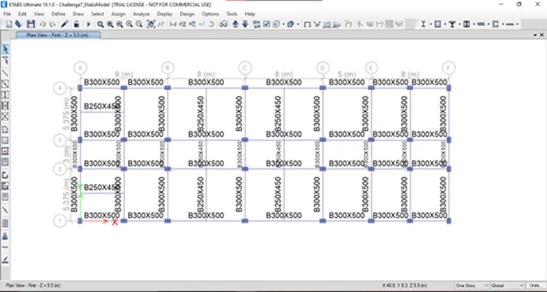
1) Begin by accessing the provided Challenge 7 attachment and proceed to download it.
2) Once the download is complete, open the Challenge in the ETABS software.
ii. Step 2:
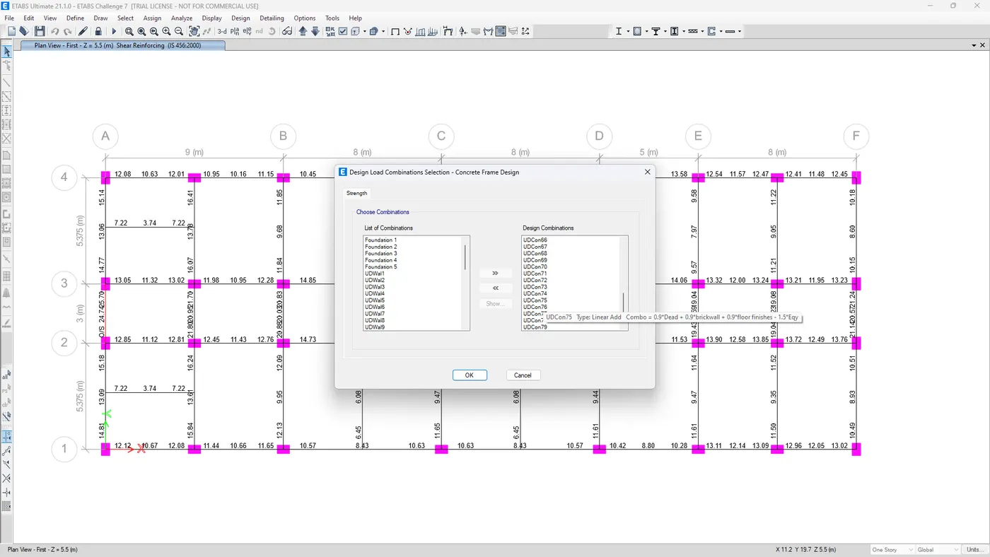
3) Next, verify the existing load combinations already established in the provided modeling file.
iii. step 3:
4) cheking the model and analysing it.
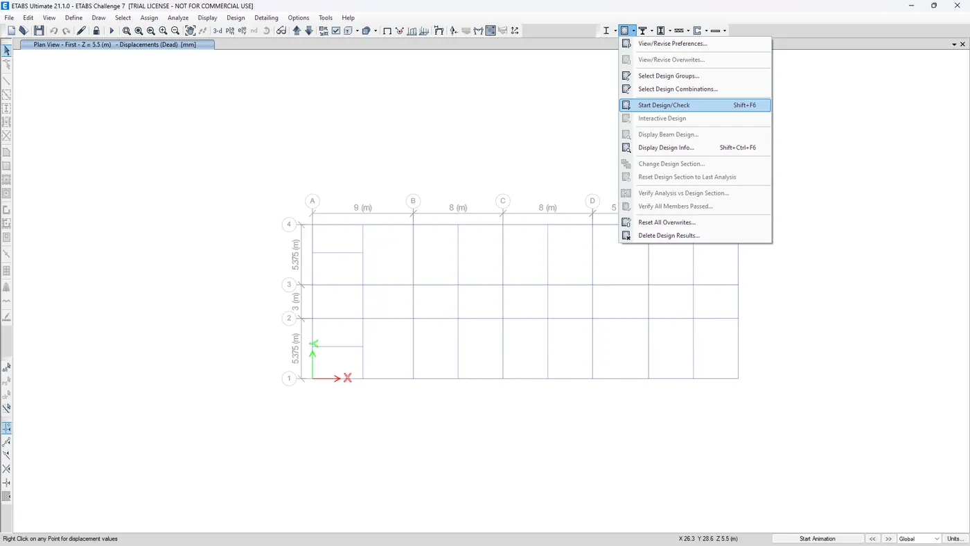
5) Proceed by initiating the beam design process through the selection of the 'Start Design/Check' option.
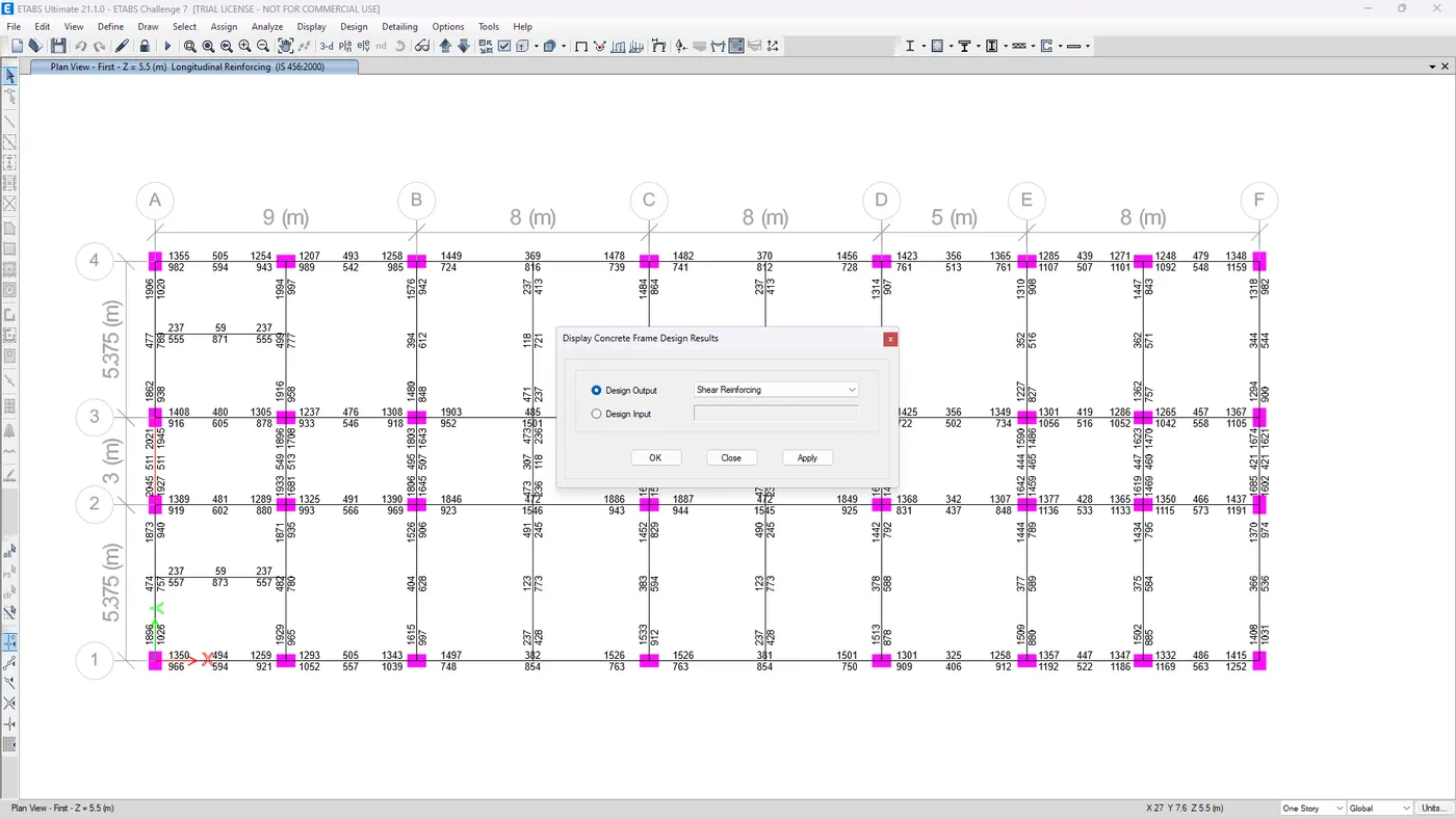
6) Upon clicking on "Start/Design Check," a window will appear displaying the concrete frame design results.
7) Within this window, you have the option to select the specific design output you desire.
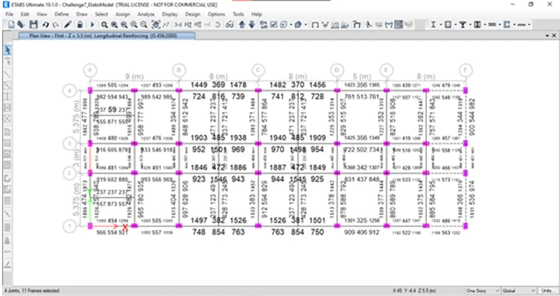
8) To proceed, select "Longitudinal Reinforcement.
iv. Step 4:
9) When you click on it, the details of longitudinal reinforcement will be displayed.
Step 5:
i) Reinforcement details along Grid A:
- Max Ast at bottom support = 1945 mm2
- Max Ast at bottom middle = 789 mm2
- Max Ast at Top support = 2046 mm2
- Max Ast at Top middle = 511 mm2
Reinforcement Calculation: - For Top:
- Total Ast required at top is = 2046
- So we can provide 4 bars of diameter 20 mm and 4 bars of 16 mm satisfies the overall Ast
4 x T20 = 1256 mm2
4 x T16 = 804 mm2
4 X T20 + 4 x T16 = 2060 mm2
Hence Satisfy.
ii) For Bottom :
- i) Total Ast required at top is = 1945
So we can provide - 3 bars of diameter 20 mm and 5 bars of 16 mm satisfies the overall Ast
3 x T20 = 942 mm2
4 x T16 = 1004 mm2
3 X T20 + 5 x T16 = 1946 mm2 Hence Satisfy.
iii) For Shear details:
10) Right-click and choose "View Details.
11) Proceed to select "Shear Details.
12) According to Clause 6.3.3, the spacing up to 2 times the depth from the face of the column should be 100 units.
13) This spacing should not exceed this specified value.
14) Therefore, furnish three-legged stirrups with a diameter of 10mm and a 100mm spacing throughout the length of the beam.
Step 6:
i) Reinforcement details along Grid 3 :
- Max Ast at bottom support = 1042 mm2
- Max Ast at bottom middle = 1501 mm2
- Max Ast at Top support = 1940 mm2
- Max Ast at Top middle = 485 mm2
Reinforcement Calculation :- 1) For Top -
i) Total Ast required at top is = 1940 mm2��2
So we can provide
3 bars of diameter 20 mm and 5 bars of 16 mm satisfies the overall Ast
3 x T20 = 942 mm2
4 x T16 = 1004 mm2
4 X T20 + 4 x T16 = 1946 mm2 Hence Satisfy
ii) For Bottom :
- Total Ast required at top is = 1501 mm2
So we can provide - 3 bars of diameter 20 mm and 3 bars of 16 mm satisfies the overall Ast
3 x T20 = 942 mm2
3 x T16 = 603 mm
3 X T20 + 5 x T16 = 1545 mm2 Hence Satisfy .
iii) For Shear details :
15) Right Click on and Click on Details
16) Click on Shear Details
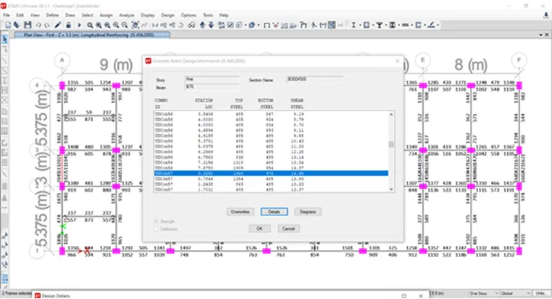
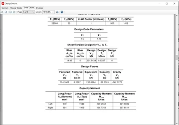
17) In accordance with Clause 6.3.3, it is required to maintain a spacing of 100 units up to 2 times the depth from the face of the column.
18) This spacing should not exceed the specified limit.
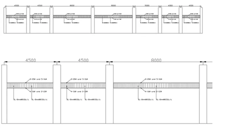
19) Thus, furnish three-legged stirrups with a diameter of 8mm, maintaining a 100mm spacing along the entire length of the beam on both sides.
20) Additionally, incorporate three-legged stirrups with an 8mm diameter, positioned at mid-span, with a spacing of 150mm.
Step 7:
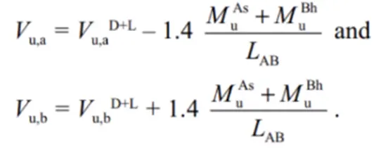
21) Next, we proceed to conduct a check for Sway shear.
- A) Specifically for the case of Right Sway,
We are aware that the formula to calculate...
-
From Etabs Model results substitute the value -
i) VD+Lu= 92 Kn
ii) Mas= 176 kn-m
iii) Mbℎ= 295 kn
iv) Lab = 4.725 m
Put this value in above eqn
we get ,Vu,a= 48 KnVu,b = 230 Kn
- B) For Left Sway
i) Follow the same process
ii) We know the formula 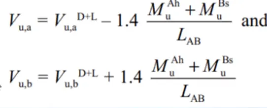
- From Etabs Model results substitute the value
ii) Maℎ= 236 kn
iii) Mbs= 150 kn
iv) Lab = 4.725 m
Put this value in above eqn
we get ,
V_(u,a)`= 190 Kn
Vu,b = 50 Kn
- C) Existing Shear capacity in beam as per Is 456-2002
i) We know the formula -
Put the values -
ii) Asv = 151 mm2
iii) Spacing = 100 mm
iv) d = 450 mm
we get
Vus) = 246 kn > 230 kn ( Shear sway)
Results:
i) The beam design has been successfully completed with detailed reinforcement.
ii) To address the failure of the middle span along Grid A, it is important to analyze the potential causes and explore potential solutions.
- The primary reason for the failure of the middle span along Grid A is that the shear stress has exceeded the prescribed limit.
- This could be attributed to the higher shear force acting on the beam, potentially compounded by insufficient shear reinforcement at the end supports.
- Potential Solutions:
(a) Introducing a higher grade of concrete specifically in that particular section.(b) Reducing the applied shear force in the section of the beam.
(c) Providing increased shear reinforcement capable of withstanding the shear force in that section.
iii) To calculate the value of the maximum shear force in any one of the spans in both continuous beams, we will apply the provisions outlined in Clause 6.3.3(b) of IS 13920 – 2016.
- Since we've already computed the shear force value in accordance with Clause 6.3.3(b) of IS 13920 - 2016...
- The shear sway values at both the right and left supports fall within acceptable limits.
- 246kn > 230kn and hence this is safe.