ANALYSIS And DESIGN Of RCC SHEAR WALLS USING ETABS
Aim/Objective:
The objective is to perform an analysis and design of the RCC shear walls for a six-story building using the provided ETABS file. This pertains specifically to the shear wall located at grid A-11 in the structural model, which has dimensions of 300x1500. Please ensure that the ETABS model displays the designated shear wall.
Introduction:
Shear walls resist lateral forces and are vital for seismic resistance in concrete structures. They provide significant stiffness, reducing inter-story distortions during earthquakes. The chapter covers shear wall analysis with moment-resisting frames. Coupled shear walls, with multiple walls connected by beams or slabs, exhibit enhanced stiffness. Openings are common, connected by beams, forming coupled shear walls. The analysis using Rosman’s continuous medium method is also discussed.
Procedure:
Step 1:
1. Begin by downloading the provided previous Revit model file.
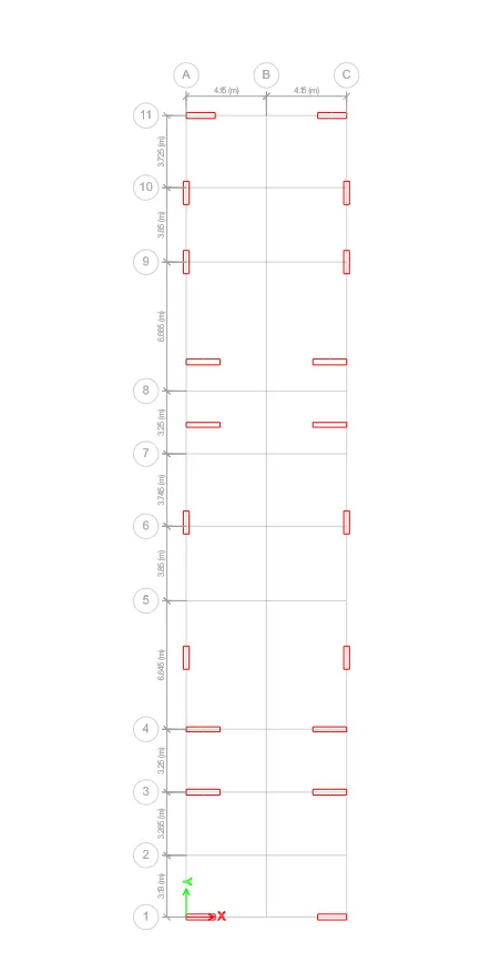
2. Open the Revit file and access the floor diagram displayed below.
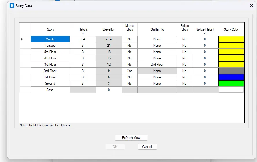
3. Place all stories in the bottom right corner.
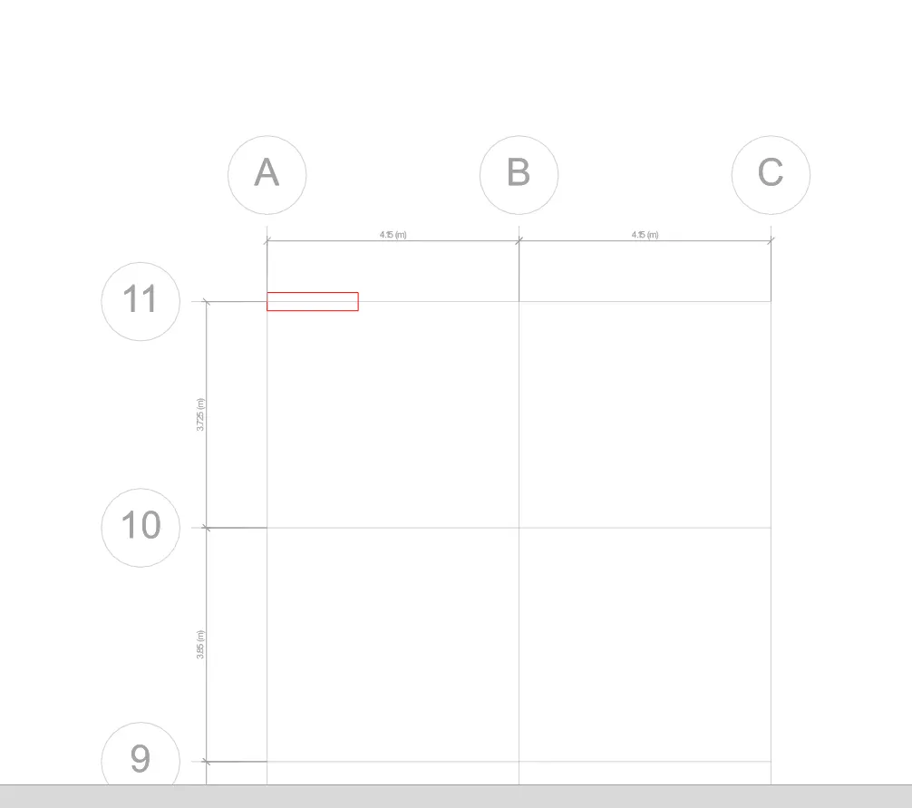
4. Next, choose the 11A wall, right-click, and select only the object indicated in the image below.
Step 2:
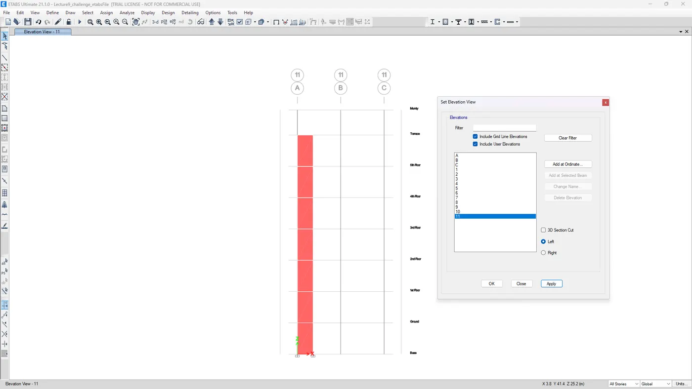
1. Navigate to the "Elevation" option in the top toolbar.
2. The elevation view dialogue box will appear.
3. Choose option 11 and click "Apply".
Step 3:
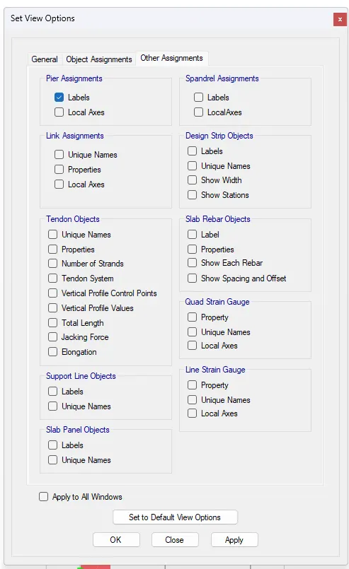
1. Click on the "Set Display" option.
2. The "Set View Option" dialogue box will open.
3. Select the label and click "Apply".
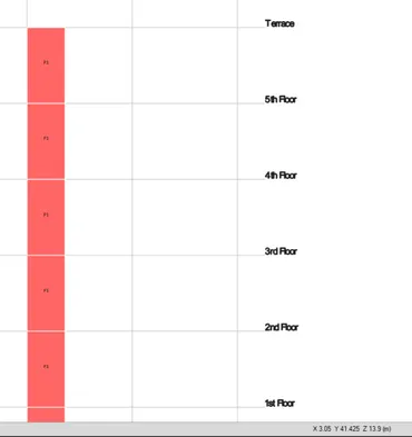
4. Verify if the label option is now visible, similar to 'P1'.
5. Return to the "Set Display" option, unselect the label, and click "Apply".
Step 4:
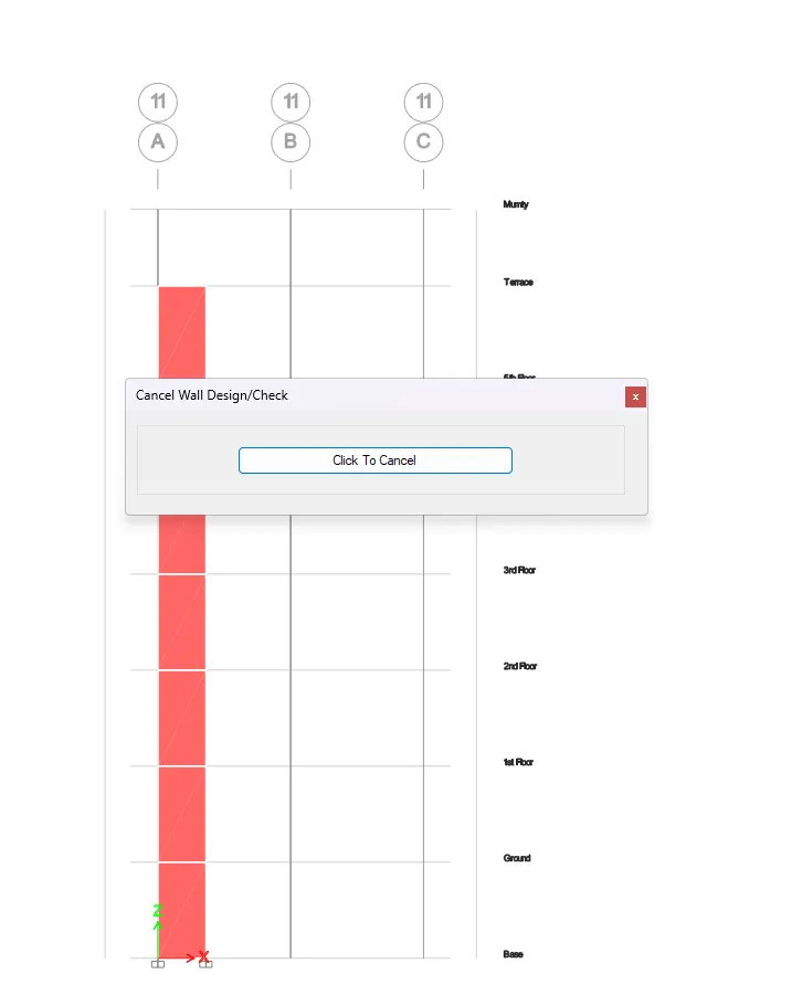
1. Analyze the model by utilizing the "Run Analysis" option.
2. Once the analysis is complete, select the "Shear Wall Design" option.
3. The model will undergo a design check.
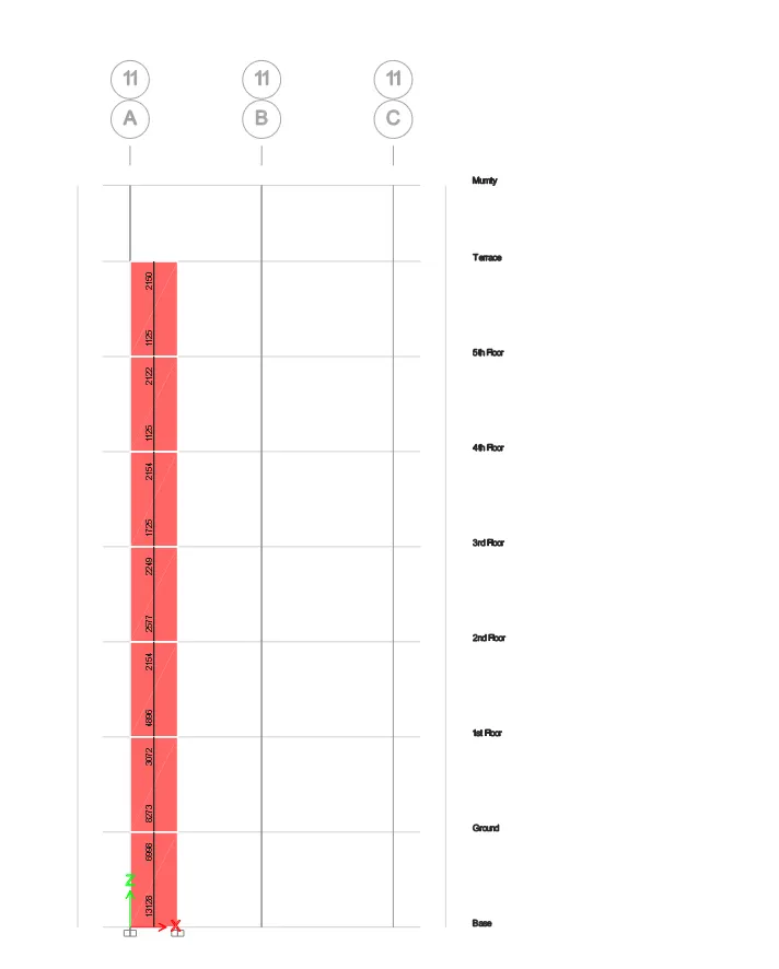
4. The shear wall values will be displayed.
Step 5:
1. Return to the "Shear Wall Design" option.
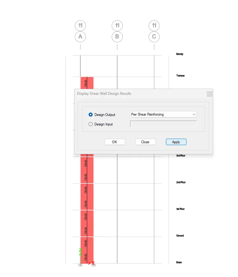
2. Select the "Display Design Info" option.
3. This will open a dialogue box displaying shear wall design results.
4. Choose the option for "Pier Shear Reinforcing".
Step 6:
1. Upon selecting "Pier Shear Reinforcing," the corresponding values will be displayed in the shear wall.
2. Next, proceed to select the "Pier Edge / Boundary Zone Walls," and their values will also be shown in the shear wall.
3. Navigate to the "Edit Grid Story" option and take a screenshot to draft the reinforcing details.
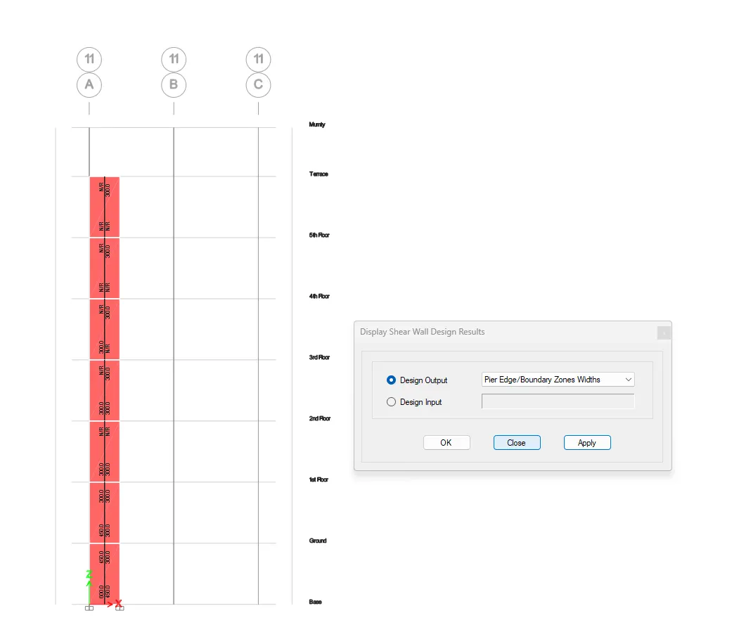
4. Right-click on the shear wall and select "Shear Wall Design Details" to review the specifics.
Step 7:
1. Utilizing AutoCAD software for creating the reinforcement detailing.
Step 8:
Calculation: Confirming with IS13920-2016
a) Overall height of the wall (h) = 21000mm, Length of the wall (L) = 1500mm
Ratio (h/L) = 21000/1500 = 14 > 2
The given RC wall is slender.
b) The largest diameter that can be used in the RC wall should not exceed 1/10th of the thickness of the wall.
So, 300/10 = 30mm. We used 25mm dia rebar in the detailing. Hence, OK.
c) The maximum spacing of longitudinal/transverse rebar should not exceed:
(i) 1/5th of horizontal length (1) = 1500/5 = 300mm
(ii) 3 times the thickness (t) = 3 x 300 = 900mm
(iii) 450mm
Therefore, we have to adopt a maximum 300mm spacing both for vertical and horizontal rebar inside the RC wall.
d) Minimum horizontal reinforcement calculation as per Table-1 of IS13920-2016:
(ph)min' > (Ph) min
= 0.0025 + 0.5
(hwLw-2)(ph-0.0025) > (hwLw - 2)(Pn - 0.0025)
= 0.01672 of the cross-section of the RC wall
= 1500 x 300 x 0.01672 = 7524 sq.mm for the entire RC wall height.
= 7524/21 = 358 sq.mm/meter height of the RC wall
We already provided 16mm dia at 100mm c/c spacing which will give = 1000/100 x 2 x 201 = 4020 sq.mm. Hence, OK.
e) Minimum boundary reinforcement calculation as per Table-1 of IS13920-2016:
(pv,be)min' > (Pv,bo) min
= 0.008
= 0.008 x 300 x 300 = 720 sq.mm
We already provided a minimum of 8 numbers of 12mm dia rebar = 8 x 113 = 904 sq.mm. Hence, OK.
f) Minimum web reinforcement calculation as per Table-1 of IS13920-2016:
(PV,web)min' > (Pv,web)min
= 0.0025
= 0.0025 x 900 x 300 = 675 sq.mm
We already provided a minimum of 8 numbers of 12mm dia rebar = 8 x 113 = 904 sq.mm. Hence, OK.
g) Minimum overall RC wall vertical reinforcement calculation as per Table-1 of IS13920-2016:
(PV,t)min' > (Pv, zt) min
= 0.0025 + 0.01375
(twLw)' > (twlw)
= 0.00525 times of wall cross-section
= 0.00525 x 1500 x 300 = 2363 sq.mm
We already provided a minimum of 24 numbers of 12mm dia rebar = 24 x 113 = 2712 sq.mm. Hence, OK.
h) Boundary element special confining reinforcement as per Clause 10.4.4 of IS13920-2016:
Ash = 0.05vh (Fckfy)" > Ash = 0.05Syh(Fakfy)
Maximum spacing of confinement is 100mm as per drawing.
h = minimum clear distance between longitudinal rebar = 150mm, say.
Ash > Ash = 45 sq.mm
We already provided two closed links of 16mm dia = 2 x 201 = 402 sq.mm. Hence, OK.
Result/Outcome:
The designated RC wall has been successfully designed and meticulously detailed using AutoCAD software. Furthermore, we have conducted a thorough verification of the clauses outlined in the ductility code, Indian standard IS13920-2016, pertaining to the detailing of the RC wall.
--THANK YOU--