Gate Valve Parametric Study
AIM: To perform a parametric study on Gate Valve.
PROCEDURE:
- First the model is imported to spaceclaim.
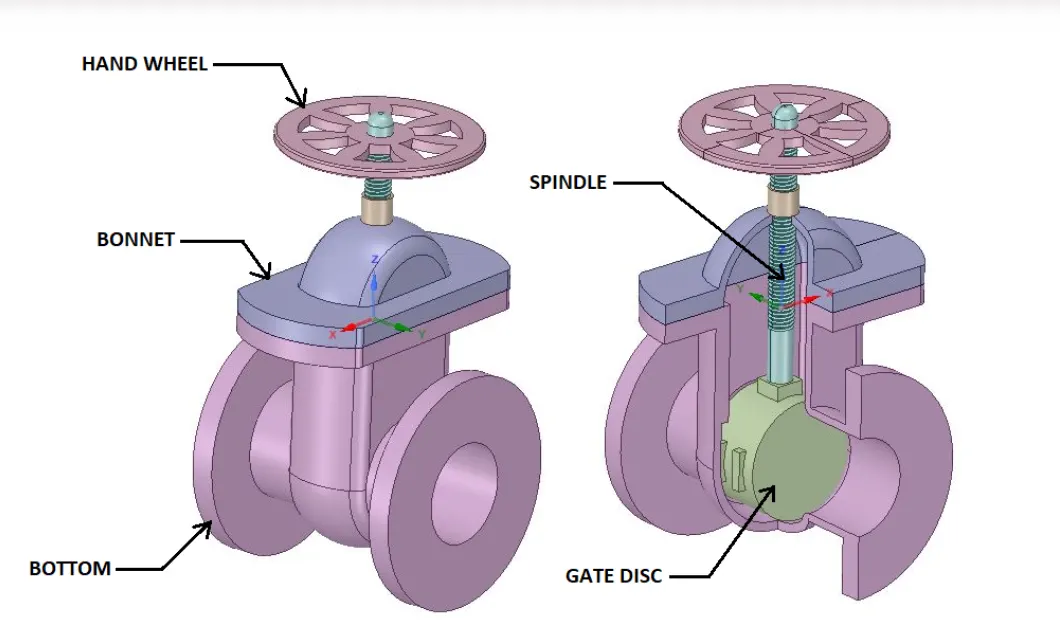
- Then the fluid volume is extracted using the extract tool.
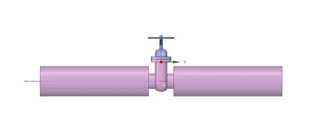
- After extracting the fluid volume the inlet and outlet are extended to 800mm.
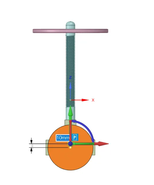
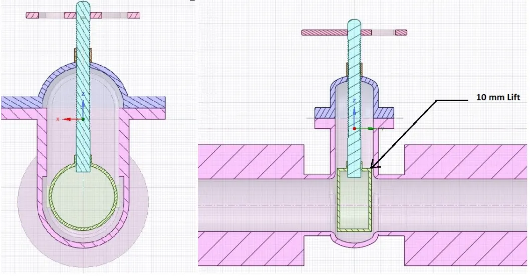
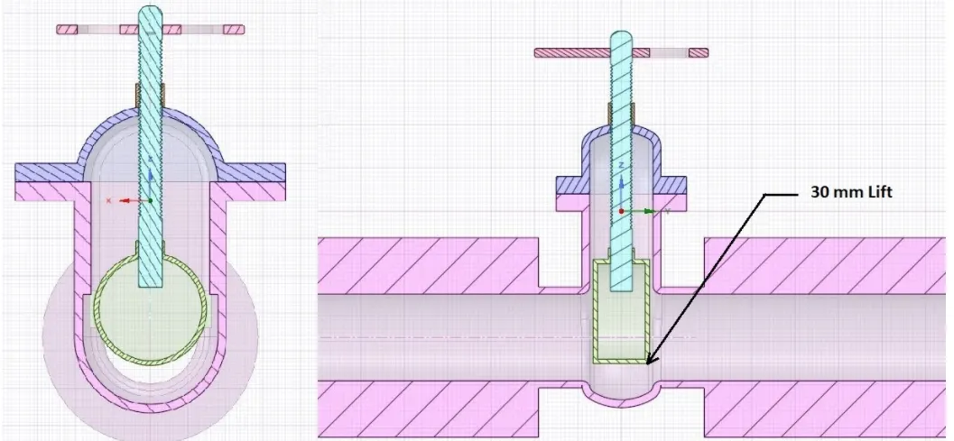
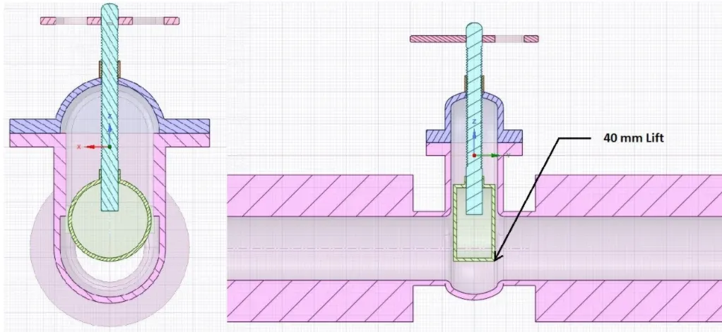
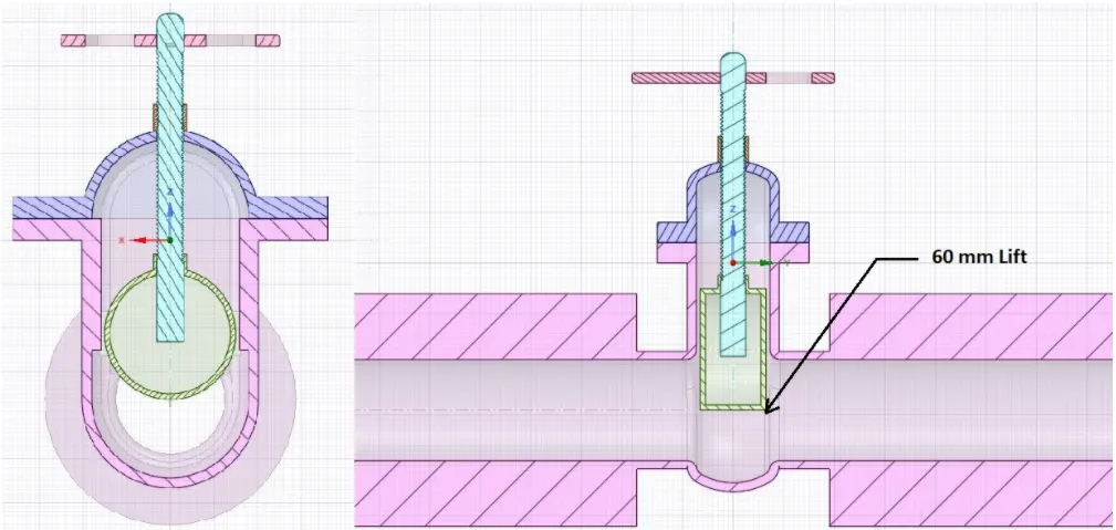
- Since the parametric study is based on the lift of the gate valve hence an initial lift of 10mm is given and then the value is parametrised.
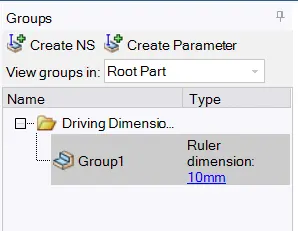
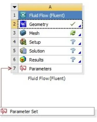
- After parametrisation, a group is created as well as a parameter tree is created.
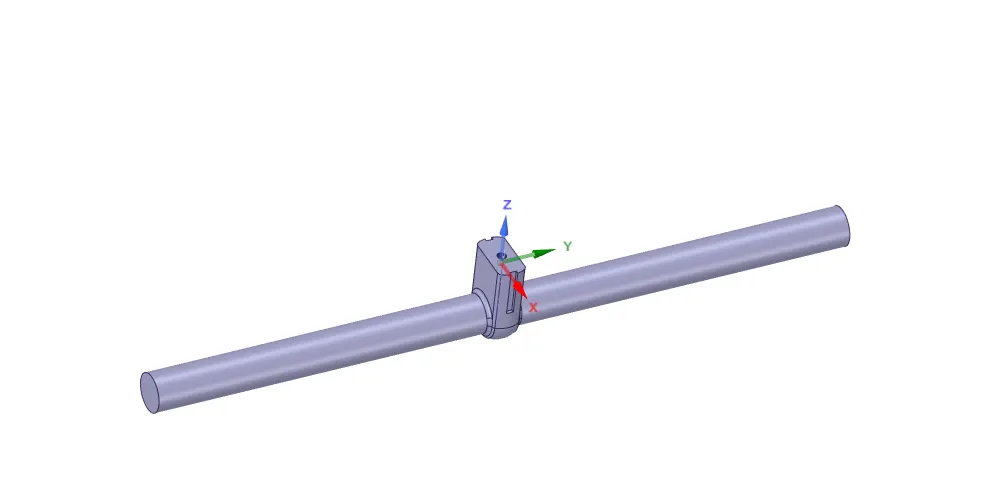
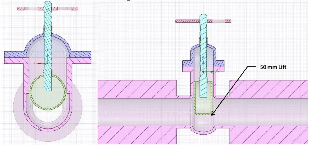
- Then the fluid volume is as follows:
Mesh:
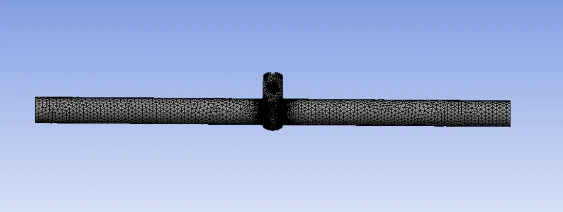
- Then the body is meshed and the inlet and outlet named selections are given.

Solving:
solver settings:
- analysis type -> steady state
- solver -> pressure based solver
- gravity -> -9.81 m/s2
- material -> water-liquid
- viscous model -> K-Epsilon realiazable
- near wall treatment -> scalable wall function
Boundary conditions:
- inlet -> Type: pressure inlet
gauge total pressure:10 Pa
- outlet -> Type: pressure inlet
gauge total pressure:0 Pa
Parametric study:
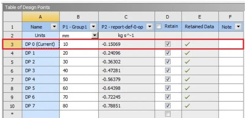
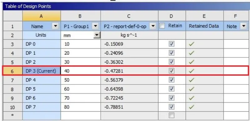
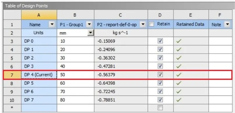
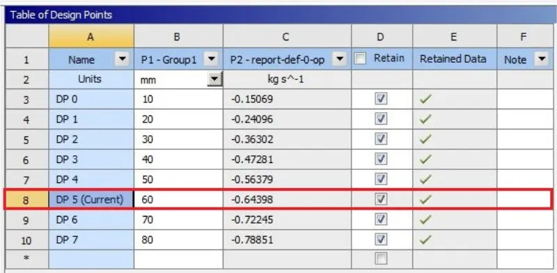
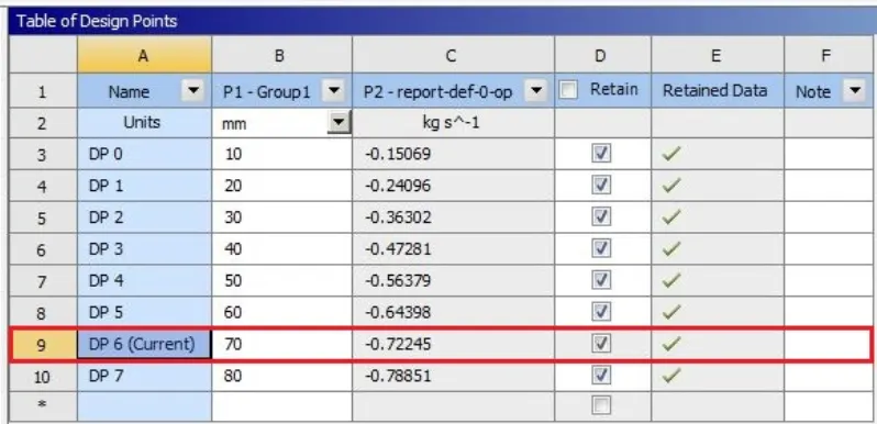
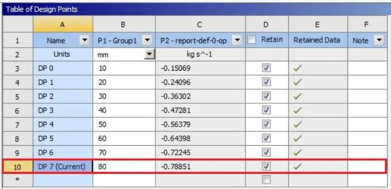
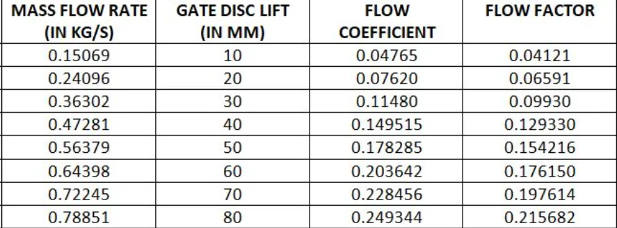
Now the parametric study is carried out for 10mm to 80mm lift values and their corresponding mass flow rate values are calculated.
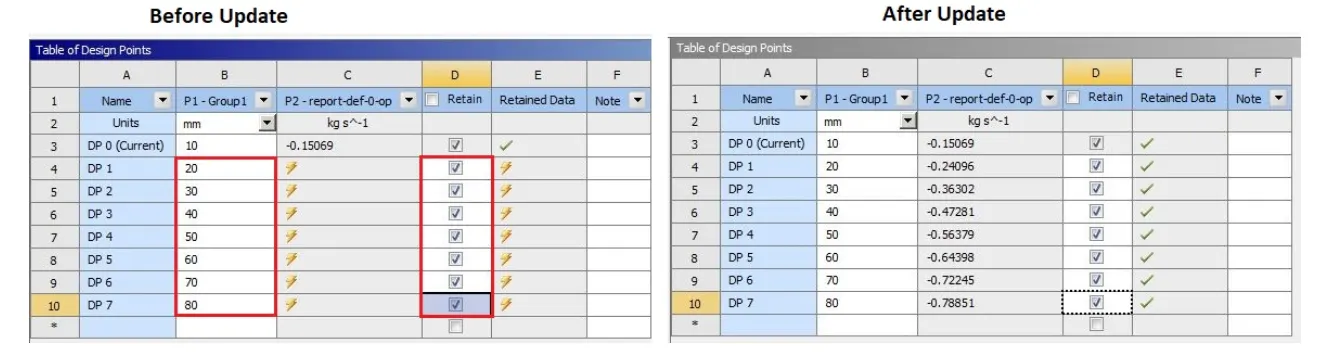
From the above table we see that as the lift increases, the mass flow rate also increases which is self explanatory.
Residuals:
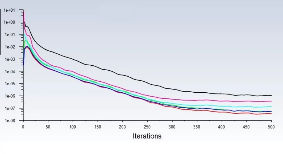
The simulation is carried out for 500 iterations and the solution is converged.
Results:
I. Flow coefficient:
The flow coefficient of a device is a relative measure of its efficiency at allowing fluid flow. It describes the relationship between the pressure drop across an orifice valve or other assembly and the corresponding flow rate.
Mathematically the flow coefficient Cv (or flow-capacity rating of valve) can be expressed as :
where:
- Q is the rate of flow (expressed in US gallons per minute),
- SG is the specific gravity of the fluid (for water = 1),
- ΔP is the pressure drop across the valve
II. Flow factor:
The metric equivalent flow factor is calculated using metric units :

where
- Kv is the flow factor
- Q is the flowrate
- SG is the specific gravity of the fluid (for water = 1),
- ∆P is the differential pressure across the device
Kv can be calculated from Cv using the equation:

Case-1: 10mm Lift
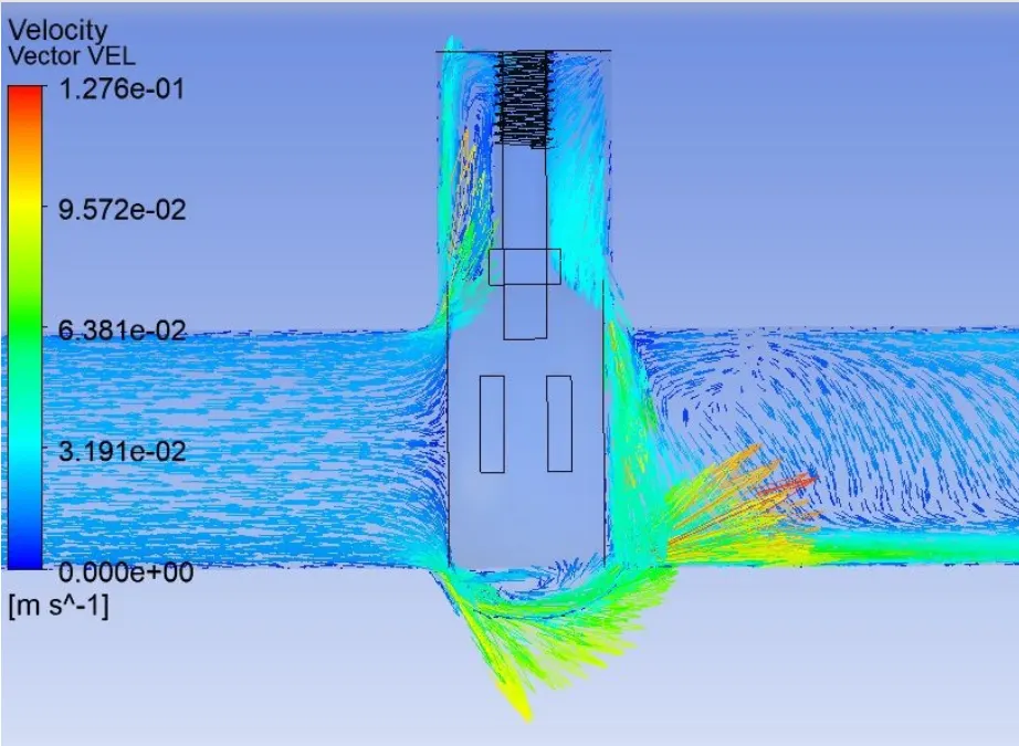
Velocity contour:
Flow coefficient and flow factor:

where Q = 0.15069
SG = 1
ΔP = 10
By substituing the above values we get `C_v` = 0.04765
`K_v` = 0.865*0.04765 = 0.04121
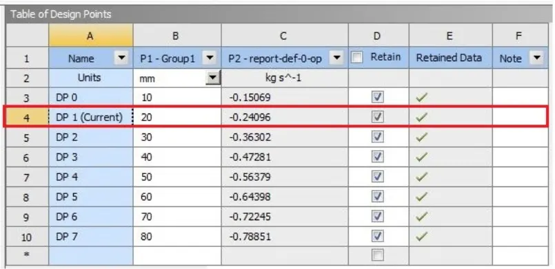
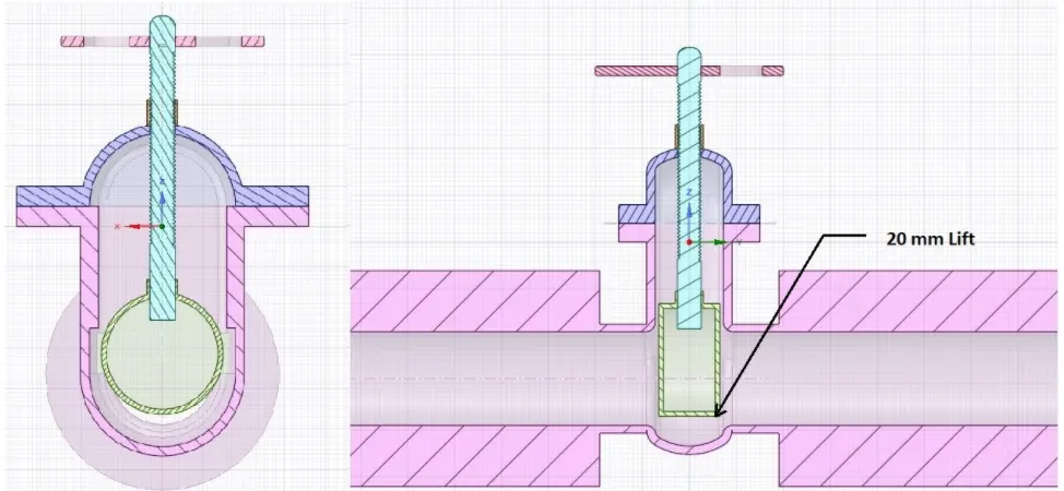
Case-2: 20mm Lift
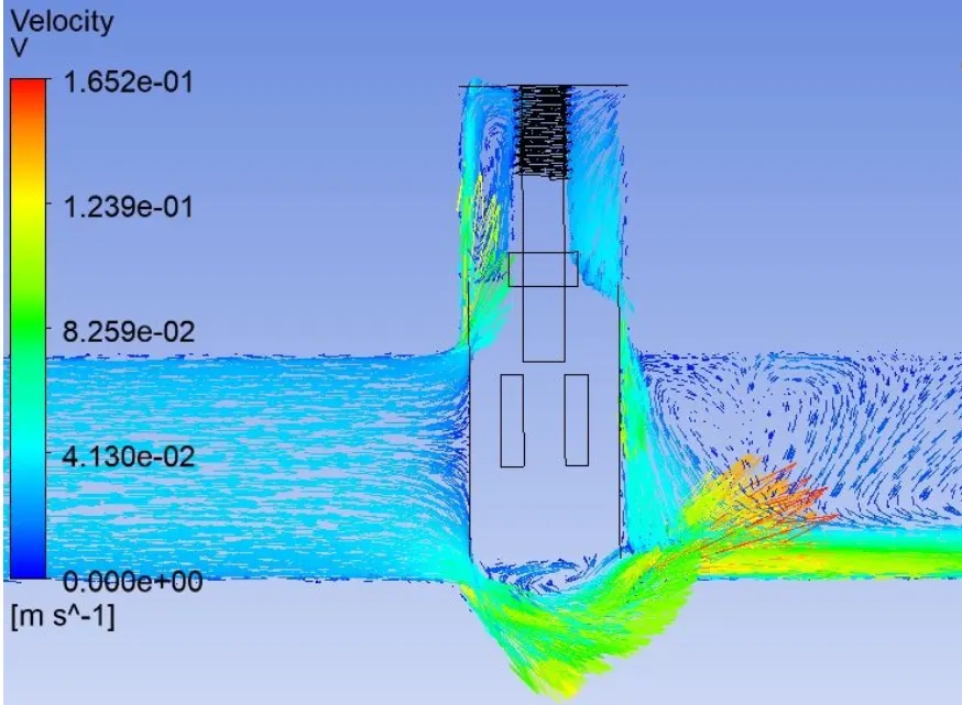
Velocity contour:
Flow coefficient and flow factor:
where Q = 0.24096
SG = 1
ΔP = 10
By substituing the above values we get `C_v` = 0.07620
`K_v` = 0.865*0.07620 = 0.06591
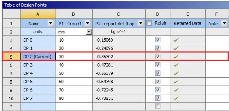
Case-3: 30mm Lift
Velocity contour:
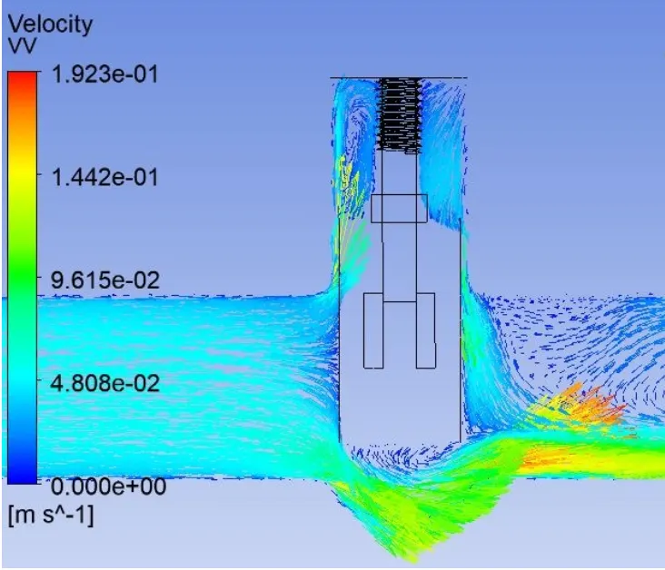
Flow coefficient and flow factor:
where Q = 0.36302
SG = 1
ΔP = 10
By substituing the above values we get `C_v` = 0.11480
`K_v` = 0.865*0.11480 = 0.09930
Case-4: 40mm Lift
Flow coefficient and flow factor:
where Q = 0.47281
SG = 1
ΔP = 10
By substituing the above values we get `C_v` = 0.149515
`K_v` = 0.865*0.149515 = 0.129330
Velocity contour:
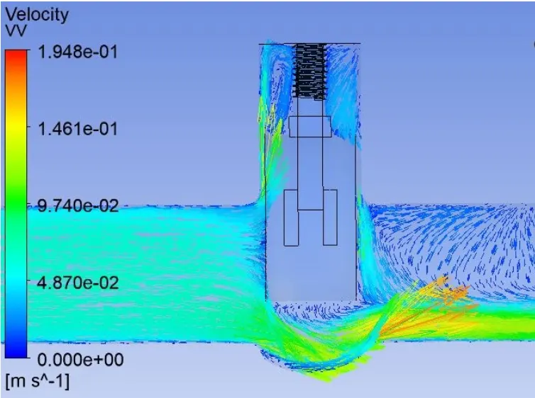
Case-5: 50mm Lift
Flow coefficient and flow factor:
where Q = 0.56379
SG = 1
ΔP = 10
By substituing the above values we get `C_v` = 0.178285
`K_v` = 0.865*0.178285 = 0.154216
Velocity contour:
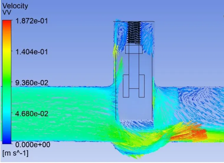
Case-6: 60mm Lift
Flow coefficient and flow factor:
where Q = 0.64398
SG = 1
ΔP = 10
By substituing the above values we get `C_v` = 0.203642
`K_v` = 0.865*0.203642 = 0.176150
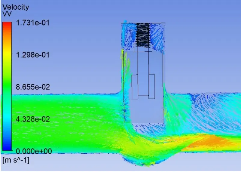
Velocity contour:
Case-7: 70mm Lift
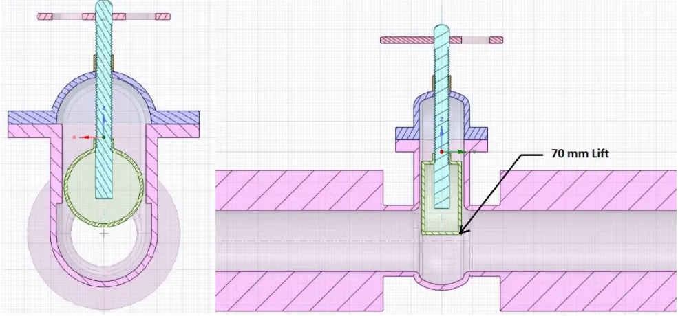
Flow coefficient and flow factor:
where Q = 0.72245
SG = 1
ΔP = 10
By substituing the above values we get `C_v` = 0.228456
`K_v` = 0.865*0.228456 = 0.197614
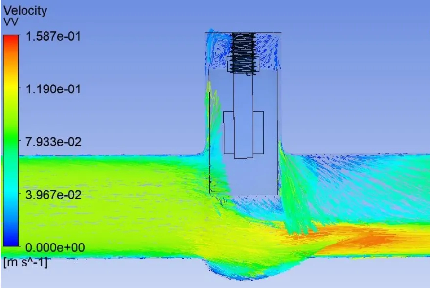
Velocity contour:
Case-8: 80mm Lift
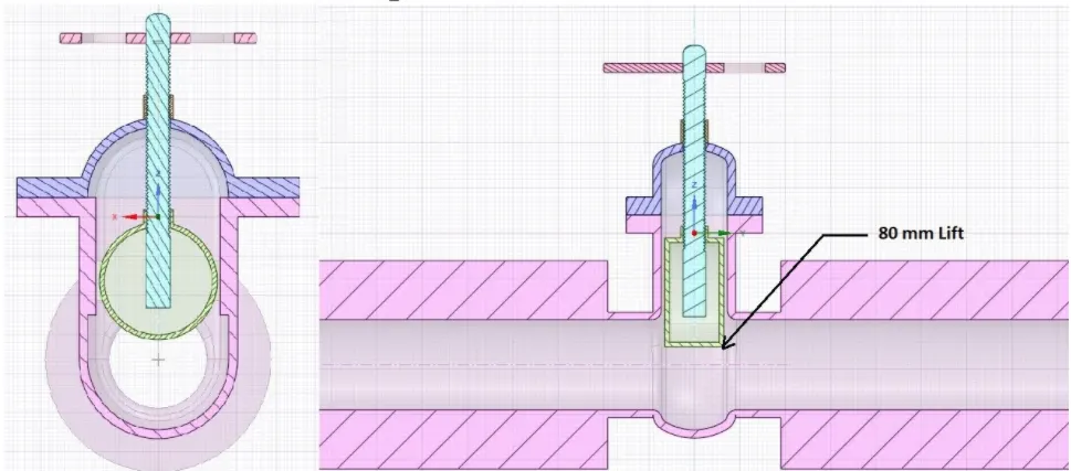
Flow coefficient and flow factor:
where Q = 0.78851
SG = 1
ΔP = 10
By substituing the above values we get `C_v` = 0.249344
`K_v` = 0.865*0.249344 = 0.215682
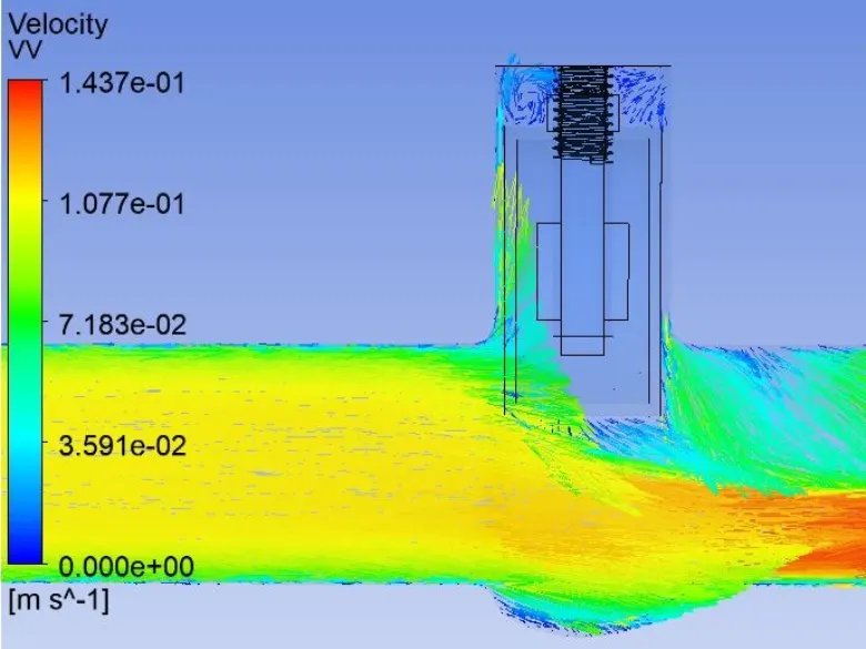
Velocity contour:
Summary:
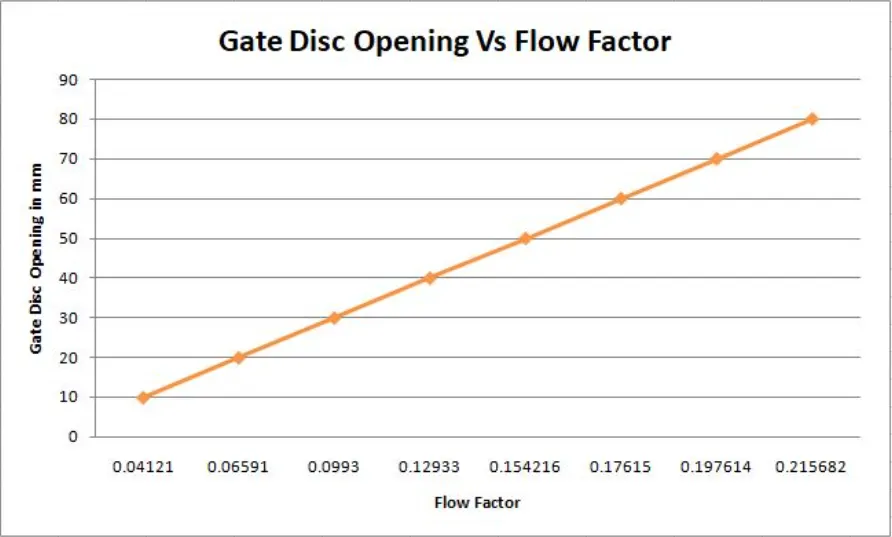
Graphs:
Conclusion:
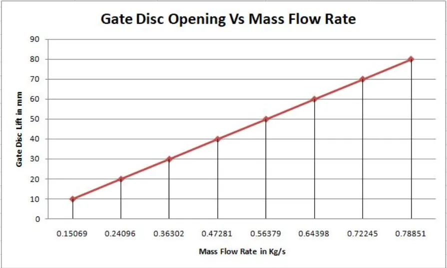
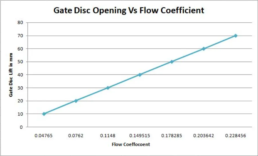
- From the above summary and graphs we can conclude that with increase in the lift of the gate valve, the mass flow rate increases which increases the flow coefficient and inturn increases the flow factor.
- The velocity also increases with increase in the lift of the gate valve.