External Aerodynamic Simulation Over Mercedes Benz Actros Truck using STAR-CCM+
AIM: To Perform External Aerodynamics Simulation over Mercedes Benz Actros Truck using STAR-CCM+
PROCEDURE:
Part-I: Simulating complete model
- The given model is inclined i.e. the container is deviated and has to be made straight.
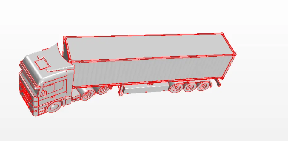
- Inorder to align this part a new cartesian coordinate system is defined w.r.t the joint part that is provided behind the truck.
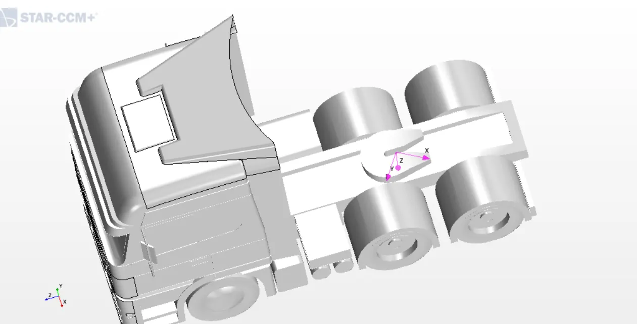
- Now w.r.t the z-axis the container is rotated by giving certain angles and the part is aligned.
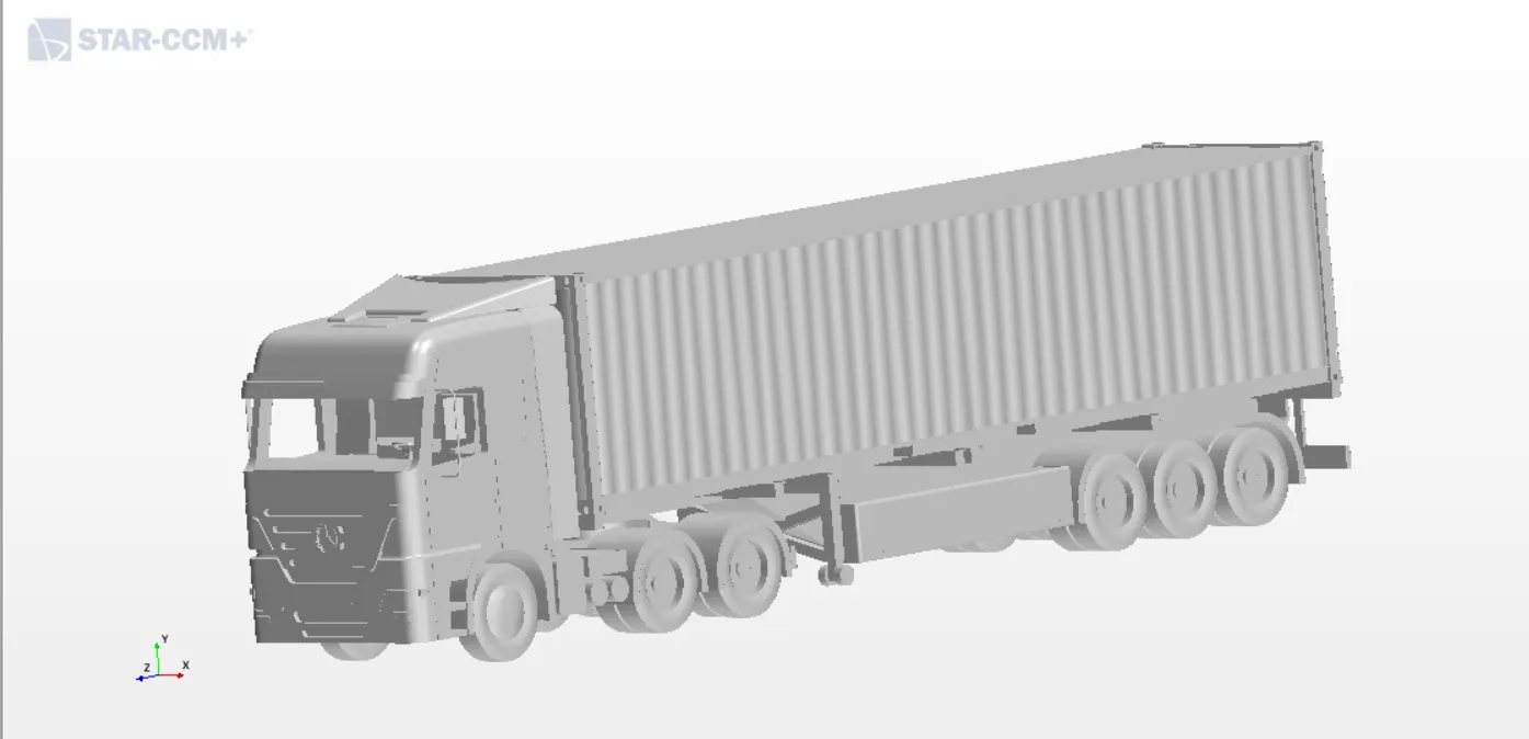
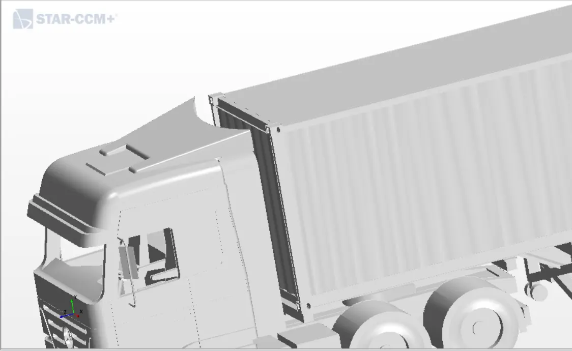
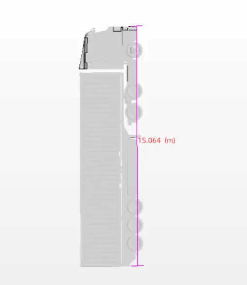
- Then the model is measured using measure option.
- Then the errors are checked if any. It is observed that the windshield and the windows are open and hence has to be closed as this simualtion is an external aerodynamic simulation and this is carried out in Repair surface option.
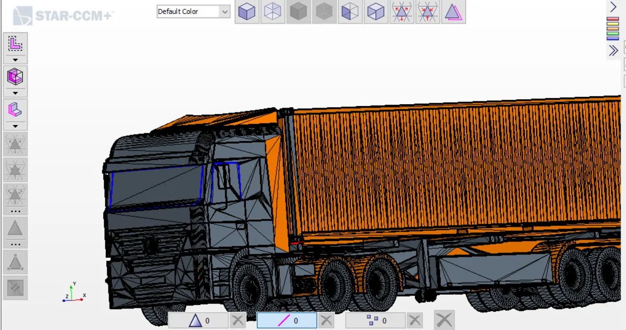
- When the repair surface option is executed then we see that the model has too many surface errors such the penetrations etc.Hence to get rid of these errors the model has to be surface wrapped to proceed for the simualtion.
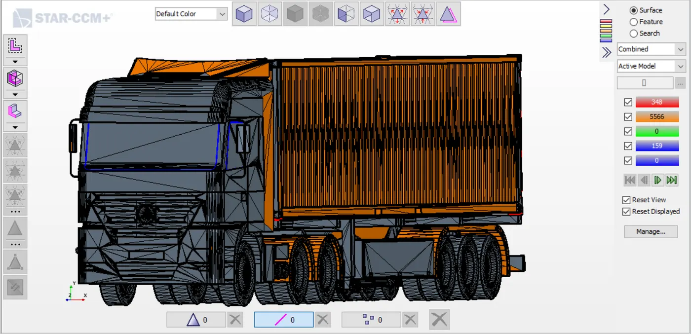
- For the suface wrapper to carry on the base size of 0.01mm is given and is executed.
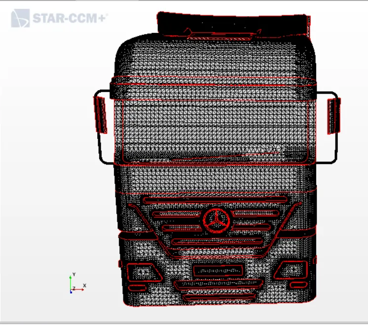
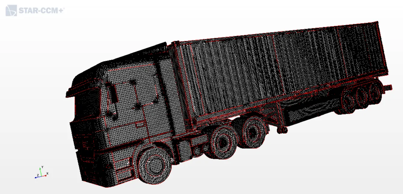
- Now the surface wrapper does a good job in wrapping the model but at some areas it fails and hence in those regions contact prevention is given for the parts those are in contact such as the tyres and rims, grills,logo etc.
- Once the surface wrapper and contact prevention is done ,again the wrapped model is checked for surface errors using the repair surface option. Only face quality and face proximity errors can be there as they will be rectified during the surface remesher operation.
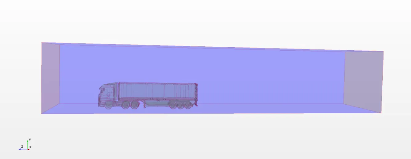
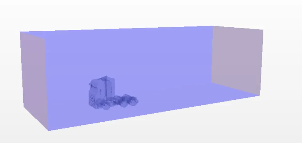
- Now the wind tunnel is created for the truck model where the rear distance of the truck is twice the frontal distance. The block is given the region names such as Inlet.Outlet,and Sides.
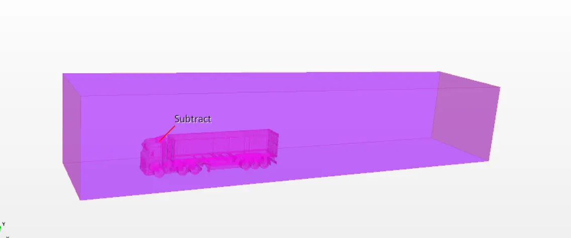
- Now the boolean subtract operation is done inorder to subtract the CAD volume from the block since this is an external aerodynamics simulation and the obtained part is Subtract.
Boundary Conditions:
The boundary condition are given to the subtract model as follows:
- Inlet - Velocity inlet
- Outlet - Pressure Outlet
- Sides - Symmetry
- Floor - Wall
- Truck Model - Wall
Meshing:
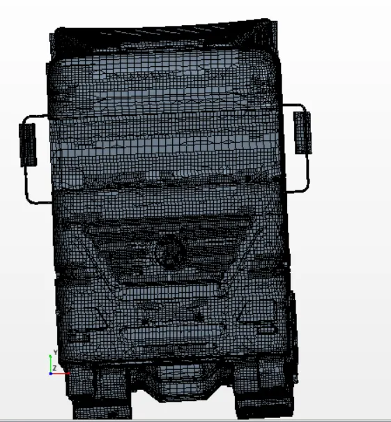
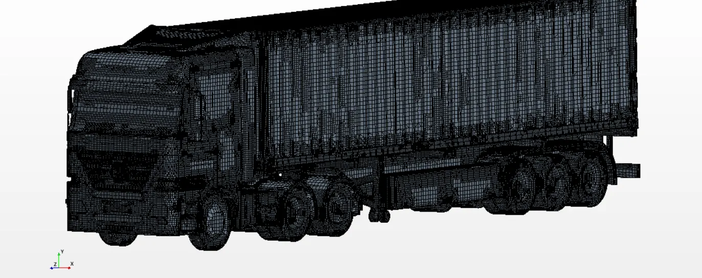
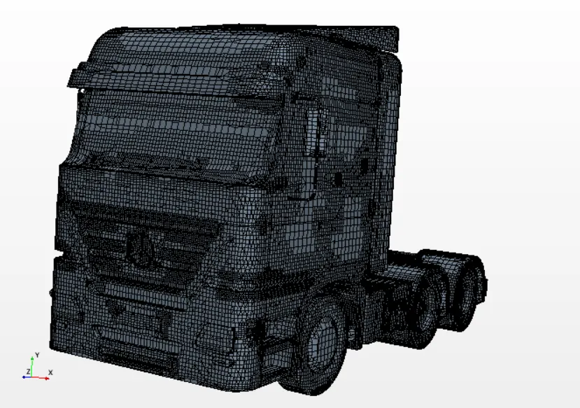
- Now the subtract model is meshed using the following mesh techniques:
- Surface Remesher
- Automated Surface Repair
- Trimmed cell mesher
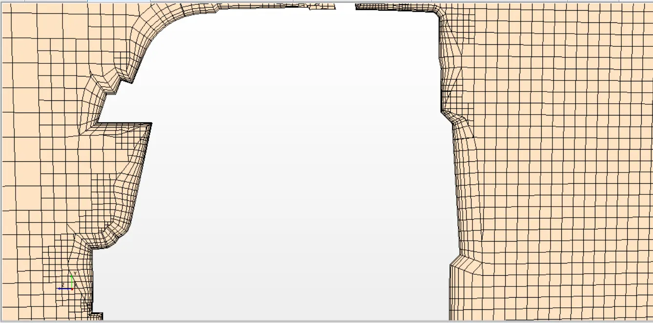
- Prism Layer mesher
Default controls:
- Base size - 0.3m
- No.of prism layers - 6
- Prism layer thickness - 50% = 0.15m
- Maximum core/ Prism transition ratio - 2
- Volume growth rate - medium
- Maximum cell size - 800% = 2.4m
Custom controls:
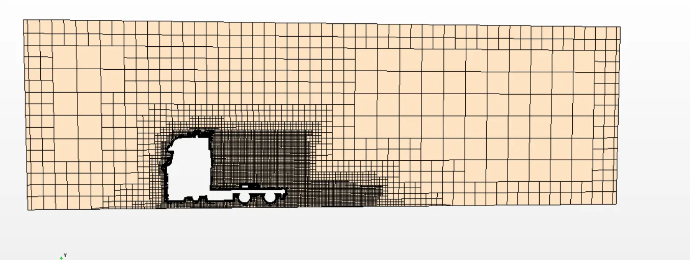
- The wake refinement is done model by selecting the entire truck model.
- the wind tunnel is given custom control with 250% of base size i.e. 0.75m.
The automated mesh is as follows:
Section Plane view:
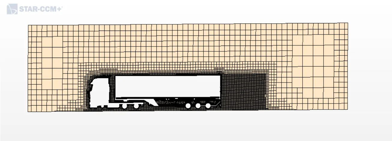
Section plane view with prism layers:
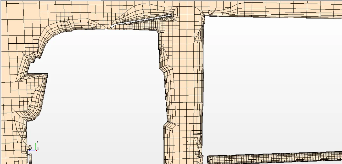
Physics Continua:
The selected physics models are as follows:
- Space - 3 Dimensional
- Time - Steady
- Fluid - Gas
- Flow - Segregated
- Equation of state - Constant density
- Viscous regime - Turbulent
- RANS model - Realizable K-Epsilon
- Wall treatment - all y+
Physics values:
- Inlet velocity - 33.33 m/s
- Outlet pressure - 0 pa
Reports and Plots:
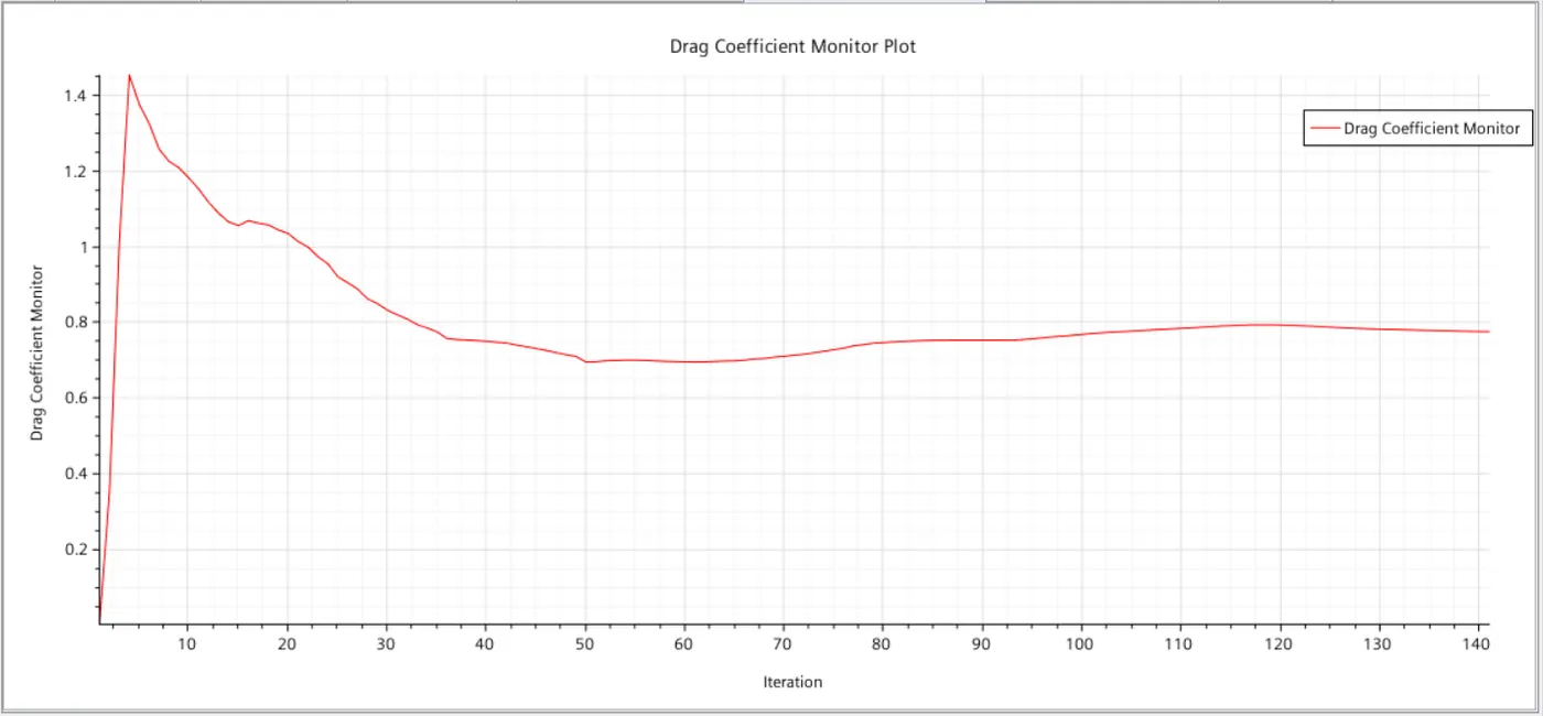
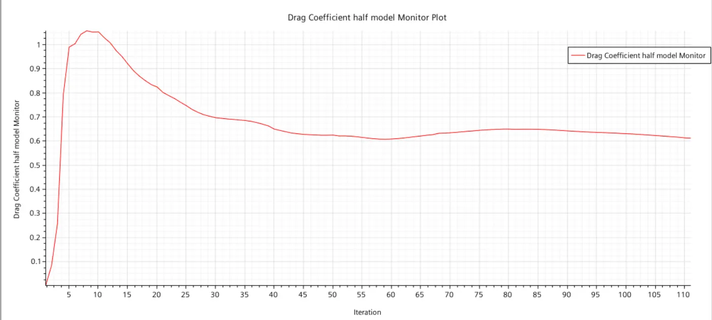
- Drag coefficient values are calculated and plotted by giving the direction of force as -z.
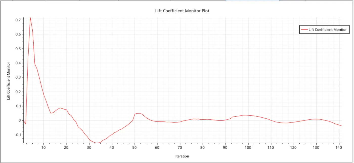
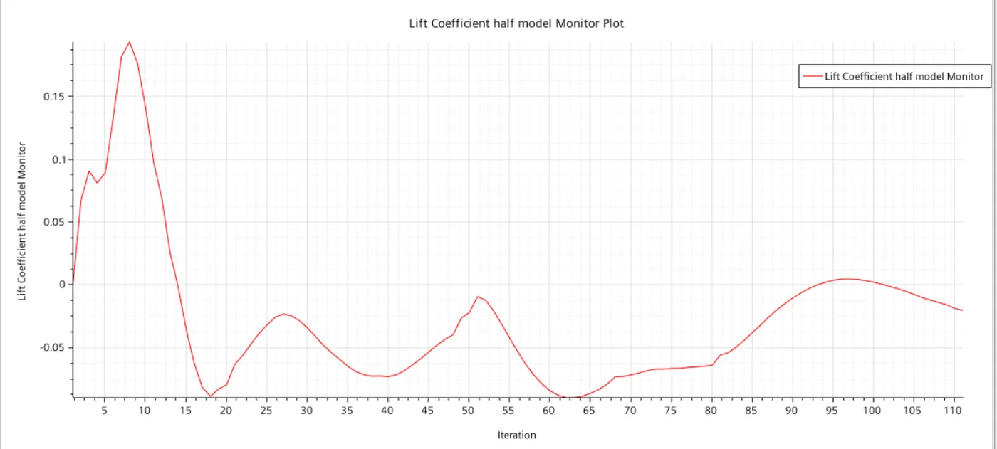
- Lift coefficient values are calculated and plotted by giving the direction of force as +y.
- Outlet velocity is also calculated and plotted.
The reference values for the above plots are:
- Area = 9.94 m^2 (This is calculated by the software by running a report named frontal area and selecting the front part of the model.)
- Density = 1.225kg/m^3
- velocity = 33.33 m/s
Results:
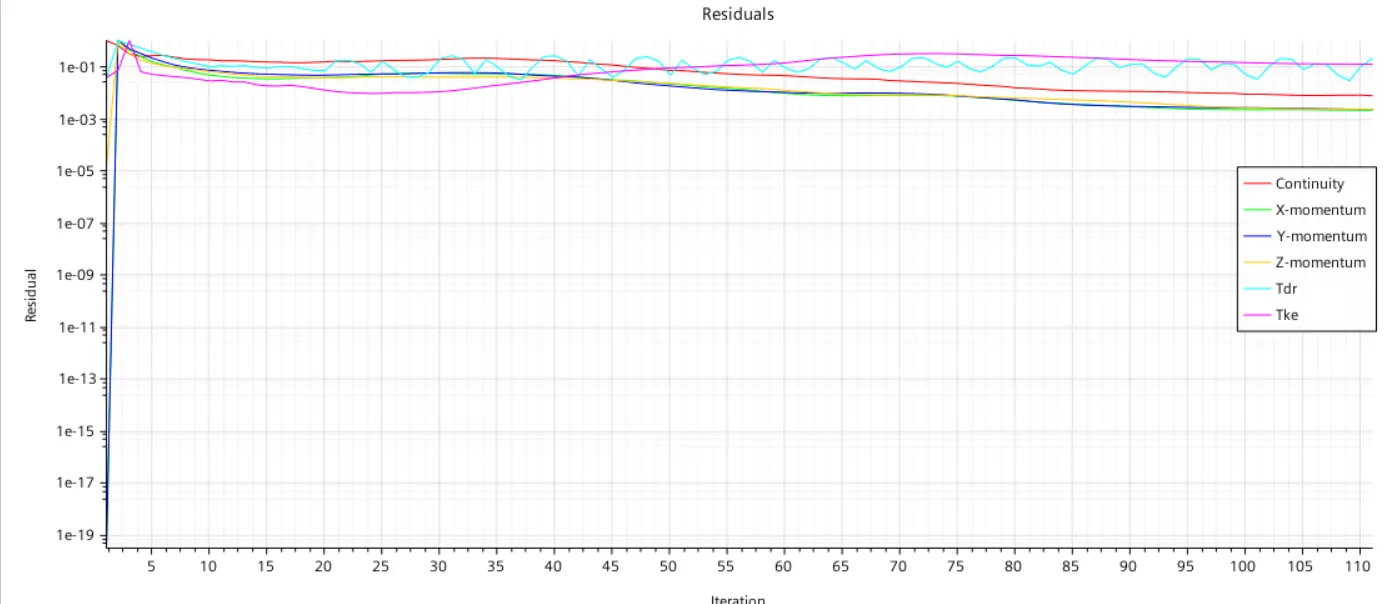
1. Residuals:
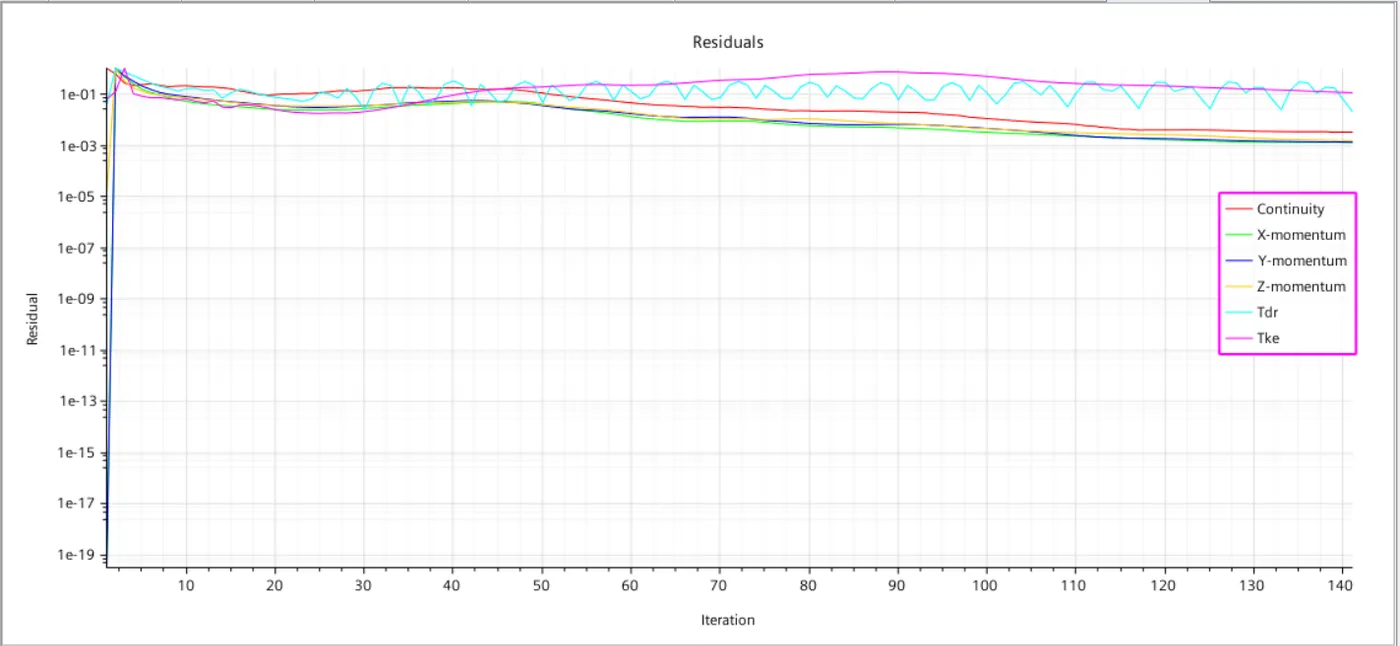
2. Drag coefficient:
3. Lift coefficient:
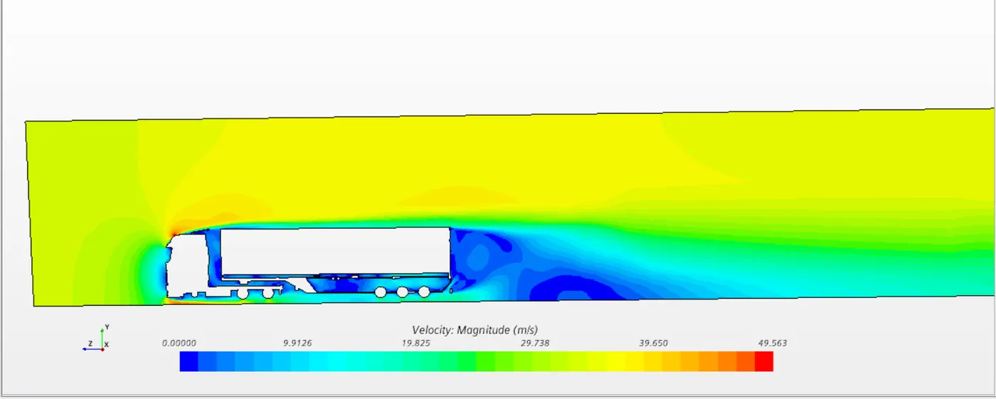
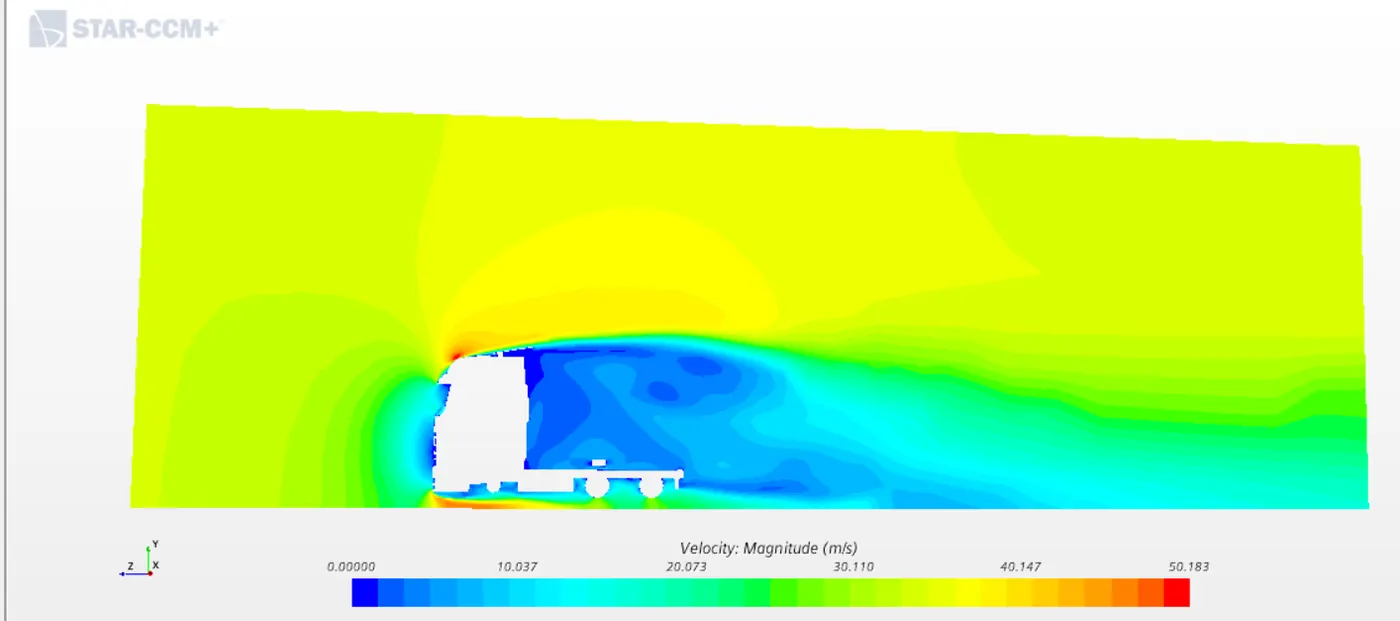
4. Velocity contour:
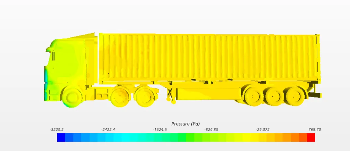
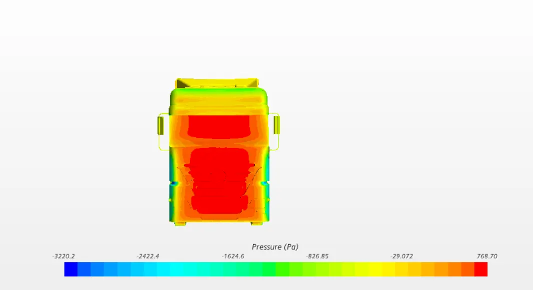
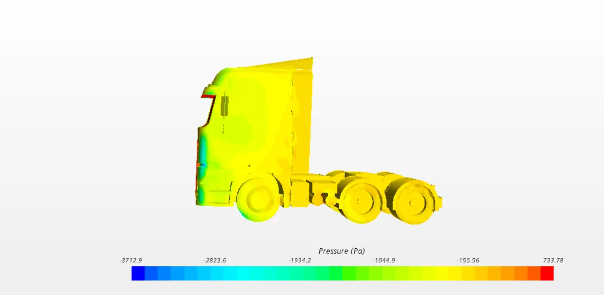
5. Pressure contour:
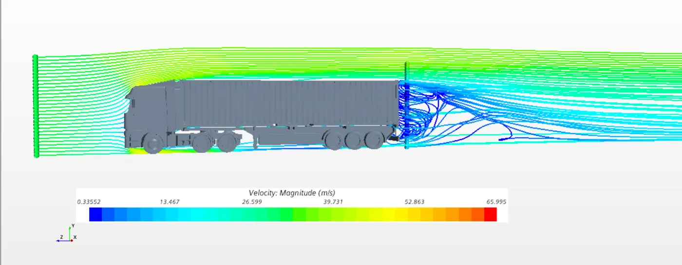
6. Streamlines:
7. Streamlines animation:
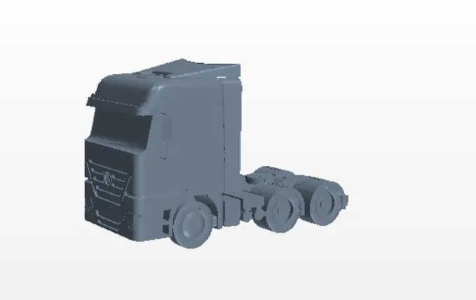
Part - II: Simulating the model only with the tractor i.e. without trailer:
The mesh size and all other aspects are same as the above model.
Geometry:
Subtract:
Volume mesh:
Section Plane view:
Section plane view with prism layers:
Results:
1. Residuals:
2. Drag coefficient:
3. Lift coefficient:
4. Velocity contour:
5. Pressure contour:
6. Streamlines:
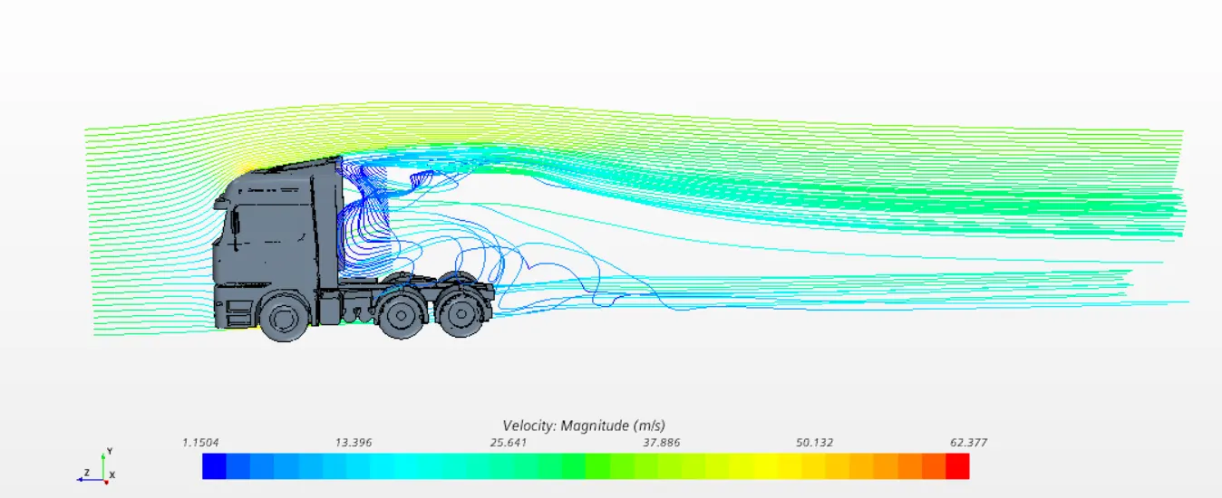
7. Streamlines animation:
Conclusion:
- The drag in the 1st case is 0.8 and in the 2nd case is 0.6. Hence due to the absence of the trailer the drag has decreased.
- Velocity and pressure remains almost the same in both the cases.
- A lot recirculation can also be seen in the wake region.