Flow Simulation over a NACA Airfoil
Aim: The goal of the project is to simulate the flow over a NACA symmetric airfoil for various angles of attack and interpret the results.
Background:
An airfoil or aerofoil is the cross-sectional shape of a wing, blade, or sail. An airfoil-shaped body moving through a fluid produces an aerodynamic force. The component of this force perpendicular to the direction of motion is called lift. The component parallel to the direction of motion is called drag.
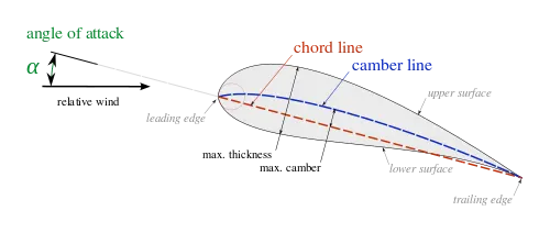
An airfoil generates different lift and drag forces for every angle of attack. Both the forces are very low (or zero) for zero angle of attack and keep increasing as you angle the airfoil further to the flow direction.
In this project, we will be analysing the forces for angles of attack from 0 to 10 degrees at steps of two. We will then plot the trend of the forces.
Procedure:
- Extract the 100m chord length NACA 0017 plot from the Airfoil Database site in excel format.
- Sort the excel data of x and y coordinates into columns in a notepad file, add a z column of zero values.
- In Solidworks, "Insert curve" and upload the file. Ensure that the file is set to the MKS system before uploading.
- Once inserted, "Convert entities" and create an extrusion of 0.2m wingspan.
- Add rotation of -2, -4, -6, -8, and -10 degrees for each analysis when making the sketch from the "rotate sketch" option.
- In fluid simulation, select "Time-Dependent Study" with the following details:
- Total analysis time = 5 seconds
- Tim step = 0.5 seconds
- Select Air as the fluid, and add an x-axis velocity of 600 m/s.
- In the computational domain, select the 2D option and the following domain dimensions:
- X = 10/-5m
- Y = 5/-5 m
- Z = Leave as is since 2D has been select on the XY plane
- Increase the refinement of the mesh and add a surface mesh along the airfoil surface.
- Run the simulation for each of the angles of attack and plot the trend.
Results:
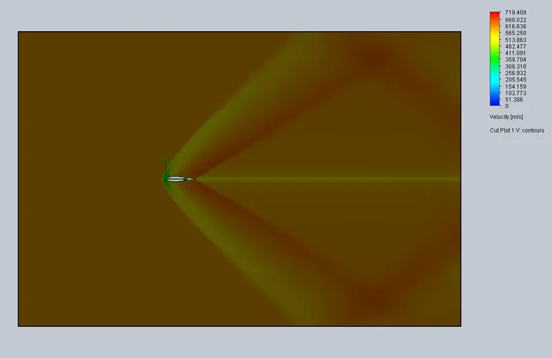
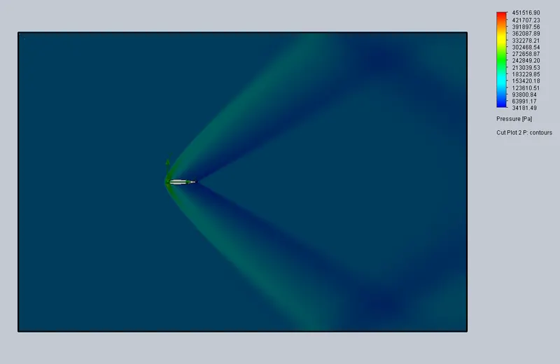
- AoA = 0:

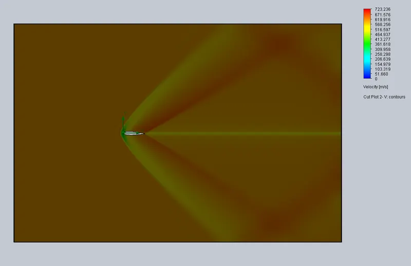
- AoA = 2:

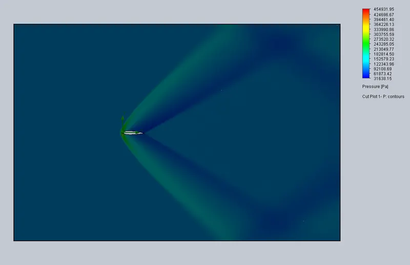
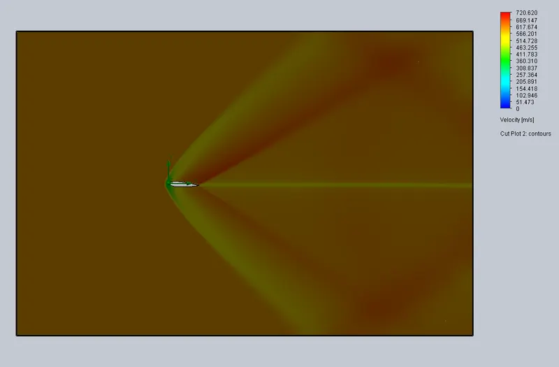
- AoA = 4:

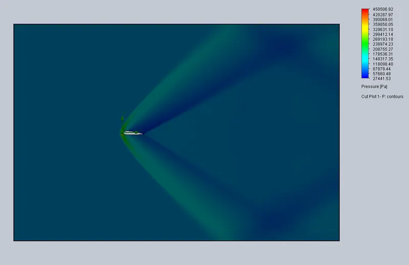
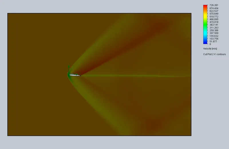
- AoA = 6:

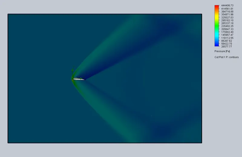
- AoA = 8:

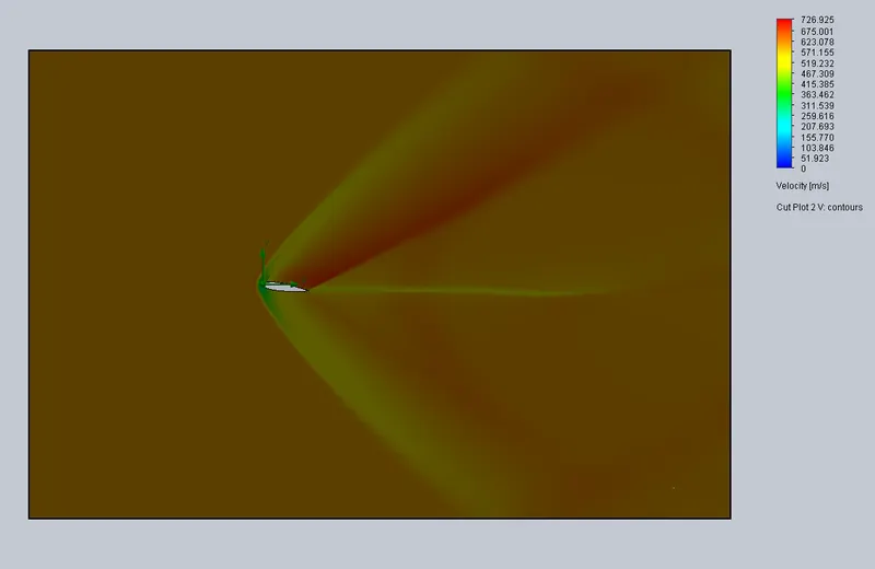
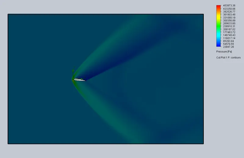
- AoA = 10:

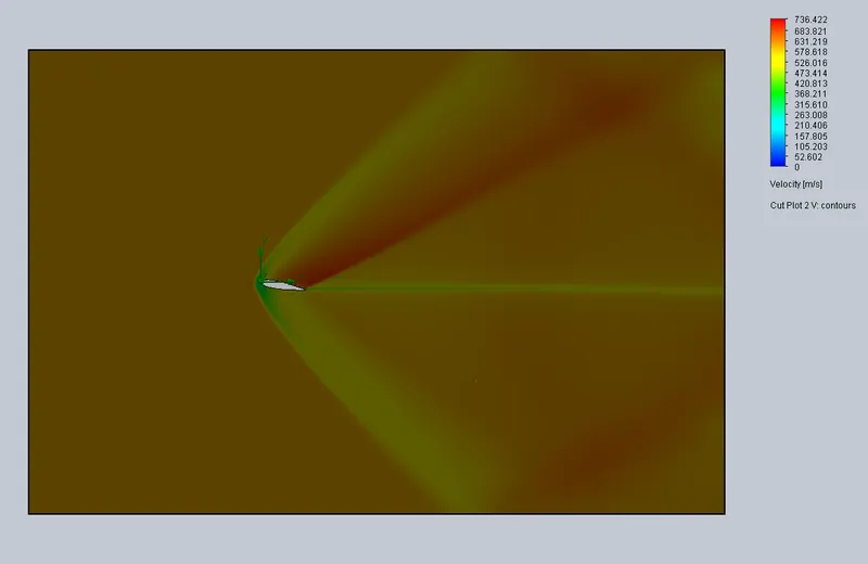
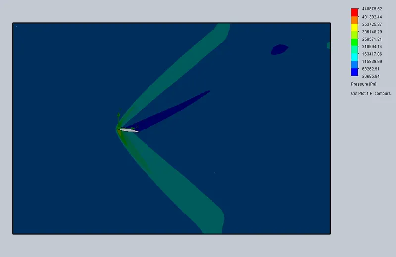
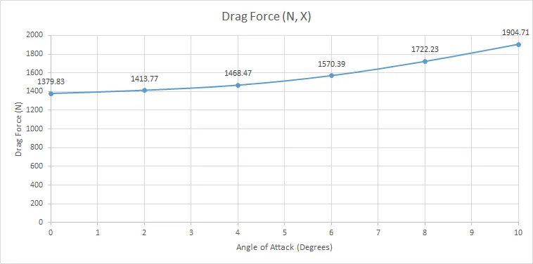
Drag forces vs Angle of Attack:
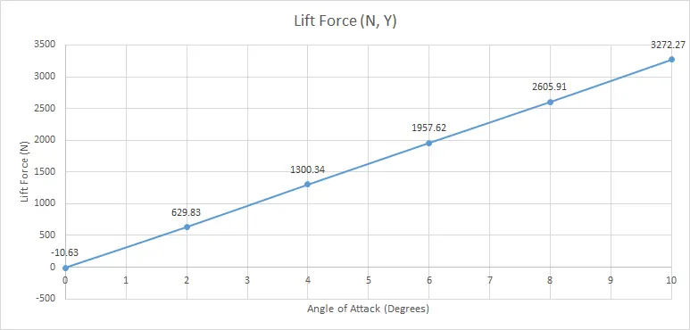
Lift Force vs Angle of Attack:
Conclusion:
As seen by the trend of the Drag and Lift forces vs the AoA graph, both the drag force and lift force increase with an increase in the angle of attack. The lift force is negligible for zero angles of attack as this is a symmetric airfoil. The value of drag force for zero AoA never reaches convergence even after over a thousand iterations and keeps fluctuating from negative to positive. Due to its symmetric nature and zero AoA, the 0017 airfoil generates negligible lift force. Also, the symmetry of the velocity and pressure profiles is only observed for zero AoA.
Adding a local surface mesh on the airfoil surface where contact is made with the flow helps achieve close-to accurate results.
Despite having a computational boundary of 10 times the chord length downstream and 5 times above and below, there is a reflected wave in the wake region indicating that the computational boundary could be greater.