Final Project: Electric Rickshaw modelling
PROJECT REPORT
------DESIGN OF MATLAB MODEL OF AN ELECTRICAL RICKSHAW-------
Introduction to the project
What are electric riskshaws?
Electric riskshaws are one type of the Electric vehicles where it has 3-wheeled vehicle and those are powered by motors and battery unit and motor controller are same which are used in general electric vehicle. These electric riskshaws's chassis consists of 3 wheels basically. Mostly these vehicles are made using an INduction motor and rear wheeled powered. These riskshaws are developed for carrying moderate loads and to travel over moderate distances.
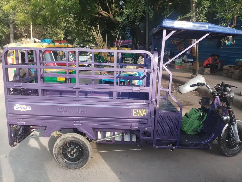
fig(A) E-riskshaw vehicle
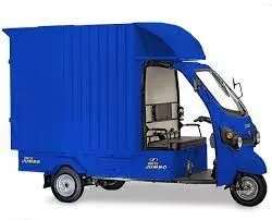
fig(B) Kinetic green E-riskshaw vehicle
Future of EV
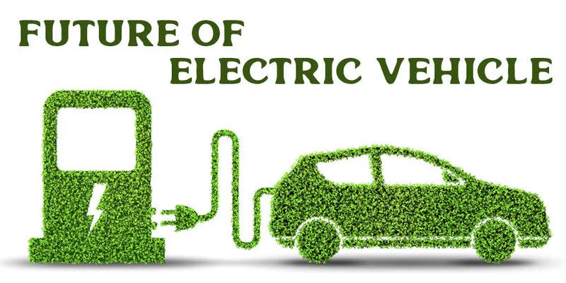
When there is a boon in software industry in earlier 20s then many had questioned the boon and started ignoring it. As of now this EV is in boon and it would continue and lead the path for next 10 to 30 years from now. Because of the cost savings and low maintenance moreover these vehicles are more capable in load and stylish look appearence, it can replace combustion vehicles which causes polution over the world. Due to increase in fuel prices, subsequently the EV rise over the world would also be propotinate.
Abstract of the project
Objective of Electric riskshaws
E-rickshaws have proven to be a great last-mile commute solution for Indian roads. powered by batteries, e-rickshaws are a zero-pollution option. E-rickshaws are significantly cheaper than the conventional last mile solutions such as autos which are the second most affordable mass mobility option. e-rickshaws are easier to operate and maintain than conventional autorickshaws. These have the capability of essentially decreasing city contamination by having zero tail pipe discharges.
These EVs are the one thing which can easily gone through the middle class man brain in order to manage his/her wallet. The EVs production and management has now good market value in automobile industry.
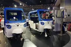
Design of Electric riskshaws
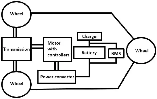
As the EVs are designed with motor, motor controllers, battery unit, these are the main components which are embbed in a EV. And same important components are also used in electric riskshaw. The only difference in 2W, and 3W EVs would happen in selection of motors depending on the load and travelling range.
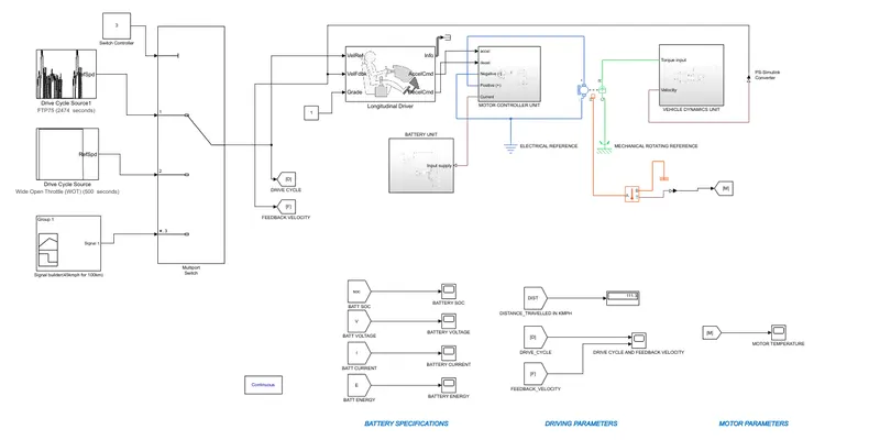
The wheels in electric riskshaws are rear wheel driven, means the motor propulsion is been driven by the motor is been atthaced at the rear wheel gear. The electric riskshaw here I had designed using a permanent magnet motor and a lithium ion battery as shown below. The below block diagram indicates the electric riskshaws design.
Review of project
Components used
Drive cycle: drive cycle is the block that refers to the vehicle speed in terms of road and other driving conditions while driving a vehicle. In Simulink the drive cycle is default set to FTP drive cycle, but if we want we can set any other drive cycle which is relatable. Generally this drive cycle generates random longitudinal drive cycle, in some cases it is required to employ user-defined drive cycle also it is possible, by clicking add new data which adds new drive cycle data from the external file source.
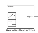
Here there is a requirment of to use any 3 types of drive cycle sources. So the mostly avail drive cycle is FTP drive cycle and WOT cycle. So I had employed 'signal builder' for generating a custom drive cycle without using excel sheet data importing. Respective images are attached below with their run time and other system level configurations as well.
System level configurations of FTP drive cycle
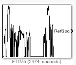
fig(a) FTP75 drive cycle runs for 2474 seconds
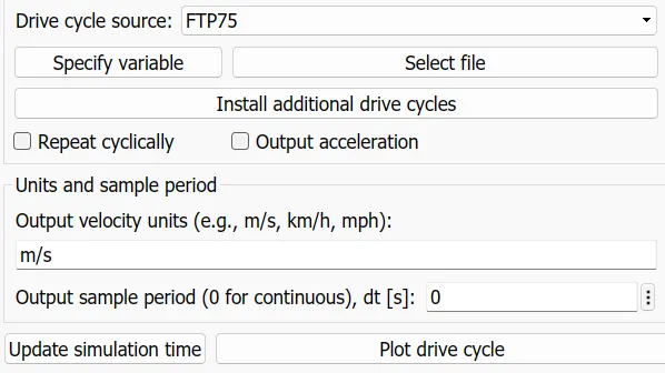
System level configurations of WOT drive cycle
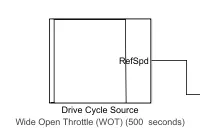
fig(b) WOT drive cycle runs for 500 seconds
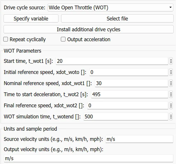
System level configurations of Custom drive cycle using "Signal Builder" block
fig(c) Custom drive cycle runs for 110 seconds
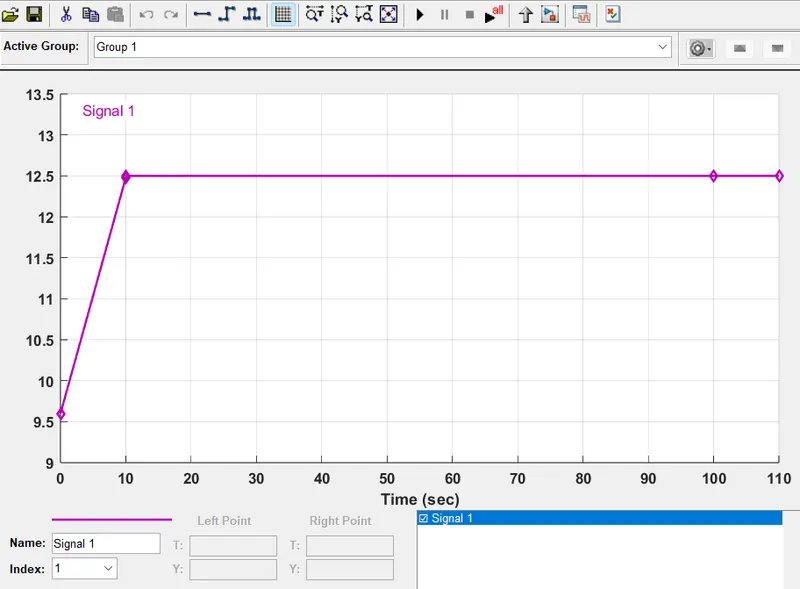
fig(d) Signal builder block response from the data assigned considering constant type signal
Multiport switch:
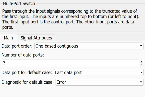
This a type of switch which pass through the input signals corresponding to the truncated value of the first input. The inputs are numbered top to bottom (or left to right). The first input port is the control port. The other input ports are data ports.
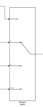
fig (a) Multi port switch block image
Model system configurations of 'Multi port switch' block
Motor: Here in this project I had used permanent magnet brushed type DC motor which has 4 ports. This is the main component in the design of the EV rickshaw model. It has four ports which are positive and negative for the motor positive and negative terminals and it has R and C ports which indicates the mechanical translational rotating port and mechanical reference port respectively.
This block can be implemented with the temperature port which is used for temperature meauring purposes. The port indicates the motor temperature while running.

Fig(a) DC motor block with thermal block
System level configurations of DC motor block
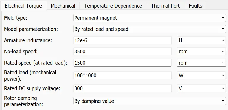
fig(b) DC motor electrical parameters
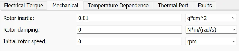
fig(c) DC motor mechanical parameters

fig(d) DC motor temperature parameters
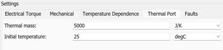
fig(e) DC motor thermal port parameters

fig(f) DC motor faults parameters
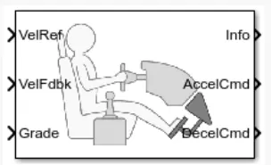
Longitudinal Driver: this Longitudinal Driver is the block that usually does the same work which a driver does in practical scenarios based on input references and feedback of velocity taken from the drive cycle and output velocity of the vehicle. In simple it accelerates and decelerates the vehicle by referring to the vehicle’s velocity and drive cycle references. Basically, it has 6 terminals where vehicle reference is connected to drive cycle and vehicle feedback is connected to vehicle output velocity terminal. Grade is the terminal is an input gradability terminal of the vehicle travelling. Acceleration and deceleration commands are connected as per model requirements to control the vehicle speed.
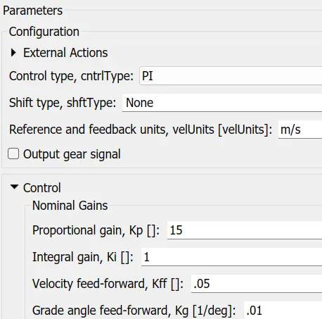
System level configurations of Longitudinal driver block
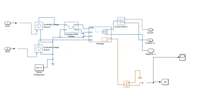
Motor controller subsystem: this is the custom subsystem block which is made to embed all the blocks to a subsystem to control the motor output parameters. This subsystem block represents motor controller which is the “Brain of the EV” . this subsystem block contains controlled voltage source blocks and an H-bridge block to control the motor’s rotation. PWM voltage block which is used as an input parameter to the H-bridge block with thermal port for measuring the temperature of the controller of the motor.
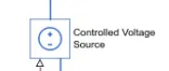
Controlled voltage source block: this is the block which controls the voltage parameters with specific voltage. Here it plays like accelerating and decelerating parameter.
Controlled PWM voltage block: it is just like the PWM voltage source where output voltage is “0” when pulse is low, and here it is used to power the h-bridge block and gives PWM input to the h-bridge block. It has 4 terminals which need the reference voltages. PWM is the output port that is connected to the h-bridge circuit.

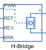
H-bridge circuit: here the H-bridge circuit is used as a motor driver where it requires a PWM signal as input. The H-Bridge block output is a controlled voltage that depends on the input signal at the PWM port.
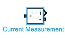
Current sensor: it is the measuring unit that is used to measure the current value of the circuit where it is connected. It should be connected in series to the circuit to measure the current value.
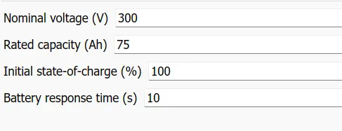
Battery subsystem: It is a user-defined subsystem that embeds all the battery-related components. It has a battery pack and it measurement display. Here in this subsystem, there is a SOC estimation system that determines the state of charge of the battery’s parameter.
The battery pack which is been used is 'lithium-ion' battery pack where the capacity is set to '70ah' and the battery volatge is set to '300v' output.
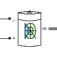
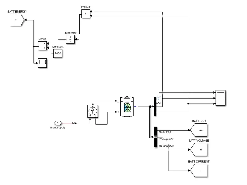
System level configurations of Lithuim ion battery
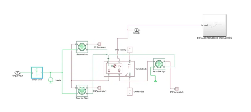
Vehicle subsystem: it is also a user-defined subsystem that embeds all the vehicle related components. In this system we have tyre of front and rear wheel alignment and main block called ‘vehicle body’ which used to move the tyre alignment from the propulsion came from the motor. The design is based on the electric rickshaw. so the wheels are used only three and rear wheel powered as required.
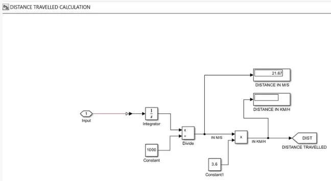
Distance travelled unit: This unit system is used to calcuate the distance travelled by the vehicle by using vehicle's motor propulsion and battery pack. THis subsystem is created to differentiate the measurement unit and vehicle alignments. The default calucaltion is done in M/S, to calucate it into KM/H , I had used product block to convert it into KM/H, to mutlipy it with 3.6 to get kmph units.
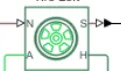
Tire block: the tire block represents the tire alignment of the vehicle. It has 4ports which must be refers to mechanical rotating translational unit and normal forces acting on the tire. Where N is the connected to rear wheel thrust or front wheel thrust alignment of the vehicle. S is the slip factor ogf the tire and it can be connected to terminator.
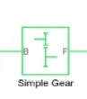
Gear box block: this block is the gear box which enables the normal rotations to a specific gear ratio and works as same gear box used in cars and bikes. Where it has two ports namely B and F ports , these are used to conversion of gear ratio. B is the input port of the simple gear and F is the output port of the gear and it is connected to vehicle propulsion shaft.
Matlab simulink model for "Design of Electric riskshaw" project
Results
-----------CASE1-----------
Using FTP drive cycle (1st drive cycle)
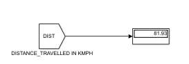
Distance travalled in Km by the vehicle:
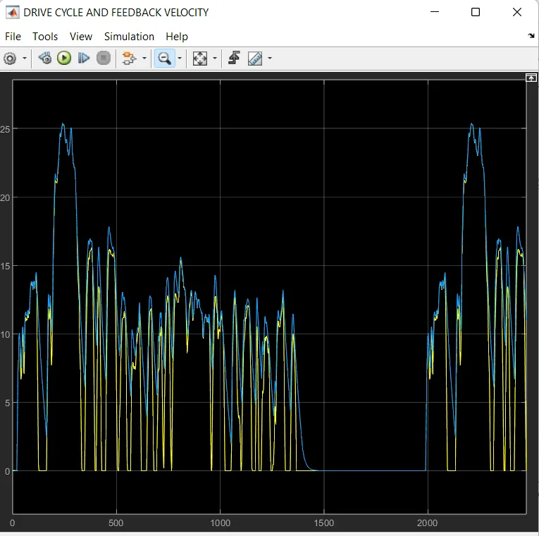
Drive cycle and feedback velocity response:
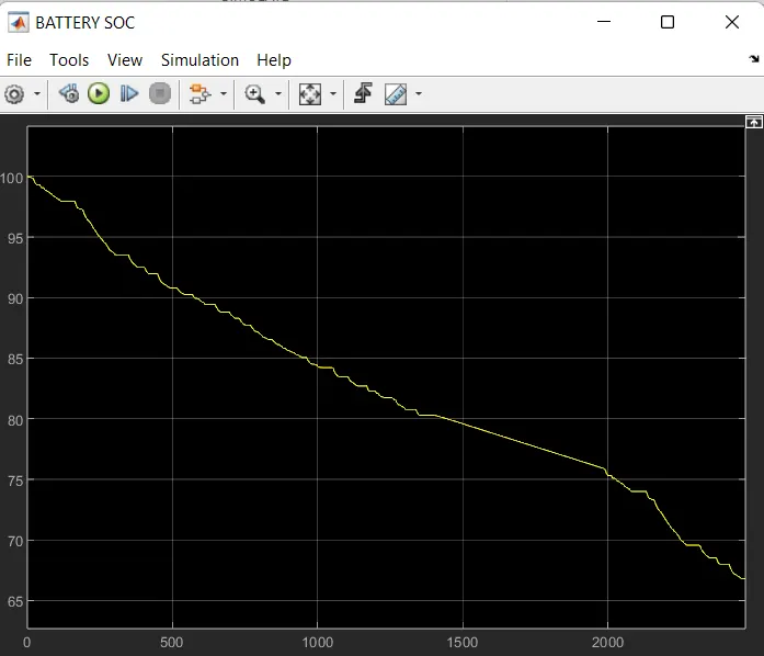
Battery SOC response:
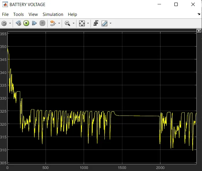
Battery voltage response:
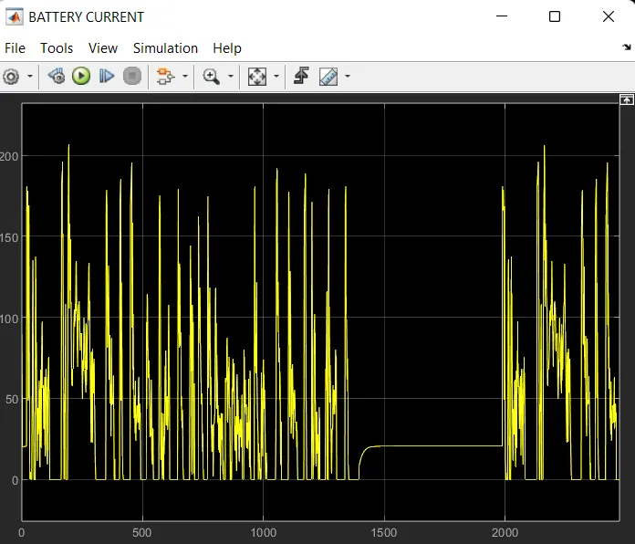
Battery current of the vehicle response:
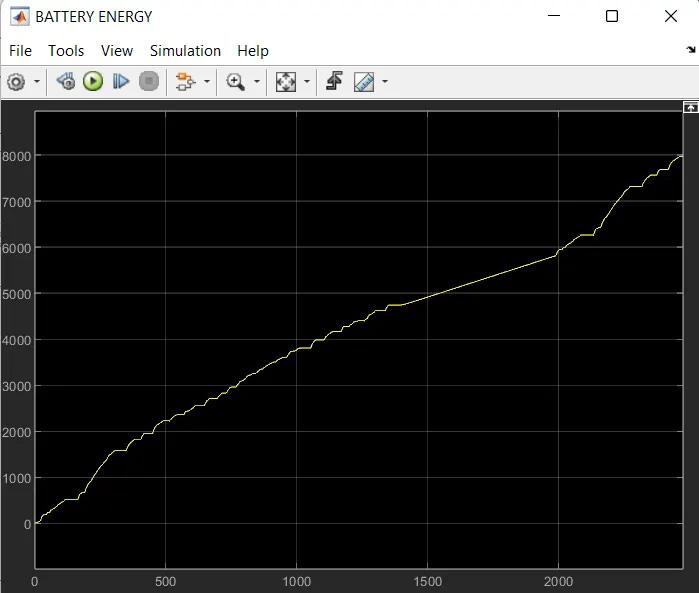
Battery energy consumption of the vehicle response:
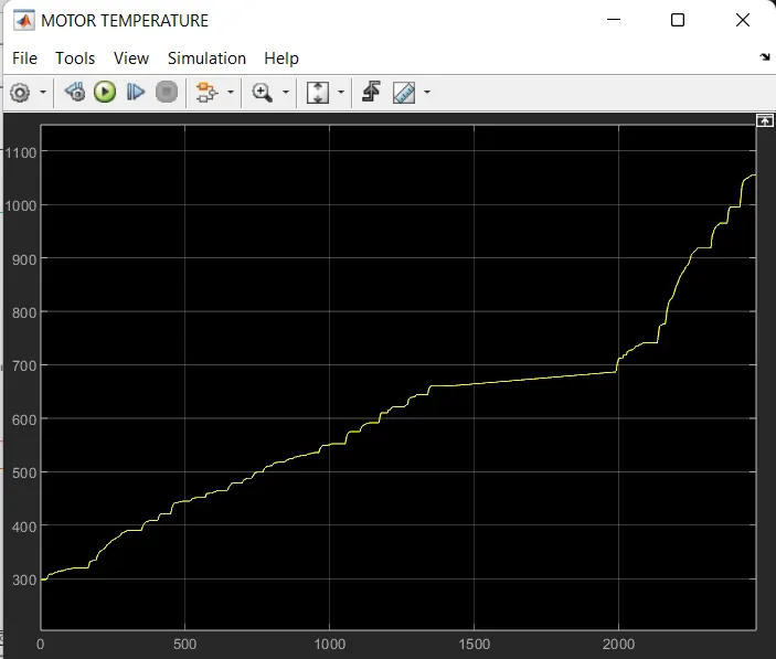
Motor temperature while running:
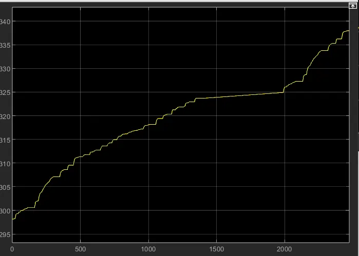
Motor controller temperature while operating:
-----------CASE2-----------
Using WOT drive cycle (2nd drive cycle):
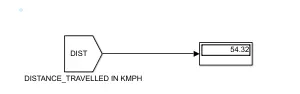
Distance travelled by the vehicle in KM:
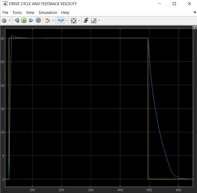
Drive cycle and feedback speed of the vehicle:
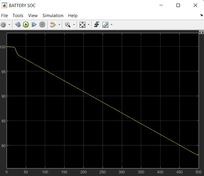
Battery SoC response:
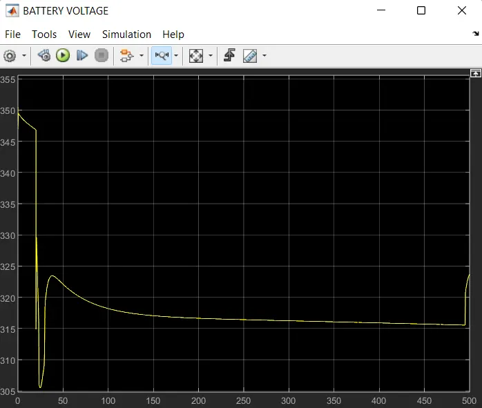
Battery voltage response:
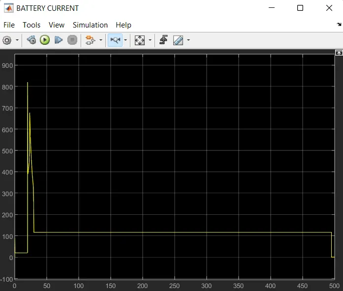
Battery current reponse:
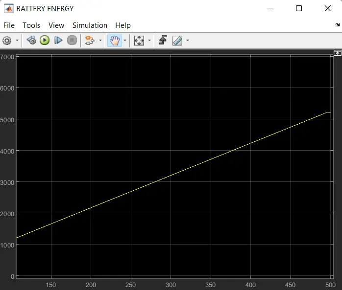
Battery energy consumption response:
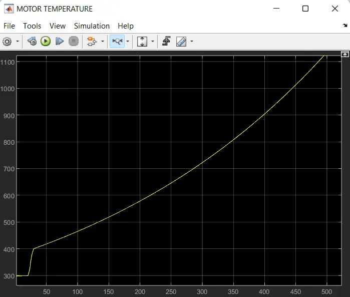
Motor temperature of the vehicle while moving:
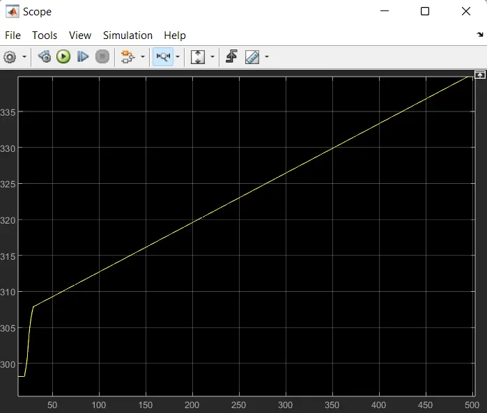
Motor controller temperature:
-----------CASE3-----------
Using Custom drive cycle (3rd drive cycle):
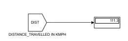
Distance travelled in KM by the vehicle:
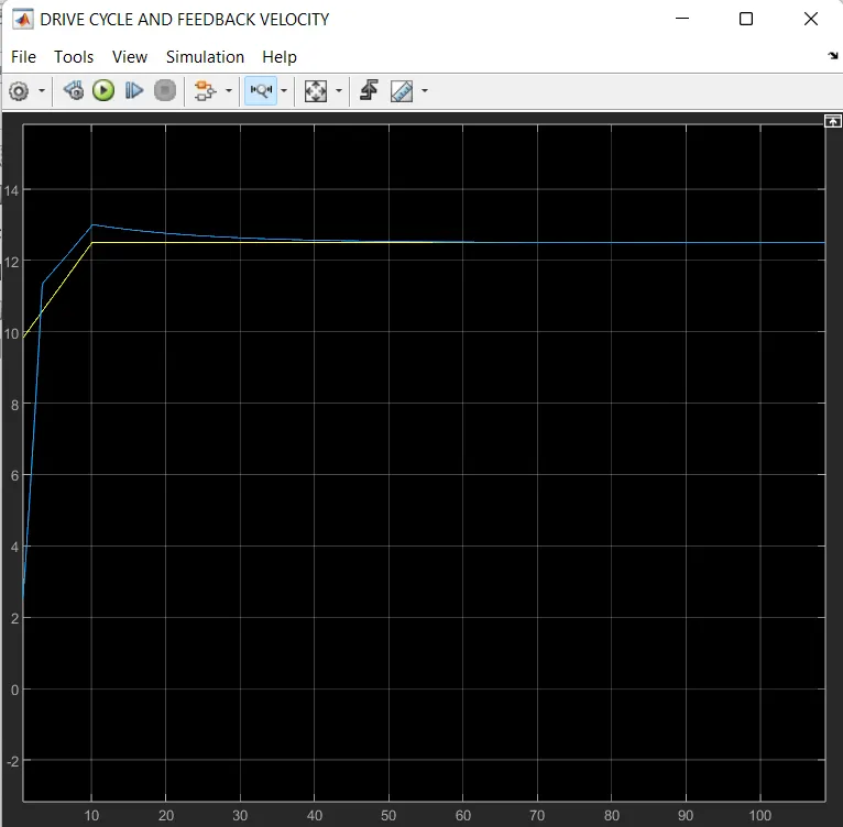
Drive cycle and feedback speed of the vehicle:
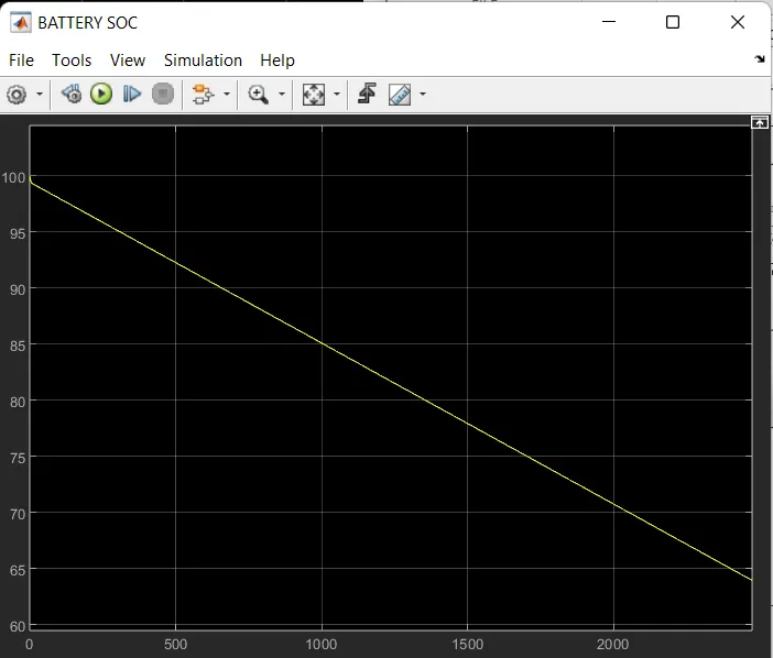
Battery SoC response:
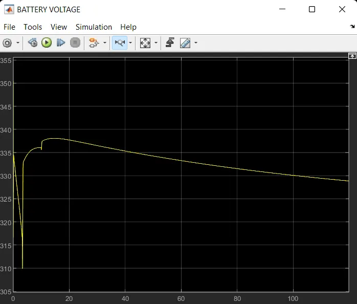
Battery voltage response:
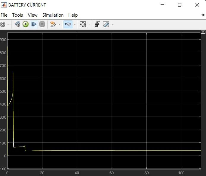
Battery current response:
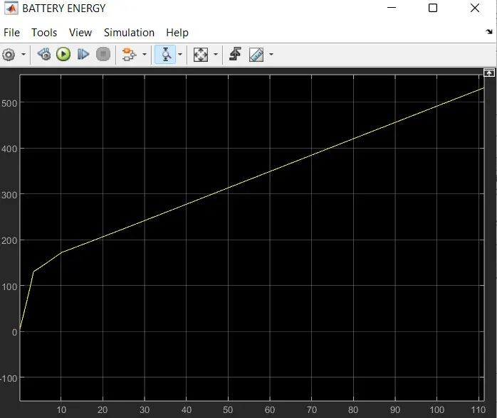
Battery energy consumption response:
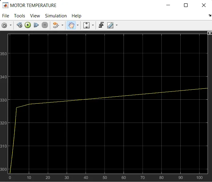
Motor temperature while travelling:
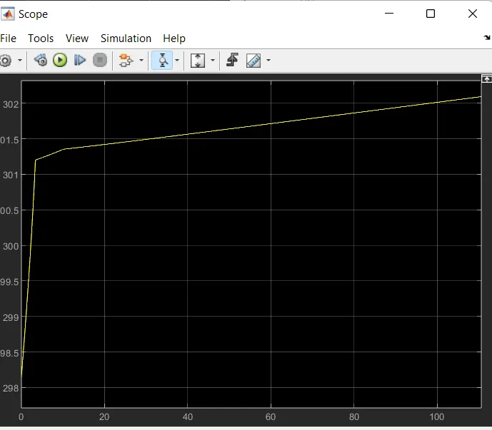
Motor controller temperature while operating:
Observations
- As insisted that to develop a MATLAB model of an electric rickshaw (three wheel passenger vehicle) as per requirements are satisifed.
- As the electric rickshaw is made of three wheel and Rear wheel powered by PM brushed type motor which is basically of DC motor.
- Assuming the efficiency points of motor controller and motor are also discussed above.
- The inputs and assumed data are Made an excel sheet and attached.
- As we had employed three drive cycles FTP, WOT , custom signal builder drive cycles and their energy consumption, temperature rise and other outputs are observed and attached respectively.
- So there is a other requirement which is, for 100 km constant speed driving at 45 kmph is also achevied by the signal builder block. As the drive cycle data is been assigned to the builder block and thus it generated the drive cycle data.
- The vehicle is been travelled for 100km at 45kmph which is converted to m/s which gives 12.5m/s which can be observed in the plot.
Conclusion
The design of the electric rickshaw is been developed and tested using three drive cycles which are FTP, WOT drive cycle and custom drive cycle and in all drive cycle the feedback speed and drive cycle velocity are matching with each other.
FTP drive cycle:
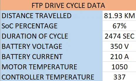
By using the FTP drive cycle, The distance travelled by the vehicle is 81.93 kms. Both the fedback velocity and drive cycle pattern are matching with each other. The battery SoC is also observed and conclude that the left over charge in the battery is almost 67% percentage and exhausted 33% of charge to travel upto 2474 seconds of cycle duration. The battery voltage has touched the peak of 350v of battery voltage measurment and current of 210 amps is the highest peak value of current measure. when it comes to energy consumption is almost 8000 watts. The temperature of the motor has reached to 1050 and 337.
WOT drive cycle:
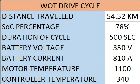
By using the WOT drive cycle, The distance travelled by the vehicle is 54.32 kms. Both the fedback velocity and drive cycle pattern are matching with each other. The battery SoC is also observed and conclude that the left over charge in the battery is almost 78% percentage and exhausted 22% of charge to travel upto 500 seconds of cycle duration. The battery voltage has touched the peak of 350v of battery voltage measurment and current of 810 amps is the highest peak value of current measure. when it comes to energy consumption is almost 5200 watts. The temperature of the motor has reached to 1100 and 340.
Custom drive cycle(signal builder):
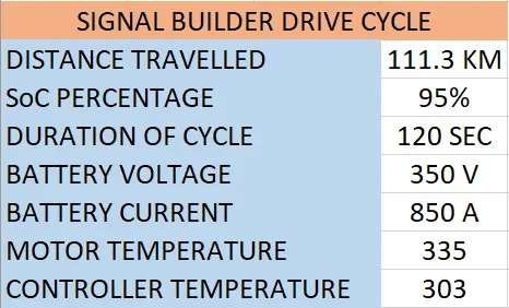
By using the Custom drive cycle(signal builder), The distance travelled by the vehicle is 111.3 kms. Both the fedback velocity and drive cycle pattern are matching with each other at 12.5m/s. At the battery SoC is also observed and conclude that the left over charge in the battery is almost 95% percentage and exhausted 5% of charge to travel upto 110 seconds of cycle duration. The battery voltage has touched the peak of 350v of battery voltage measurment and current of 850 amps is the highest peak value of current measure. when it comes to energy consumption is almost 510 watts. The temperature of the motor has reached to 335 and motor controller temp is 303. Hence the vehicle is been travelled for 100km at 45kmph which is converted to m/s which gives 12.5m/s which can be observed in the plot and total duration in this drive cycle is 110 seconds in that 10 seconds are assigned to start thevehicle and then run at constant speed of 12.5m/s which is 45kmph for 100 seconds.
Thank you