Week-7 Challenge: DC Motor Control
1. A. Explain a MATLAB demo model named ‘Speed control of a DC motor using BJT H-bridge’.
Answer:
Introduction
BJT(Bi-polar transistor):
Bi-polar transistor is widely known as BJT. It has three terminals namely base, collector, emitter. The major use of this transistor is to amplify current. These are useful at switches or amplifiers. They have a wide application in electronic devices like mobile phones, televisions, radio transmitters, and industrial control. This BJT operates in three region.
Active region: In this mode the transistor works like an amplifier.
Saturation region: In this mode the transistor works likes a switch where Icoll = Isat. Icoll means collector current and I sat means saturation current.
Cut-off region: In this mode the transistor will be in off mode where Icoll = 0
H-bridge:
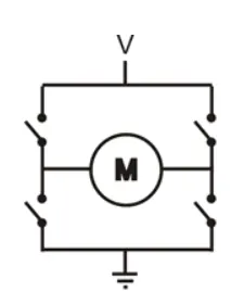
H-bridge circuit consists of power converter to control the motor's speed. BAsically it swaps the polarites of applied voltage. WHile changing the polarties of the motor's applied voltage, can change the direction of the motor's rotation. H-bridge operates in two modes which are shown below. So swapping from one stage to other stage the motor input voltage is also changed.
H-bridge construction which respective to motor and power electronic switches:
Operation:
The H-bridge arrangement is generally used to reverse the polarity/direction of the motor, but can also be used to 'brake' the motor, where the motor comes to a sudden stop, as the motor's terminals are shorted.
These are two stages where the H-bridge works on:
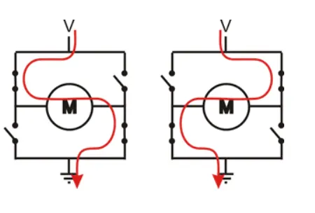
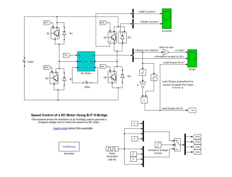
1st stage: When the input supply is given to converter circuit to control the motor. Only two diagonal switches(BJTs) are conducted while other diagonal switches(BJTs) are kept in open switching mode as shown. While this process continues the motor's direction will be in clockwise direction.
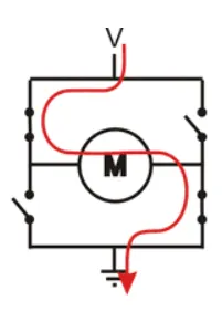
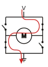
2nd stage: When the input supply is given to converter circuit to control the motor's other CCW(counter-clock wise). Only two diagonal switches(BJTs) are conducted while other diagonal switches are kept in open switching mode as shown. While this process continues the motor's direction will be in counter-clockwise direction.
Simulink model circuit of speed control of DC motor using BJT H-bridge:
Simulink model outputs of speed of the motor, Armature current, torque of load:
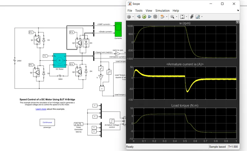
1B. Comment on the armature current shoot-up from the scope results.
Output of H-bridge circuit shows the Armature current of motor:
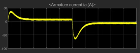
Above screen shot of the output of H-bridge circuit shows the Armature current of motor. On the armature current there is a rise in plot initially. these cuurents are called as "INRUSH CURRENTS", these are caused or appeared at initial stage of starting of DC motor. Due to DC motor resistance of rotor coil winding is lesser, thus the initial currents drwan by the motor at start of motor will be of higher amperes and it is given by
I = V/R
I = 220/1Ω(resistance value is taken for reference purpose only)
I = 220amps
Resistance value is taken for reference purpose only, in practical senerio it will be lesser. So when 220 amps is drawn from the source input then the rotor windings can burnout completely.
Remedy in practical senerio: To get rid of this in rush currents, we generally use stators for DC motor like 3-point starters, 5-point stators.
Remedy in simulink model: To get rid of shoot-up currents we need to change(reduce) the duty cycle to make the armature cuurents shoot-ups to decrease.
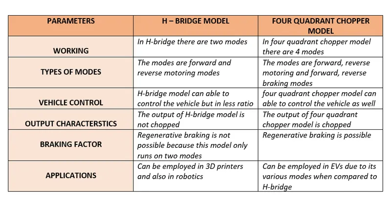
1C. Refer to the help section of ‘The Four-Quadrant Chopper DC Drive (DC7) block’. Compare it with the H-bridge model.
Simulink model circuit of speed control of DC motor using BJT H-bridge:
Simulink model of The Four-Quadrant Chopper DC Drive (DC7) block:
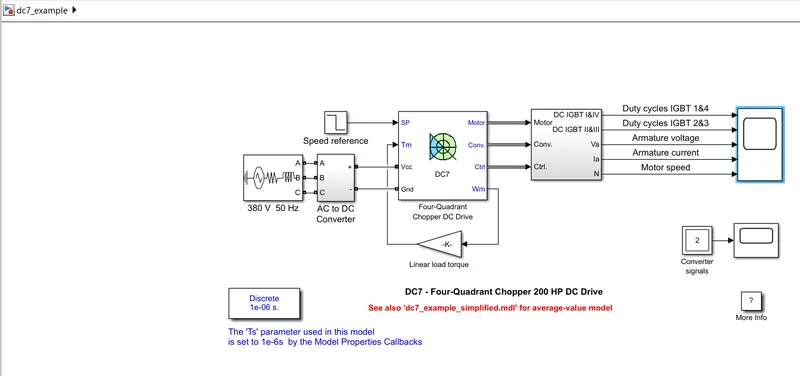
Comparsion of H-bridge model and four quadrant chopper model:
Question 2:
Develop a 2-quadrant chopper using simulink & explain the working of the same with the relevant results.
Two-quadrant chopper simulink model:
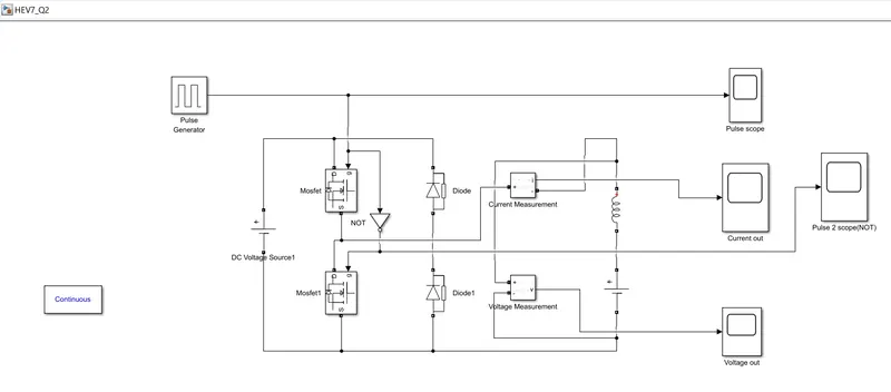
where DC source is set to 12v and Back emf is set to 6v and inductor is set to 0.001 andpulse generator is attached below.
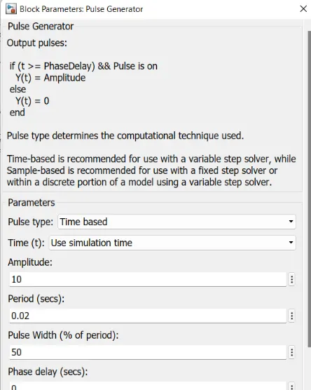
Pulse generator parameters setting:
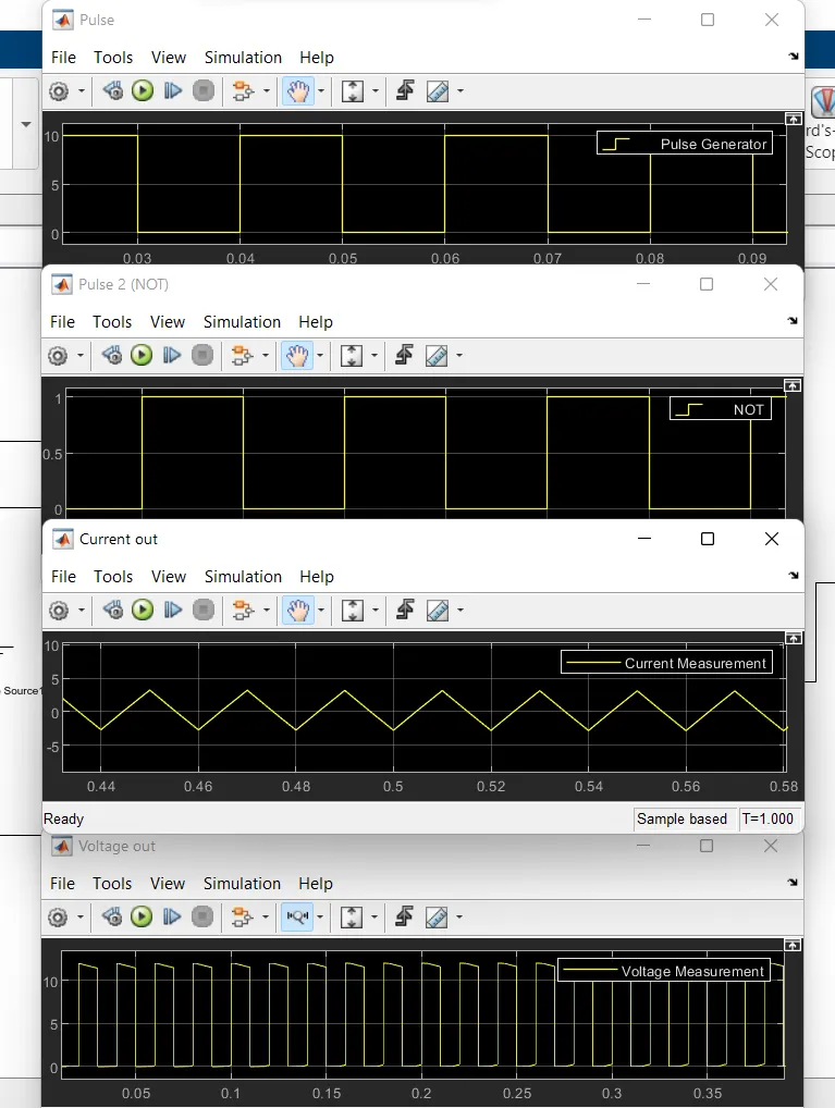
Two-quadrant chopper simulink model output plots of pulse input, current and voltage measurments:
Working of the model:
Two-quadrant chopper basic circuit through which the simulink model is been designed and desired output plots are obtained.
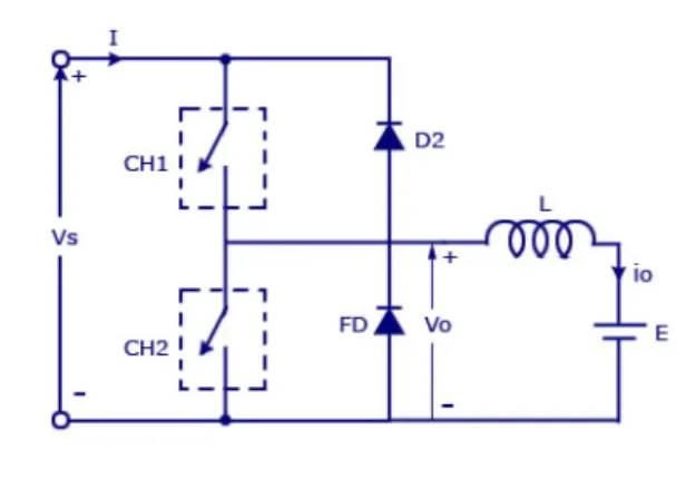
- In second quadrant there are only two converter and those converter can be MOSFETs and IGBTs.
- THen these converter starts there conduction only when the input "GATE PULSE" is applied to them. After applying the gate pulse to respective converters.
- The CH2 converter(switch) operates while keeping the remaining switches OFF.
- When CH2 switch is in conducting mode, CH1 switch is in non conducting mode. While keeping this point in mind, the NOT gate is employed to supply the pulse opposite to pulse given to other converter.
- When the chopper is ON then the freewheeling diode starts conducting and the output voltage Vo will be equal to Vs.
- The direction of the load current Io will be reversed. The current Io will flowing towards the source and it will be positive.
- The output of the "voltage" plot is in positive half cycle and where as "current" plot in positive and negative half cycle, therefore the voltage is positive and current is positive and negative.
- Thus we conclude that the second quadrant model operates as a "step-up chopper" .
Question3:
Explain in a brief about operation of BLDC motor
Operation of BLDC motor
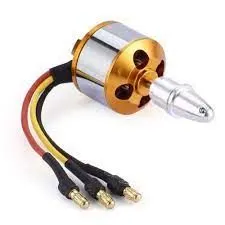
- BLDC motor is called as brushless DC electric motor and also known as permanent magnet synchromous motor(PMSM). Which requires and runs on DC supply.
- Construction: BLDC motor has rotor and stator. The rotor is the rotating part and has permanent magnets which moves the electromagnets to the stator. Whereas stator is the stationary part and contains stator windings.
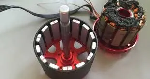
- THere are basically three windings which are electrically placed 120degrees apart.
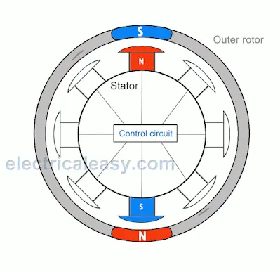
- Permanent magnets on the rotor aligns with the electromagnets of the stator, and as soon as it aligns, the next electromagnets are energized. Thus, the rotor keeps running.
- Below animated image shows the water clear opeartion of BLDC motor where rotor and stator in phases of energizing the poles.
Applications of BLDC motors:
- When it comes to BLDC motors applications the first in the list would be EVs application. In EVs it is widely used as "HUB motor" which is embedded in the wheel of the vehicle itself.
- Now-a-days BLDC fans are widely seeing profits due to the power saving factor.
- It would also be employed in robotics as well.
- It is widely employed in Drone technology because of it lesser weight and less power consumption also.
Advantages of BLDC motors:
- BLDC motors are Lesser weight and consumes less power also.
- BLDC motors have high level of control over the position and speed
- Brushless DC motor provides high torque also.
- There is no point of commutation because of absence of brushes , as the name suggests the Brushless motor.
** BLDC motor doesn't run without controller?
Yes, BLDC motor doesnot run without controller. Here controller used to detect the postion of the rotor inside the motor. The data from the sensors gives it to controller and thus controls the input supply to winding of the stator.
BELOW IMAGE IS THE CONTROLLER OF BLDC MOTOR USED IN EVs

List of the sensors used:
- Hall effect sensors is mostly used controller unit in BLDC motor
- optical sensors
- rotary sensors
- variable reluctance sensors