Week-11 Challenge: Braking
Question1:
For a defined driving cycle, calculate the energy required for braking
Solution:
Here I had to consider the Indian drive cycle(IDC) drive cycle
Introduction of IDC drive cycle:
Firstly, IDC means Indian drive cycle where this drive cycle resembles the Indian road driving scenarios. The IDC cycle image tells more about what is IDC cycle.
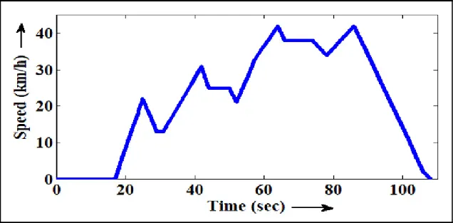
The above IDC cycle describes the real Indian road driving conditions. In our great country India, the majority are 2W comparatively. Indian vehicles are driven at low speeds, and low acceleration due to city conditions. So based on this scenario the Indian driving cycle is formulated after collecting real-world data from major cities representing actual driving patterns.
Total braking energy = E = (1/2)*mass of the vehicle(Initial speed - Final speed)^2
Here the mass of the vehicle is taken by consideration of ATHER 450 2W vehicle, where the kerb(curb) weight of the vehicle is 111.6kgs.

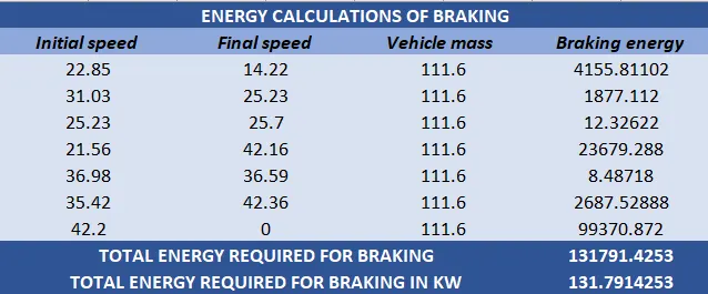
The above image shows the excel data of the Indian drive cycle(IDC). As discussed above vehicle mass is 111.6 kg kerb weight of the ATHER 450 vehicle. Based on the IDC cycle the initial speed and final speed are obtained. The total energy required for braking's formula is considered to calculate the total energy.
Conclusion: Total energy required for braking in KW = 131.79KW
Question 2:
Why electric motor can’t develop braking torque at high speed similar to starting? How electric and mechanical brakes are coordinated?
Answer:
Electric motors can’t develop braking torque at a high speed similar to starting, because Braking torque is applied in the opposite direction of the rotation. We can use a mechanical brake to produce braking torque.
Here we need to grasp one of the types of braking called "Regenerative braking" where this kind of braking is all about generating supply by converting the kinetic energy. This kind of braking only happens when the speed of the motor exceeds the synchronous speed. Then the motor can act as a generator and it can supply voltage to the load. In electrical terminology, the torque direction and as well as current direction changes, and then the braking happens.
Image showing the torque-speed cahracterstics of 3 modes of motor includes regenerative braking
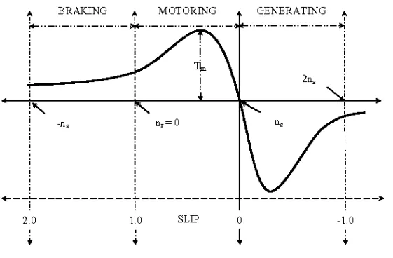
We know about acceleration and deceleration of motors. In which the maximum torque of both acceleration and deceleration of motor are not equal.
Image showing acceleration and deceleration of motor with respective torque and speed
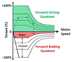
We also know that the speed is inversly propotional to torque of motor. So when the motor is opearted at higher speed the torque constant also acts accordingly.
So the reason behind the Electric motors can’t develop braking torque at a high speed similar to starting is cleared.
How electric and mechanical brakes are coordinated?
Answer:
For better understanding of the coordinated between electric and mechanical brakes we need to know the aspect of "Total brake distribution". This Total brake distribution has identifed as electrical brake and mechanical brakes. This both electrical and mechanical brakes are co-ordinated and alligned and combinely opearted. This control strategies are known as "Brake control strategies", which are discussed in follwing
Series braking : In series braking both the electrical and mechanical brakes are co-ordinated and applied respectively(one by one). Like, either mechanical brake or electrical brake are applied at once.
Parallel braking : In Parallel braking both the electrical and mechanical brakes are co-ordinated and can be applied simultaneously(both at time).
e
Question 3:
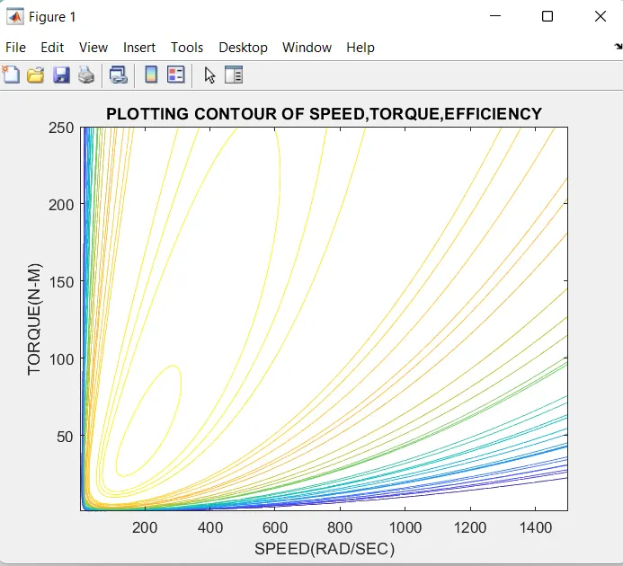
Make a MATLAB program which plots contour of given motor speed, torque and efficiency values. Attach the code as a .m file attach a screenshot of all the plots
Solution:
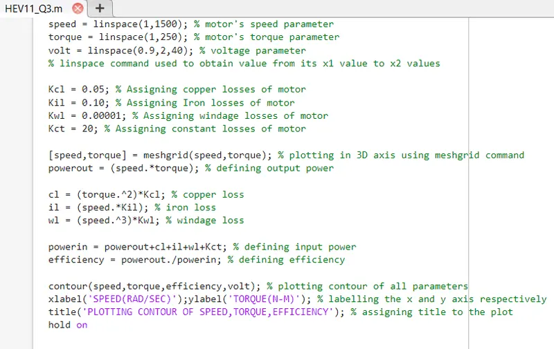
Matlab code for plotting contour of motor's speed, torque, efficiency parameters:
Output plot for contour of motor speed, torque and efficiency parameters: