Week-6 Challenge: EV Drivetrain
Question 1:
Which types of power converter circuits are employed in electric and hybrid electric vehicle?
Power converter circuits: These are the circuit which are used to convert from state of source to other state of source. These state of source can be either AC state or DC state. According to requirement these converters are employed. Below there are some converters which are employed in both Hybrid electric vehicle and Electric vehicle.
o Rectifier
o DC to DC converter
o Inverter
o Variable frequency drive
Rectifier:
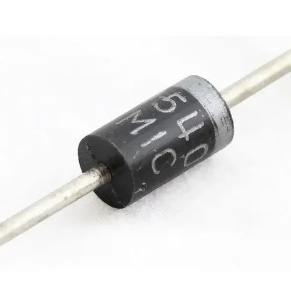
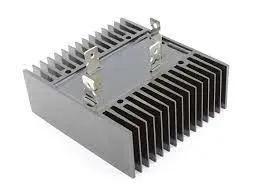
These are converter which are used to convert AC supply to DC supply. After conversion there might be employment of filters to further filter out the ripples and unwanted frequencies. For smaller ranges of voltage, current they will use diodes. In case of larger range, SCRs are employed which does the same task.
Applications: Electrical vehicles to supply battery charging from EVSE, Used at LED lights, transmission(HVDC) systems.
DC to DC converter:
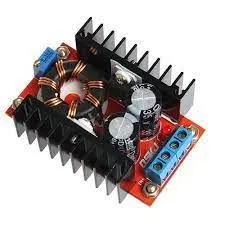
These are power converter which are also called "CHOPPER". Basically, these converters convert from one voltage level to another voltage level generally from DC to DC so these are called as DC to DC converters. As name suggest us chopper means chopping the output signal so that conversion takes place.
Applications: EVSE(electrical vehicle supply equipment), speed controller of motors.
Inverter:
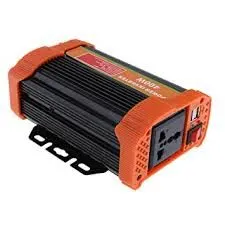
This is a power converter and one of the most important power converter in the industry because of its applications. The power electronics device Inverter which used to convert DC to AC supply. In general it can also convert DC battery source to Alternating supply.
Applications: In EVs these are used to convert DC battery source to AC supply to supply it to AC motor, Home appliances, HVDC transmission system, Cars.
Variable frequency drive(VFD):
These VFDs are power converters which are used to control the motor by varying the given input frquency and also voltage and controls the connected motors. Generally these VFDs are used to control the speed of motors like BLDC, induction motors, etc while controlling frequency quantity.
Applications: IN EVs to control motor speed, compressors of refridgerators and ACs.
Question2:
Motor and Controller Parameters:
Rated Armature voltage= 72 V
Rated armature current= 400 A
Ra= 0.5Ω, KΦ= 0.7 Volt second
Chopper Switching frequency= 400 Hz
The vehicle speed-torque characteristics are given by the below equation

What is EV steady state speed if duty cycle is 70%?
Solution:
Given data
Battery pack or Armature voltage (Va) = 72V
Rated Armature current (Ia) = 400A
Armature resistance (Ra) = 0.5Ω
Torque constant (KΦ) = 0.7 volt second
Chopper Switching frequency = 400 Hz
we know that
w = [(V/KΦ)-(Ra/KΦ^2)] x Tm ----------->equation(1)
where w is the angular speed/velocity of DC motor
Tm is the torque of the motor
After rearranging the values to obtain "T" from equation 1, we get
Tm = ((V x KΦ)/Ra) - (w x KΦ^2)/Ra)) ----------->equation(2)
Now subsitute the above values in equation(2), we get
Tm = ((72V x 0.7)/0.5Ω) - (w x 0.7^2)/0.5Ω))
Tm = 70.56 - 0.98w
given that torque of vehicle is
given that to calculate the steady state speed , it means Tv = Tm condition so
V = ?
since duty cycle is 70%, then Voltage is given as
72v x (70/100) = 50.4V
V = 50.4V
- Tv = 24.7 + 0.0051w^2;
- Tm = (VxKpi)/Ra - (w x Kpi^2)/Ra
- Tm = ( 50.5 x 0.7)/0.5 - (w x 0.49)/0.5
- Tm = 70.56 - 0.98w
- Tv = Tm
- 24.7 + 0.0051w^2 = 70.56 - 0.98w
- 70.56 - 0.98 w = 24.7 + 0.0051w^2
- 70.56 - 24.7 = 0.0051w^2 + 0.98w
- 45.86 = w(0.0051w + 0.98)
- w(0.0051w + 0.98) = 45.86
- w = 45.86/(0.0051w + 0.98)
- w = 38.914 rad/s or w = -231.071
since speed of the vehicle will not be in negative values, we will consider positive value, so EV steady state speed is 38.914 rad/s
Question 3:
Develop a mathematical model of a DC Motor for the below equation using Simulink.
ω= (V/Kϕ -Ra/Kϕ^2 )*T
Solution:
Taking values of parameters in the below order. After substituting the values in "W" we get the following
w = (V/KΦ)-(Ra/KΦ^2) x T
w = (200/3)-(2/3^2) x 10
w = 664.44rad/sec
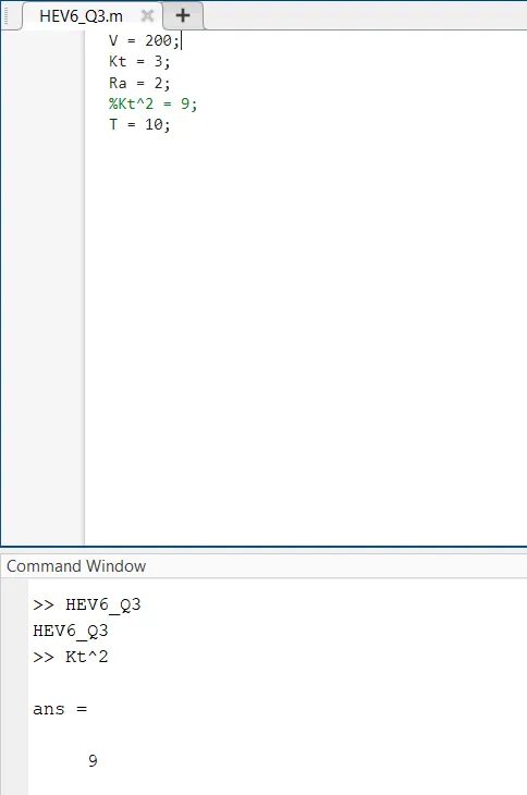
Matlab code with comments
V = 200; % input voltage of the system
Kt = 3; % torque constant(K tita is named as Kt)
Ra = 2; % armature resistance
T = 10; % torque of motor
% "w" is the angular speed of the motor
% w = (V/KΦ)-(Ra/KΦ^2) x T
Simulink model with display block attached shows the solution of W in rad/sec -
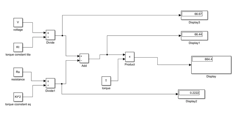
CONCLUSION: So in general mathematical calculation we got W = 664.444 rad/sec and by using simulink model connections we got the same value as 666.4rad/sec.
Question4:
Induction Versus DC brushless motors by Wally Rippel, Tesla
Brief summary about author’s perspective -
One Size Does Not Fit All
- In this unpleasent world which is filled up with combustion engines is causing damage to environment. After some competition and dominance thereafter only one engine would in market and would be in production.
- likewise in Electrical vehicle lead acid batteries are replaced by lithuim ion batteries and while it comes to motors, DC brushless and induction motors does
- A Closer Look
- While it comes to DC brushless motors(drives). the rotor includes two or more permanent magnets that generate a DC magnetic field .
- This permanent magnets's magnetic field enters the stator core and interacts with currents flowing within the windings to produce a torque.
- As the rotor rotates, the magnitude and polarity of the stator currents be continuously varied such that the torque remains constant.
- The electromechanical conversion optimally efficient. Without inverters, brushless motors are useless motors.
- Author moves the topic to induction motor which was invented by Tesla.
- He says about the construction of induction motors while differentiating DC brushless motors.
- After describing the induction motor's working theme, he comes over the 3phase indction motors those who runs on 3phase power.
- He also says that the fact that induction motors are directly runs on utility power is the main reason for their success.
- The important considerations is Induction motors which are constant speed machines, needs AC supply and deosnot runs on DC.
- To make them run on DC supply and compete with BLDC motors, one must need inverter, so that the conversion of DC to AC done
- Brushless or Induction?
- In 1990s EVs are'nt much powered by DC brushless drives. But Hybrids are powered by DC brushless motors.
- There are major similarities between them, the only difference them are rotors and inverter circuits.
- He also talks about the heating effects in both motors and BLDC motors can be operate on unity power factor also.
- Wally rippel stated about their extra circuitary, losses, and also about torques also.
- Wally also says that permanent magnets are Extremely durable magnets and costly. Extremely durable magnet (PM) rotors are likewise challenging to deal with because of exceptionally huge powers.
- This implies that enlistment engines will probably hold an expense advantage over PM machines and they are simpler to secure.
- He forgot to say at last that "Induction machines are more difficult to control". Because of their complexity.
- Achieving stability over the entire torque-speed range and over temperature is more difficult with induction than with DC brushless.Still No Winner
- Wally concludes that the BLDC motors will dominate the Hybrid and plugin Hybrid vehicles
- ANd induction motors will rule the pure electric vehicles due to their higher performance rate.
- He also raises a question that, what happens hybrid vehicles rule the industry when their performance increases.
- At last, both motor drives has a ability to rule the industry of hybrid and electric vehicles.