Project 2 - Modeling of 3 phase Induction Motor Drive
- Model 3 Phase Inverter using Simulink (model the parasitic as well) with a switching frequency of 10Khz using 3 phase Squirrel Cage Induction motor, using V/F method, open loop
Design Parameters:
- Power = 100 HP
- DC Voltage = 800 V
- Output Voltage = 460 VRMS – line to line
- Initial Speed = 1500 RPM
- Final Speed = 1000 RPM
- Initial Load Torque = 10 Nm
- Final Torque=20 Nm
- Torque Step Time = 0.1 secs
For Induction Motor model – use Asynchronous Machine from Simulink with Squirrel Cage Preset Model – 05 , for 100HP Motor
For back emf to speed relation, assume a linear rate from 0.25 to 1, with speed changing from 500 RPM to 2000 RPM
Plot speed, stator voltage (line to line) and frequency.
Plot stator line voltage, phase current
1. INTRODUCTION
Three-phase inverter:
The Three-phase inverter is used to change the DC voltage to three-phase AC supply. Generally, these are used in high power and variable frequency drive applications. Generally, the three arms of this inverter
will be delayed with 120 degrees angle to generate a 3 phase AC supply. The switches used in the inverter have 50% of ratio and switching can be occurred after every 60 degrees angle. The switches like S1, S2,
S3, S4, S5, and S6 will complement each other. In this, three inverters with single-phase are placed across a similar DC source. The pole voltages within the three-phase inverter are equivalent to the pole
voltages within the half-bridge inverter with a single phase. This three phase inverter is a power electronics device which converts DC signal to particular AC signal as the output.
V/F control method:
This V/F is a type of control method for the induction method where it is implemented usually for the induction motor. The Synchronous speed can be controlled by varying the supply frequency. Voltage induced
in the stator is 𝐸1 ∝ Ф𝑓where Ф is the air-gap flux and f is the supply frequency. As we can neglect the stator voltage drop we obtain terminal voltage 𝑉1 ∝ Ф𝑓. Thus reducing the frequency without changing the
supply voltage will lead to an increase in the air-gap flux which is undesirable. Hence whenever frequency is varied in order to control speed, the terminal voltage is also varied so as to maintain the V/f ratio
constant. Thus by maintaining a constant V/f ratio, the maximum torque of the motor becomes constant for changing speed. When V/f Control is implemented, for various frequencies inside the operating region,
the maximum torque remains the same as the speed varies. Thus maintaining the V/f ratio constant helps us to maintain a constant maximum torque while controlling the speed as per our requirement.
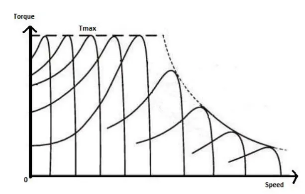
fig(a) Torque-Speed characteristics for V/f Controlled Induction Motor
3-Phase squirrel cage Induction motor:
Squirrel induction motor working is based on the principle of electromagnetism. When the stator winding is supplied with a three-phase AC, it produces a rotating magnetic field (RMF) which has a speed called
synchronous speed. This RMF causes voltage induced in the rotor bars. So, that short-circuit current flows through that. Due to these rotor currents, a self magnetic field is generated which interacts with the
stator field. Now, as per the principle, the rotor field starts opposing its cause. when the RMF catches the rotor moment, the rotor current drops to zero. Then there would be no relative moment between the rotor
and RMF. The zero tangential force is experienced by the rotor and reduces for a moment. After this reduction in the moment of the rotor, the rotor current is induced again by the reconstruction of relative motion
between the RMF and the rotor. Hence the tangential force of the rotor for the rotation is restored and starts by following the RMF. In this case, the rotor maintains a constant speed, which is less than the speed
of RMF and synchronous speed. Here, the difference between the speed of RMF and the rotor is measured in the form of slip. The final frequency of the rotor can be obtained by the multiplication of slip and
supply frequency.
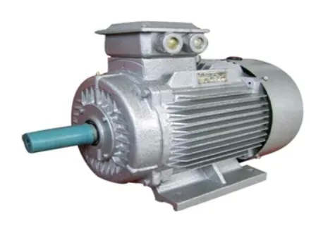
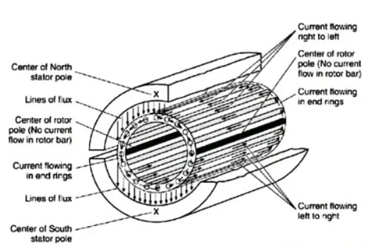
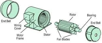
Fig(b) 3-Phase squirrel cage induction motor and its parts
2. SIMULINK MODEL SUBSYSTEMS
V/F control subsystem
The V/F subsystem would consists of motor speed controlling system where it would control the gate triggering in order to obtain the required running speed of induction motor. As shown below for this controller
we are converting the reference speed to Frequency.
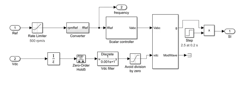
The reference Speed will getting from the Rate Limitor block with (500 to -1500 rpm) limits and this will be devided with the 1 over frequency followed by poles gain blocks and dc voltage reference is also feed to
the PWM three phase generator. This will create the gate pulses as per the controlling of frequency method. After getting the pulses from the V/F controller then the Inverter start the working . The output supply
(3phase ) will be connected to the Asynchronous Machine(SI Units) block with using the RC filter block.
3-Phase Inverter
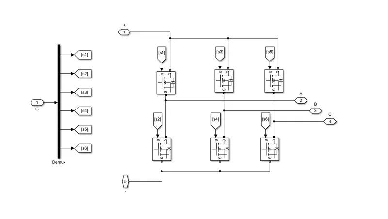
The controlling of 3 phase squirrel cage Induction motor by using the V/F method with 3phase Inverter by using the following steps. Firstly we are created the 3 phase inverter by using the "MOSFET" as power
switching device. The below three phase inverter is MOSFET based inverter. Each mosfet is been powered with gate triggering from the above susbystem, in order to controll the speed of the induction motor as
required. This three phase inverter is basically a power electronics device which is converts the DC supply to required AC supply. In order to power the AC induction motor. This 3 phase inverter can be employed
in many applications like Eleectrical vehicles, power transmission (HVDC), etc. systems. So here this 3phase inverter will consists a three legs with 2 numbers of Power switch (MOSFET) for each leg. These 6
Power switch (MOSFET) will operate both high(positive signal) and low(negative) Signal operation. The gate pulses are getting from the V/F Controller Method Subsystem.
3. SIMULINK MODEL IMPORTANT BLOCKS
Asynchoronus Motor
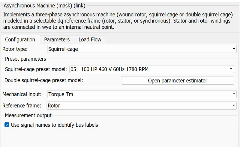
Fig(a) Induction motor parameters
The Induction motor described above is the three phase induction motor. The squirrel cage three phase induction motor have the following data input parameters.
Voltage rating of induction motor = 460V
Input Frequency of induction motor = 60Hz
Rated speed of the induction motor = 1780RPM
Capacity of the motor = 100HP
Step Input
This Step Input is utilised as the reference speed in order to control the induction motor and to obtain the required 1000 rpm speed at the final speed. As the induction motor would operate at 1500 rpm and we
required the motor to run at 1000 rpm after a time period from the initial speed. As the image below has the data values of the step time which is used as the refernece speed of the motor. The sample time is
considered as Tsc. Which means it is the control sample time of the induction motor. The Tsc is equal to 1/(Fsw*10) where Fsw is the switching frequnecy of the input.
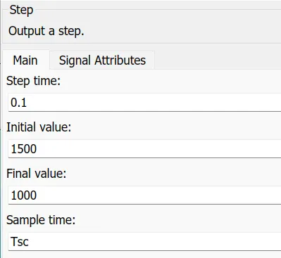
Fig(b) Step Input for reference speed of the motor input parameters
DC Source Input
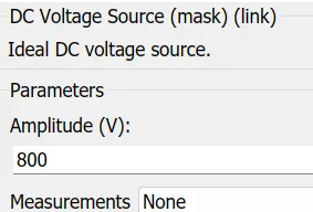
The DC source input is the input source which is given as input signal to the 3 phase inverter in order to power the motor by means of MOSFETs devices.
4. SIMULINK MODEL
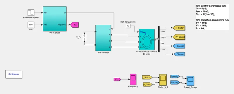
FIG(a) Simulink model for speed control of induction motor with V/F method
o The above simulink model is the model for three phase inverter which is used to operate the three phase induction motor. where the Induction Motor model is Asynchronous Machine with Squirrel Cage Preset
Model – 05 , for 100HP Motor parameters.
o The Three-phase inverter is used to change the DC voltage to three-phase AC supply. The switches like S1, S2, S3, S4, S5, and S6 will complement each other. In this, three inverters with single-phase are \
placed across a similar DC source. The pole voltages within the three-phase inverter are equivalent to the pole voltages within the half-bridge inverter with a single phase.
o This V/F is a type of control method for the induction method. When V/f Control is implemented, for various frequencies inside the operating region, the maximum torque remains the same as the speed
varies. Thus maintaining the V/f ratio constant helps us to maintain a constant maximum torque while controlling the speed as per our requirement.
5. SIMULINK MODEL OUTPUTS
Stator parameter output
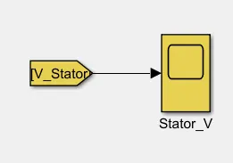
fig(a) Scope with voltage stator parameters
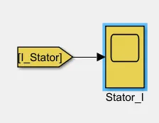
fig(b) Scope with current stator parameters
Stator voltage with transients as there is no filters attached
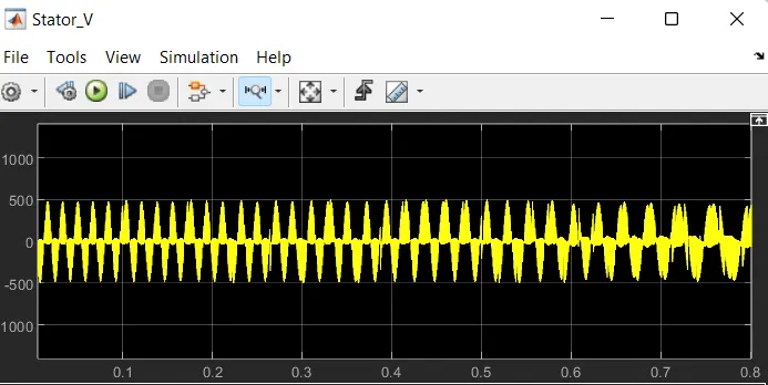
fig(a) Stator voltage of motor
Stator current with transients as there is no filters attached and draws more initial in-rush currents
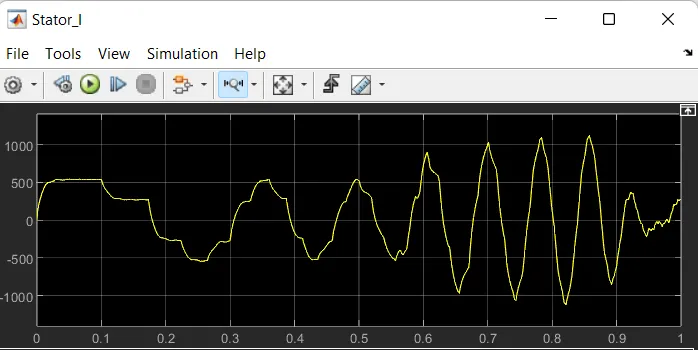
fig(b) Stator current of motor
Frequency control of Induction motor
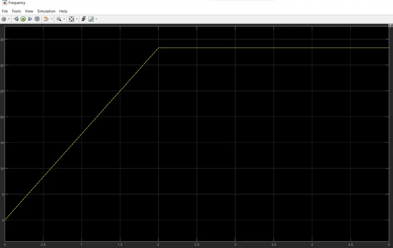
The above scope is the frequency scope of the induction motor where the frequency output has minimum and maximum frequency values, which are discussed below.
Minimum frequency = 0Hz at initially
Maximum frequency = 33Hz(appox) at 2 seconds
Speed and Torque of induction motor
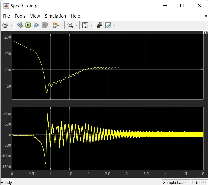
The Speed and Torque of the Induction Motor are plotted above. The top plot is for the Speed of the Motor. The speed plot has been settled after 3 seconds of time period. The Bottom plot will be the Torque of the
Motor. where the torque of the induction motor is also been plotted and the torque has been oscillated initially and finally the torque of the motor also settled after 3 seonds of time period. As the speed of the
induction motor has been reduced from 1500 rpm to 1000rpm at running.
6. CONCLUSION
Hence the Controlling of 3phase induction motor using the Method of V/F which is voltage and frequency method has been adapted and been implemented on the three phase induction motor and the 3phase
inverter would achieved properly. The speed of the induction motor has been reduced from 1500 rpm to 1000rpm at running. The speed control is implemented with V/F control method.
Queestion 2:
2. Use the 3 phase inductor motor theory to derive the transfer function of 3 phase Induction Motor
1. INTRODUCTION
3 phase Induction motor:
A 3-phase induction motor consists of a stator and a rotor. The stator carries a 3-phase stator winding while the rotor carries a short-circuited winding called rotor winding. The stator winding is supplied from a 3-
phase supply. The rotor winding drives its voltage and power from the stator winding through electromagnetic induction.
Fig(a) Three phase induction motor
2. TRANSFER FUNCTION OF INDUCTION MOTOR
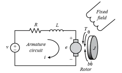
Applying KVL then , we get
V - IaRa - IaLa - e = 0 -------------> (1)
T tita = K(t) Ia - Ia = T tita/Kt
Vb = Kb . B tita - Vb
Vb = Kb . B tita
Applying laplace transform
e - Ra(Tm/Kt) - La S(Tm/Kt) - KbS . B tita = 0
e - Tm[(Ra + LaS)/Kt] - KbS B tita = 0
T tita - D b tita = Jb tita
T tita = b tita (Js^2 + Ds)
e = b tita(Js^2 + Ds) [(Ra + LaS)/Kt] - KbS . b tita = 0
e = b tita[(Js^2 + Ds).(Ra+La) / (Kt) ) + Kbs]
eKt = btita [(Js^2 + Ds) (Ra + La) + Kb Kt - s]
Kt/(Js^2+Ds)(Rs+Las) + KbKtS = B tita/e
Wm = B tita = D tita.m/dt
Wm = B tita S
Transfer fuction of induction motor is given as in the following
Wm/e = (Kt s) / (Js^2+Ds)(Ra+Las)+KbKTS
Wm/e = (Kt s) / (Js^2+Ds)(Ra+Las)+KbKTS =====> Transfer function of Induction motor
3. CONCLUSION
Hence the Transfer Function for Induction Motor is given as followes
Wm / e =KtS / (JS²+DS) (Ra+LaS)+KbKtS
The Transfer Function For the three Phase Induction Motor is determined.
3. Model 3 phase induction motor with a 3 phase inverter using Direct Torque control using an Average Model, Implement both torque and flux control to achieve desired power.
Design Parameters:
- Initial Speed = 0 RPM
- Flux Target = 2.5 webers
- DC Voltage = 500 V;
- Fundamental Frequency = 60 Hz
- Speed Step Time = 0.01 secs
- Determine fundamental speed based upon fundamental frequency
- Determine the switching sequence for direct torque control
- Moment of Inertia = 0.1 Kgm^2
- Load Torque Initial = 0 Nm
- Final Load Torque = 50 Nm
- Torque Step Time = 0.03 secs
Motor Parameters: (Create an Average Model)
- Stator Resistance = 0.5 Ohms
- Rotor Resistance = 0.2 Ohms
- Stator Leakage Inductance = 20 mH
- Rotor Leakage Inductance = 10 mH
- Magnetizing Inductance = 200 mH
- Number of Poles = 4
- Torque to Speed
1. INTRODUCTION
Direct torque control
The direct torque control method is similar to FOC control method. The direct torque control (DTC) controls motor torque directly, without a modulator, so torque response is much faster. The Direct torque
control (DTC) is a technique that allows you to instantaneously control the motor magnetic flux and its electromagnetic torque in a decoupled way. Controlling the torque directly permits accurate static and
dynamic speed regulation. Direct torque control (DTC) circuits are less complicated than FOC circuits since they do not require the usage of a PWM inverter, a speed sensor, or reference frame transformers.
Because information regarding the exact position of the rotor is not necessary in such systems.
2. STRATEGY USED TO DETERMINE VOLTAGE VECTOR
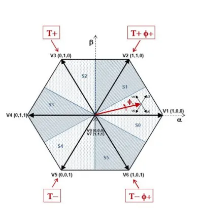
fig(a) Voltage vector with respective to torque and flux
The figure above illustrates the strategy used to determine the best voltage vector when the flux linkage is located in sector 0. The above image describes about the voltage vector with respective to the torque
and flux. It has some cases in which the strategy is used to determine the best voltage vector with respect to flux linkages.
-
When the torque should be increased and the flux should stay unchanged then V3 is selected . Selecting the V3 voltage vector speeds up the flux and thus applies an acceleration torque to the rotor while slightly decreasing the flux magnitude.
-
When the torque should be increased and the flux should be increased then V2 is selected . Selecting the V2 voltage vector slightly speeds up the flux and increases its magnitude.
-
When the torque should be reduced and the flux should be increased then V6 is selected . Selecting the V6 voltage vector slows down the flux and thus applies a deceleration torque to the rotor while increasing the flux magnitude.
-
When the torque should be reduced and the flux should stay unchanged then V5 is selected . Selecting V5 the voltage vector applies a deceleration torque to the rotor and slightly decreases the flux magnitude. Note that voltage vectors V1 and V4 are not selected in sector 0. Using these two vectors would have too much negative impact on the desired flux value. Finally, to keep the torque and the flux unchanged, the null voltage vectors V0 or V7 are selected.
When the flux linkage vector moves to sector 1, the selected voltage vectors become V4 for case 1, V3 for case 2, V1 for case 3, and V6 for case 4, and vectors V2 and V5 are not used. This 60 degree shift in the
voltage vectors happens each time the flux linkage vector enters a new sector. In this way the flux linkages vector moving can selected voltage vectors can change. It means there is shift in their vector when the
flux linkages are changing.
3. SIMULINK MODEL
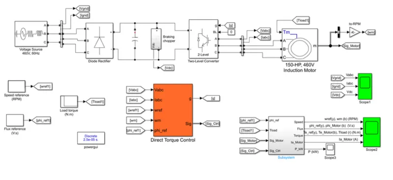
fig(b) SImulink model for direct torque control of Induction motor
The three phase induction motor is controlled By using the direct Torque method is as followes . firstly we took the Supply source ab=nd sentd to the DClink capacitor by using the universal bridge block works as
Diode rectifier. After that te supply from the Dc link is fed to the Two level converter block. from this inverter Synchronous machine .the motor is working Based on the commands from the Converter Signal block.
4. DESIGN PARAMETERES
Input Voltage Source Block with 460V and 60Hz
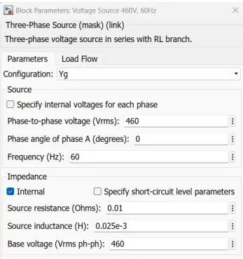
fig(a) INput voltage source
Universal Bridge Parameters with 3 arms bridge circuit block used as rectifier
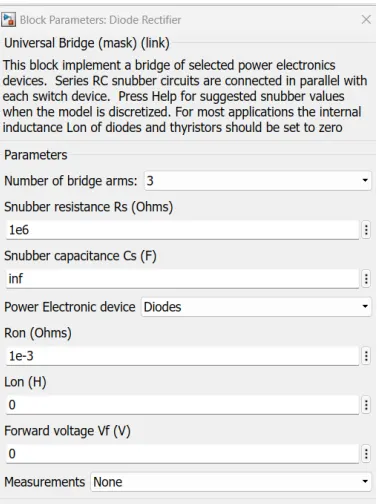
fig(b) 3 arms bridge rectifer circuit
Two level Inverter Block used as INverter where it inverts DC to AC supply
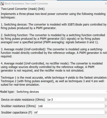
fig(c) Two level inverter block
Asynchronous Machine which is Induction motor
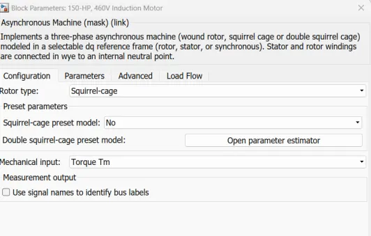
fig(d) Induction motor wth 150HP and 460V electrical parameters
The Inverter will works the Signals commands what we generated by using the Direct Torque method. Direct torque control (DTC) is a technique that allows you to instantaneously control the motor magnetic flux
and its electromagnetic torque in a decoupled way. Controlling the torque directly permits accurate static and dynamic speed regulation. The electrical energy is supplied by a three-phase AC/DC diode rectifier
connected to a 460 V, 60 Hz grid equivalent. The DC bus is connected to a three-phase, two-level converter.
This converter generates the variable voltage and frequency required for variable-speed operation of the 150 HP induction motor. In addition, a braking chopper is connected to the DC bus in order to dissipate the
kinetic energy of the motor during deceleration. An inverter-fed induction motor drive can be controlled through various techniques depending on application, desired performance, and controller design
complexity. Commonly used schemes are scalar control (V/Hz control or open loop flux control) or vector control (field-oriented control or direct torque control). This example uses a hysteresis-based direct torque
control (DTC) technique.
5. SIMULINK MODEL SUBSYSTEMS
Flux and Torque Calculation
The stator flux linkage is estimated by integrating the stator voltages, and torque is calculated based on the estimated flux and the motor currents. This Flux and Torque calculation is desin by using the abc to
Alpha-Beta-Zero block are send to the transfer function block. From this two abc to Alpha-Beta-Zero blocks we are created the three output signals ,Those are Phase magnitude phase angle and torques output.
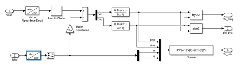
fig(a) Flux and torque calculation subsystem
Speed Regulator
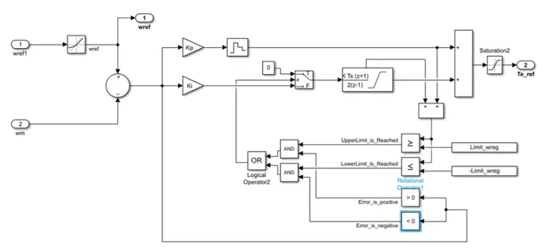
The regulator compares the actual motor speed with the speed reference and generates the torque reference. This block implements a speed regulator using an ant-windup PI controller. From this Pi controllwer
we are using the logical operation block as Or gate after getting the signals we are sending these signals to relational operation block to get the Signals as per the requirements.
fig(b) Speed regulator subsystem
Hysteresis Control
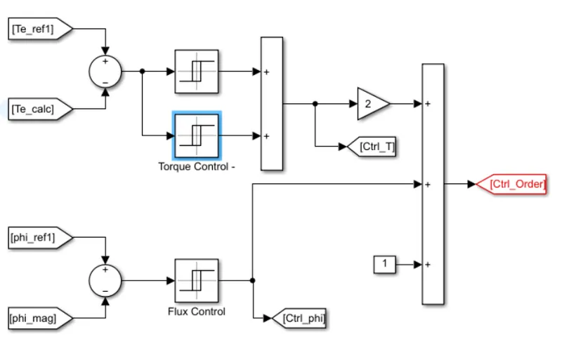
The calculated flux magnitude and torque are compared with the reference values. When the resulting flux or torque error crosses either the positive or negative hysteresis band value, a control signal is activated
in order to correct the error. This Block is totally implemented by using the Saturation blocks for both torque and flux controlling at the output side from this block.
fig(c) Hysteresis control subsystem
Optimal Switching
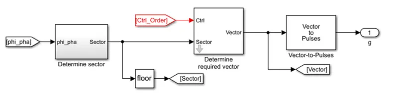
Based on the space vector specified, the block generates pulses for a two-level three-phase converter. Based on the order number coming from the couple(T) & flux (phi) hysteresis controls,
and on the sector number (flux position), the block determines the required voltage space vector (0-7). after Completion of this Control block modeling the Gate pulses are send to the two
level Converter gate terminal. In this way we get the gate signal by using the Control of DIRECT torque Control Method.
6. MATLAB CODE
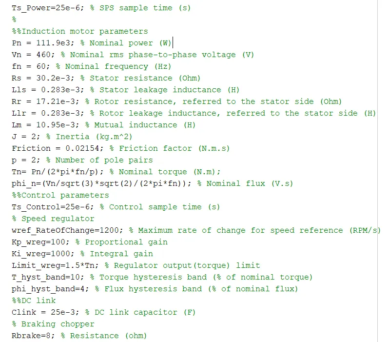
MATLAB code for simulink model with Induction motor, control, choppper, braking parameters which are necessary for the simulink model

fIG(A) Matlab code with induction parameters and other parameters
7. SIMULINK MODEL OUTPUT
Grid voltage and current and DC voltage scope
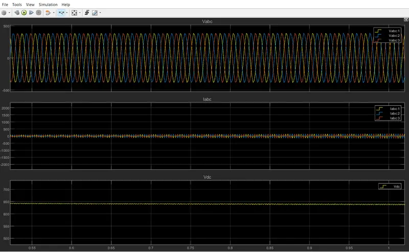
The above scope output have the Grid Voltage (Top Plot) , grid Current (Middle Plot) and Dc voltage (Bottom plot).
The grid voltage has the amplitude of appox 460V. As this is the rated motor voltage. The rated voltage of induction motor is 460V, so the grid voltage must be of 460V, in order to operate it.
Grid current signal stats:
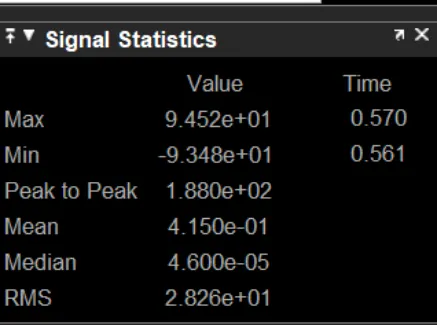
The grid current is at middle plot.The grid current which is the input current to the induction motor. The grid currrent has the maximum amplitude which is 9.452e+01amps. Miniimum current is -9.348e1 A At the time interval 0.561 sec which is the time period.
VDc Voltage plot signal stats:
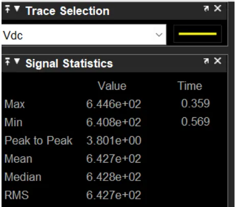
The DC voltage has the Maximum DC voltage which is 6.446e2 V at the time interval 0.359 sec and the VDC also has the Miniimum voltage is -6.408e2 A At the time interval 0.569 sec. This stats are absorbed
from the trace selsection option of the respective plots.
8. MOTOR PARAMETERS PLOTS
SPEED ,Torque ,Phi value and Current OF the Motor :
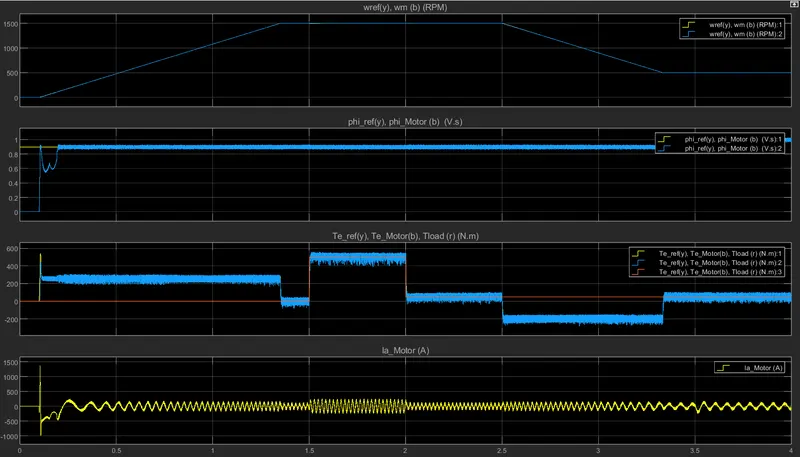
the above plots describes about the motor parameters values representation. The speed plot is been describes as two speeds which are motor speed and refernce speeds. And other plots are troque and Phi values
and motor current. Now its time to discuss them in clear.
Reference speed
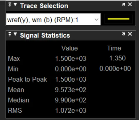
From the above refernece speed the stats are absorbed and they are the Maximum Speed of the reference Signal is 1.500 e3 RPM at 1.50 sec time interval and also the Minimum Speed of reference Signal is 0 at
0 sec time interval.
Motor Speed
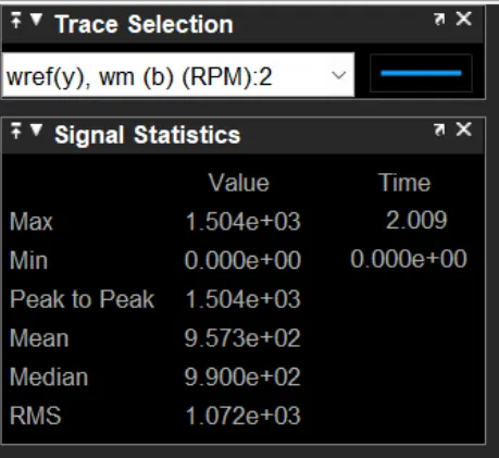
The above plot describes about the motor speed which competes with the reference speeed, so both reference speed and motor speed should match with each other. The Maximum Speed of Motor is 1.5004e3
RPM at 2.009 sec time interval. The Minimum Speed of reference Signal is 0 at 0 sec time interval.
Angle_phi Plot
Reference Phi Plot:
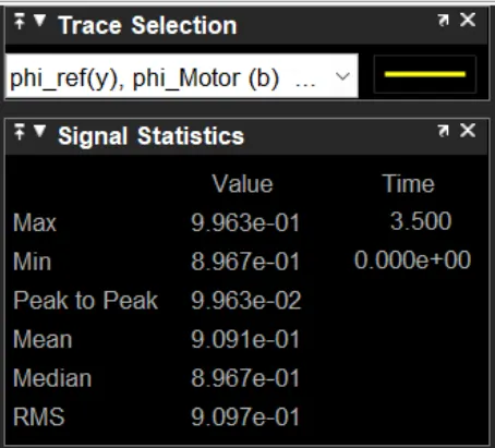
Above plot describes about the maximum Phi value and min value of the angle phi value. The Maximum Phi value of reference is 9.993e-1 at 3.500 sec time interval and the Minimum Phi value of reference is
8.967e-1 at 0 sec time interval.
Motor Phi Value
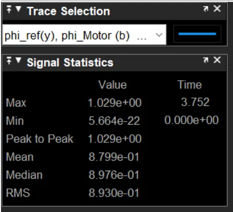
Above plot describes about the maximum Phi value and min value of the motor phi value. The Maximum motor Phi value of reference is s 1.029 at 3.752 sec time interval and the Minimum motor Phi value of
reference is 5.662e-22 at 0 sec time interval.
Torque Plot
Reference Torque:
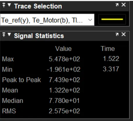
Above plot describes about the refernce torque of the motor, the MAximum Torque is 5.478e2 at 1.522 sec time invertal and the Minimum Torque is -1961e+2 at 3.317 sec
Motor Torque:
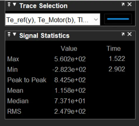
Above plot describes about the torque of the motor, the MAximum Torque is 5.602e2 at 1.522 sec time invertal and the Minimum Torque is -2.823e2 at 2.902 sec time interval.
Load Torque:
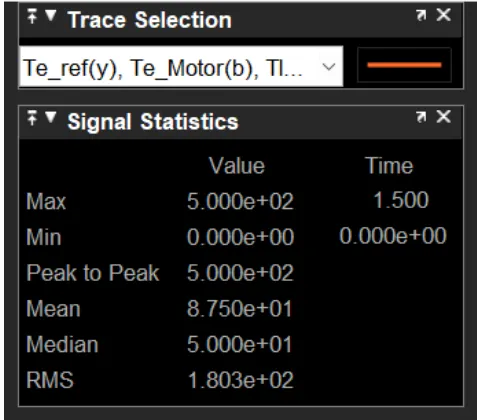
Above plot describes about the load torque value and min value of the load torque value. The Maximumload torque value of is 5.00e2 at 1.500 sec time interval and the Minimum load torque value of
is 0.00 at 0.0 sec time interval.
Armature current
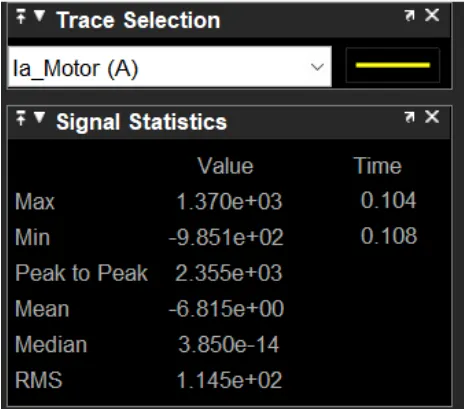
The maximum current drawn by the armature is 1.370e3 Amps at 0.104 sec. The minimum current drawn by the armature is -9.851e23 Amps at 0.108 sec
9. CONCLUSION
The 3 phase induction motor is controlled By using the Direct Torque method is explained with Simulink model. The simulink model is attached below and also this report has been attached with those respective
output plots of motor parameters and other parameters clearly. As the requirement is fullfilled at the end.
THANK YOU