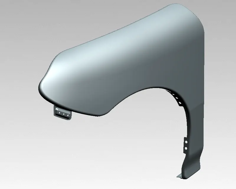
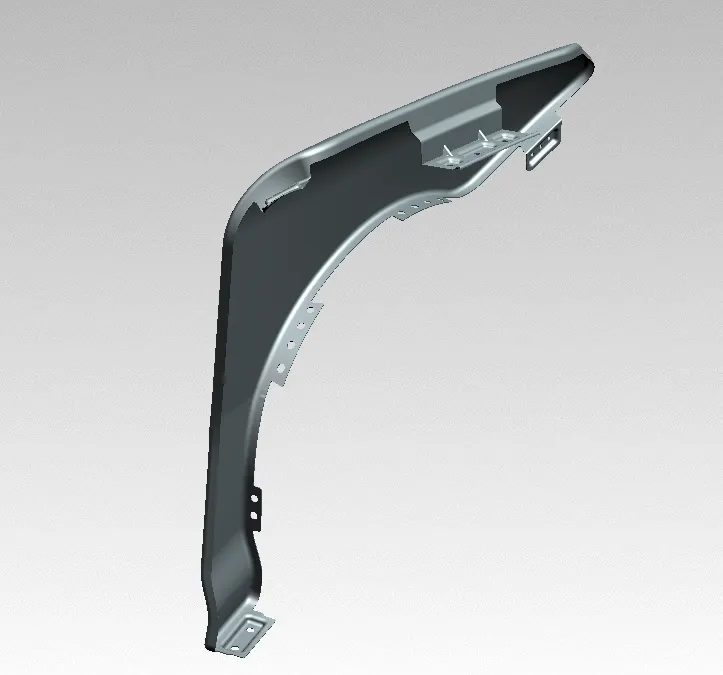
Fender Design Challenge
Objective :
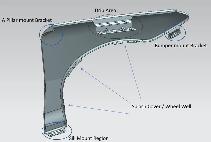
Design a front fender from the given skin data and the master section provided with Drip mounting, A-pillar, Sill, Bumper, C mounting, and Splash mountings.
Consider the front fender of a car that satisfies the manufacturing as well as functional requirements.
To understand the design engineering principles for designing the front fender or body-in-white as an industry aspect.
Software :
Siemens NX / UG NX
Introduction :
Front fender: Fenders are panels on a car that are located on the sides of the car in front of the doors. They serve several functions, not the least of which is aesthetic. The basic purpose of the front fender is to prevent sand, mud, rocks, liquids, and other roads spray from being thrown into the air by the rotating tire. it is a closure component, closing the engine compartment and other compartments.
There are two types of fender
- Full Bumper type
- Half bumper type
Mounting Points on Fender:
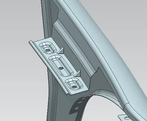
- Drip Area mounting
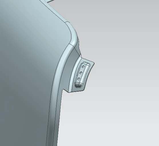
- A pillar mounting
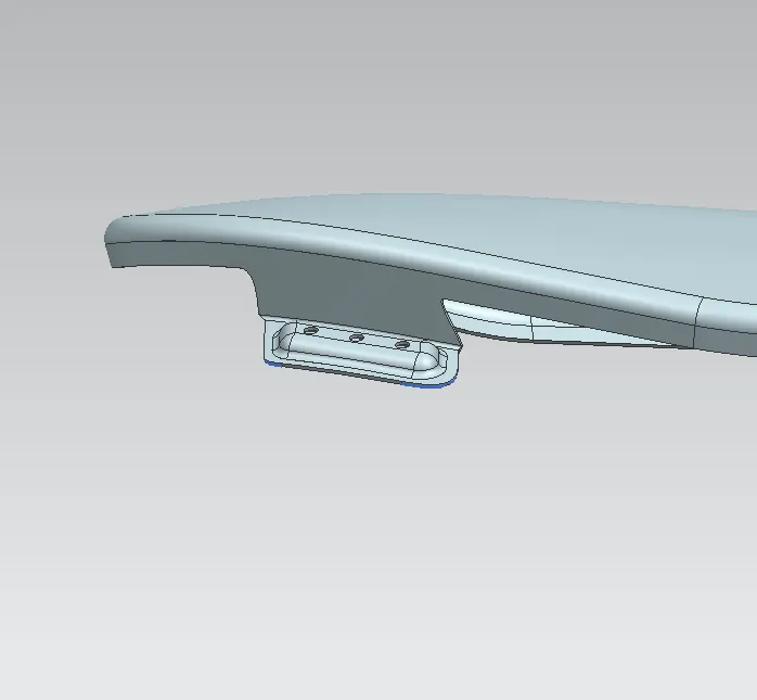
- Bumper mounting
- Sill mounting
- Baffle/wheel arch area
Purpose of fender:
- Cleanliness: Protect the car, occupants, and passersby from items, water, mud, snow, ice, thrown off the tires as you drive.
- Safety: Protects pedestrians from the wheel, e.g. it's better to be it by a laterally moving fender than a rolling tire, keeps loose, streaming items from being wrapped up in a rolling wheel.
- Aerodynamics: smooths the car profile so you don't get a lot of drag off the uncovered wheels. Some fenders are enclosed on the side for this.
- Aesthetic/appearance: looks better with fenders, gives a finished look, looks more streamlined.
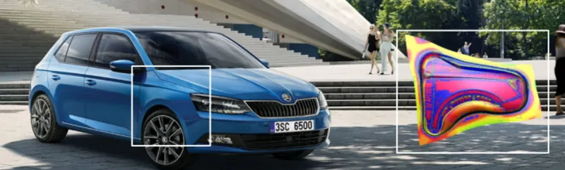
Inputs
- Class A Surface
- Master section
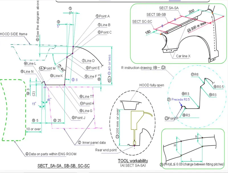
Design parameters:
- While designing the drip area, a 150mm clearance is maintained from the front-end for headlight fittings and a 200mm clearance from the rear-end for the wiper motor assembly (Cowl top area).
- The depth of the drip area is maintained at less than 60mm to avoid the spring-back effect.
- Ribs are provided at the fender drip area to increase strength in that area.
- It is to be observed that no sharp corners persist so that machining can be carried out easily.
- A thickness of 0.75mm is given after all the modeling is done.
Features used in CAD :
- Face blend
- Bridge curve
- Sew
- Dart
- Thicken
- Offset in face
- Edge blend
- Projected curve
- Emboss
- Extend sheet
- Trim sheet
- Intersection curve
- Law extension
- Curve on surface
Design of drip area
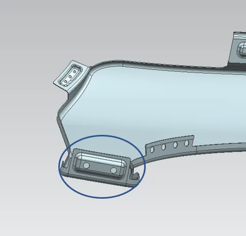
Design of bumper mount area
Design of A-Pillar Mount area
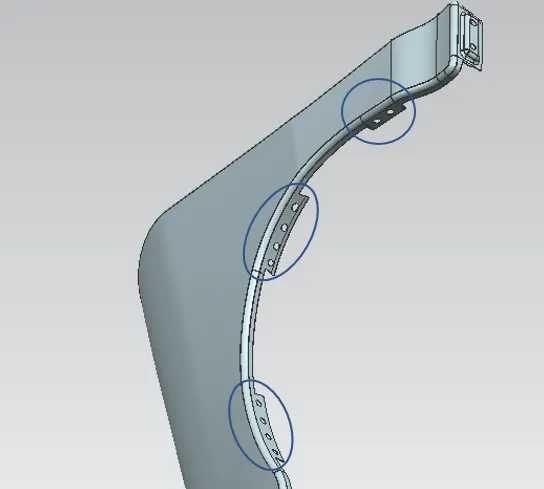
Design of Splash Cover / Wheel Well
Sill Mount Area
Rendering