Design and development of Automotive interior door trim
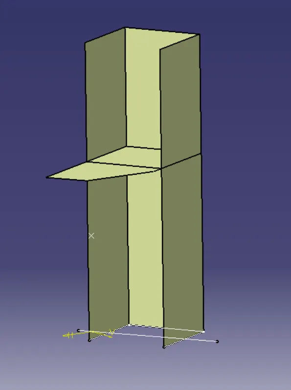
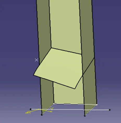
Click here for Master Section Development of B-Pillar
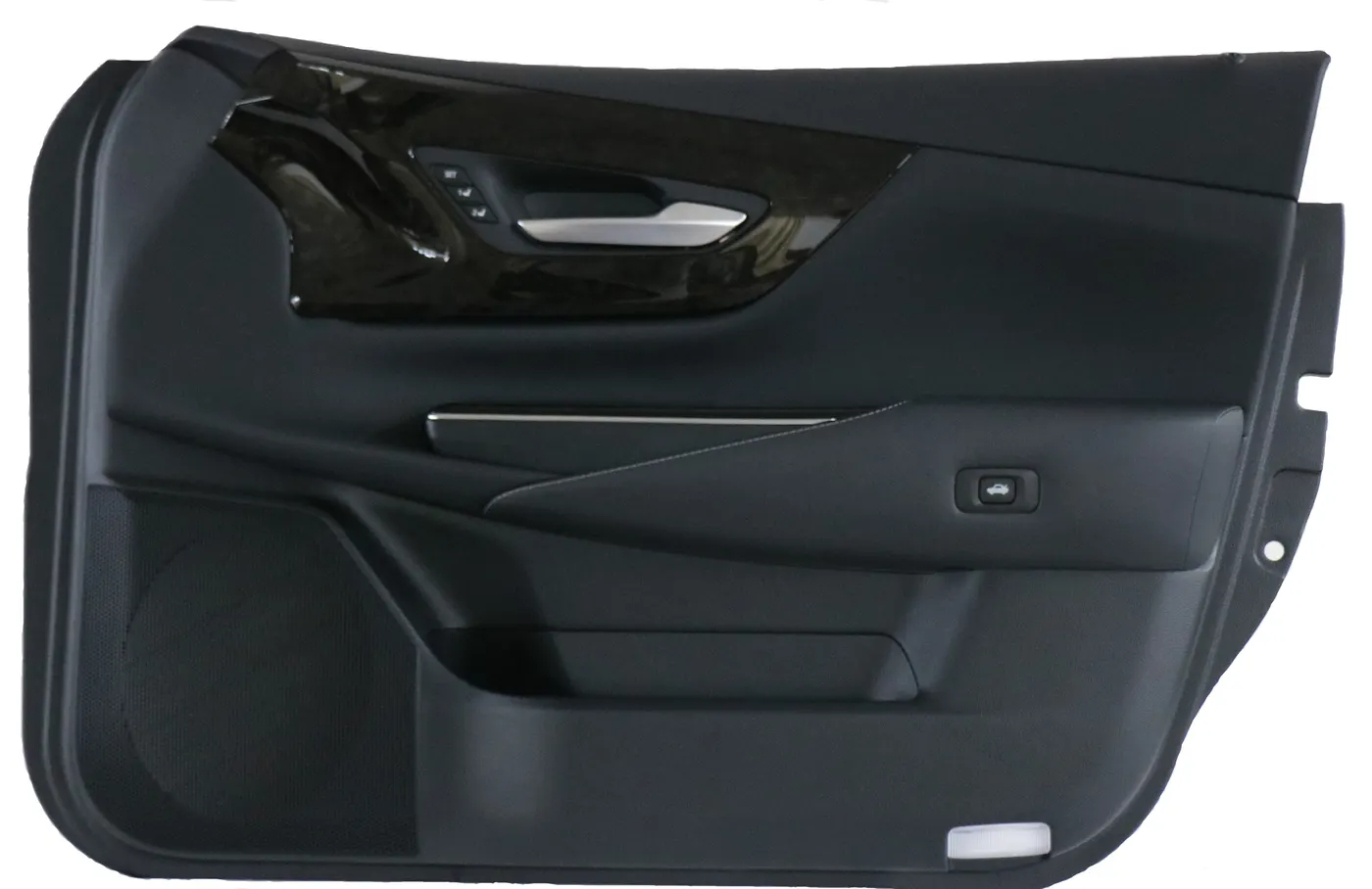
Objective:
- To develop Interior door trim from given Class’A’ surface and master section into a functional product design, following the OEM design standards with the injection molding principles.
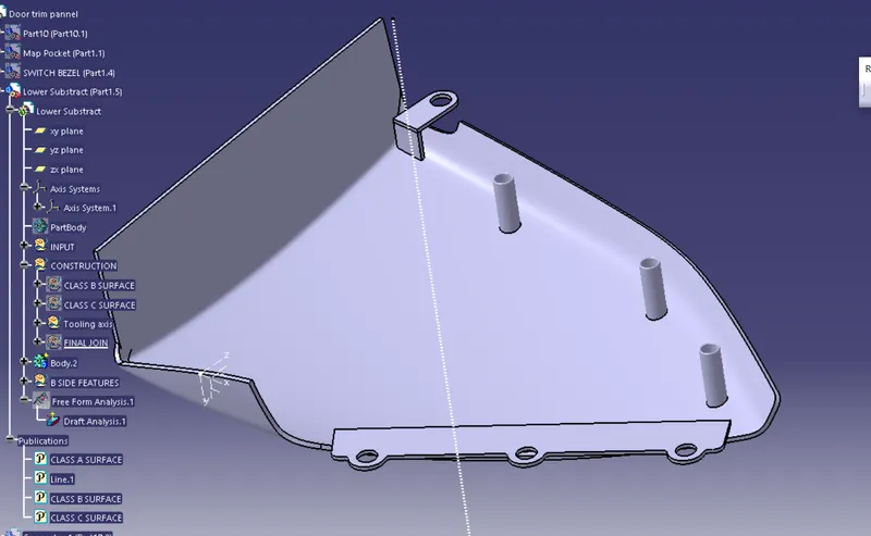
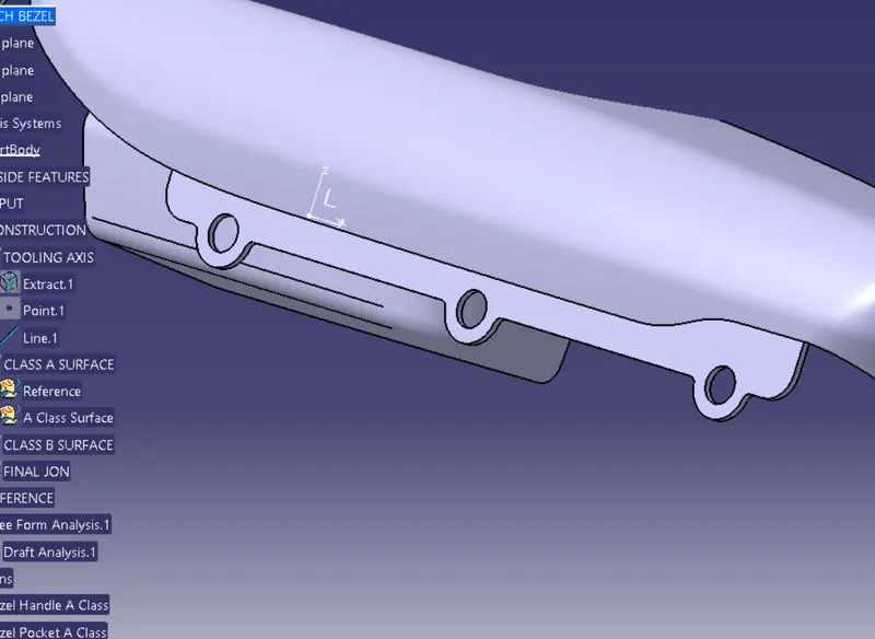
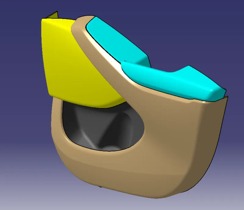
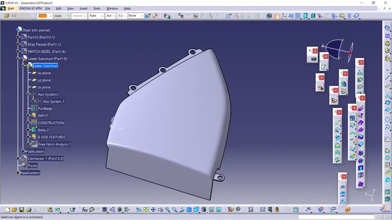
- Design Switch Bezel, Arm-rest, a Lower substrate, and Map-pocket with appropriate dimension.
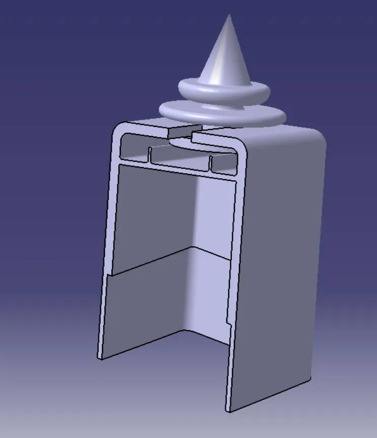
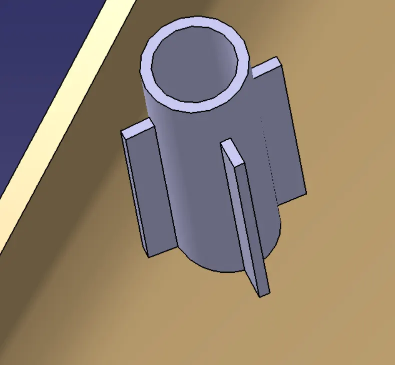
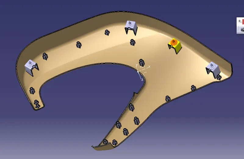
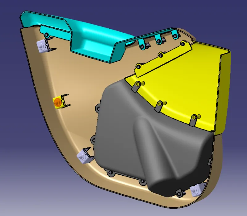
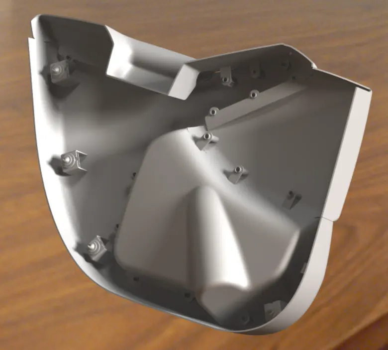
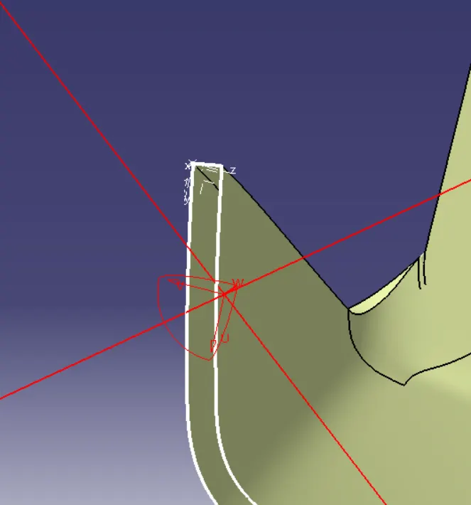
- Create B side engineering features WRT master section such as Dog House, PushPin, Flanges, Heatstake with Ribs.
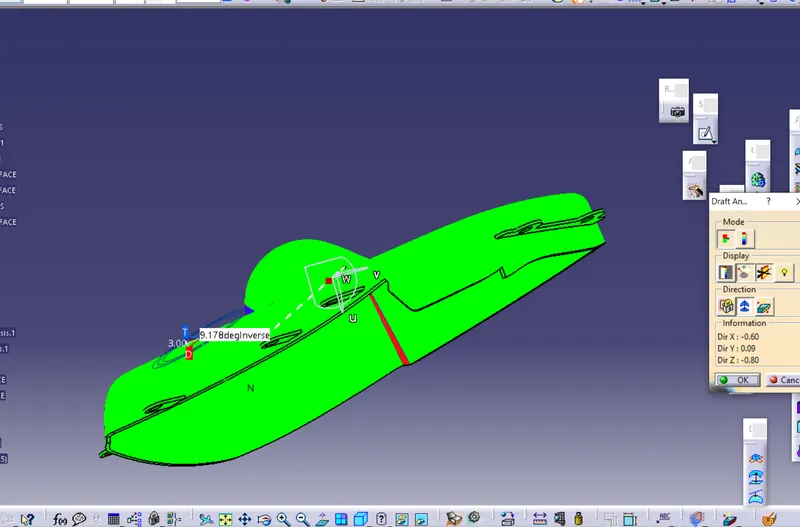
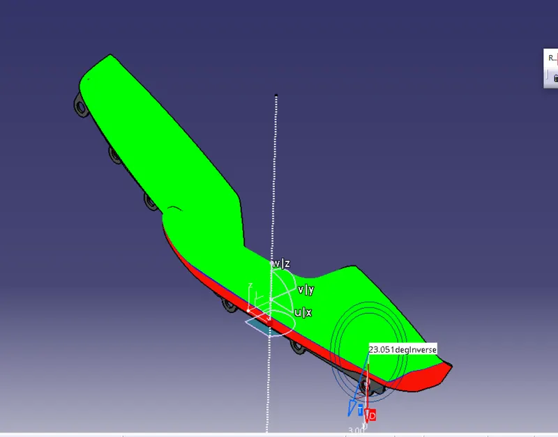
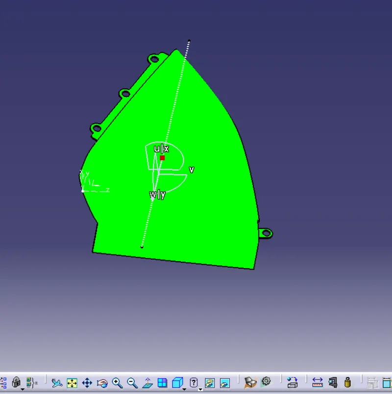
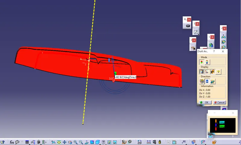
- Find the tooling axis for the given Class-A Surface should be created to meet the requirements of the draft angle.
- Perform the feature Draft analysis on every components and B side engineering features.
- Assemble and render interior door trim
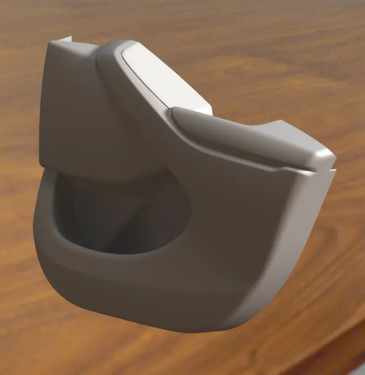
Introduction:
CATIA V5
CATIA is a multi platform 3D software suite developed by Dassault Systèmes, encompassing CAD, CAM as well as CAE. Dassault is a French engineering giant active in the field of aviation, 3D design, 3D digital mock-ups, and product lifecycle management (PLM) software. It is also possible to generate model dimensions and create reference dimensions in the drawing views. The bi-directionally associative property of CATIA ensures that the modifications made in the model are reflected in the drawing views and vice-versa.
Generative Shape Design
It provides an extensive set of tools for creating and modifying mechanical surfaces used in the design of complex shapes or hybrid parts. Its feature-based approach offers a productive and intuitive design environment to capture and reuse design methodologies and specifications. Help to design advanced shapes that are based on a combination of wireframe and extensive multiple surfaces. It includes high-level features with full specification capture and reuse.
The Methodology I followed to get a successful Door Surface is divided into 3 parts which are further divided into sub-classes.
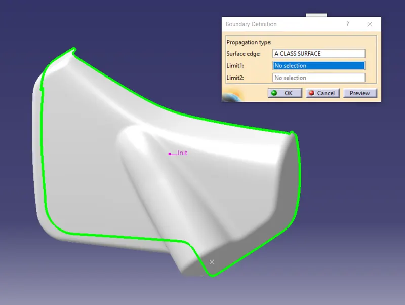
- Checking the Class –A Surface
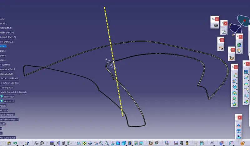
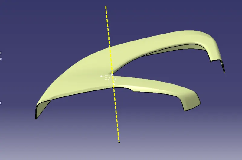
- Segregating the Class-A into Map Pocket, Lower Substrate, Arm Rest, and Master Sections.
- Dividing the Map Pocket and the Arm Rest into two Parts.
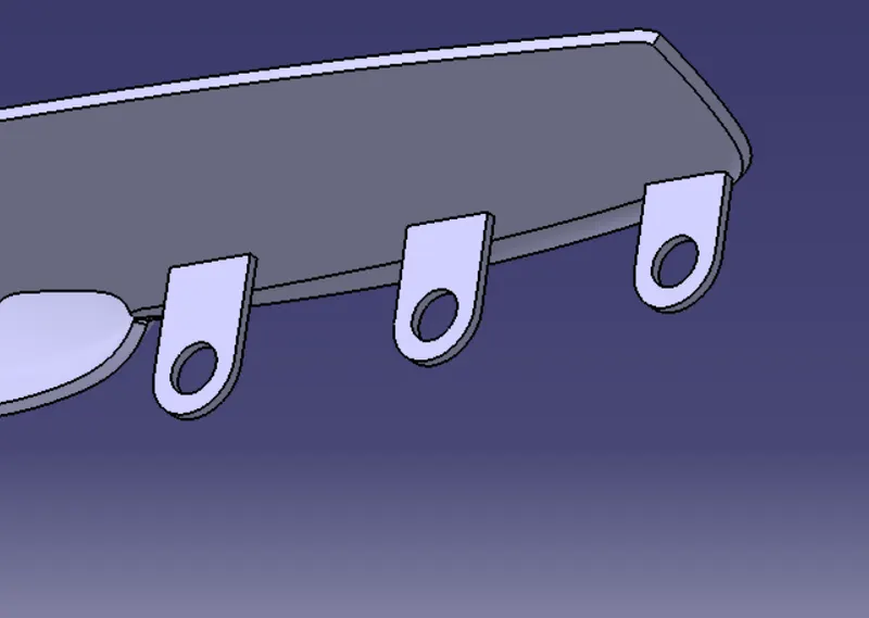
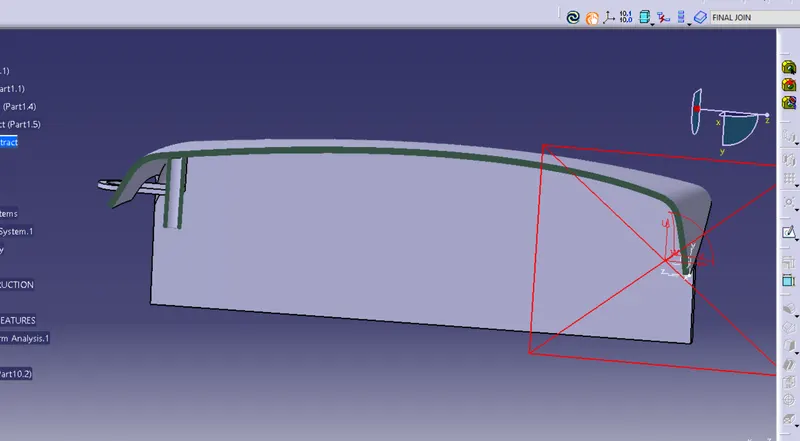
- Creating the Required Flanges for Arm Rest and Map Pocket.
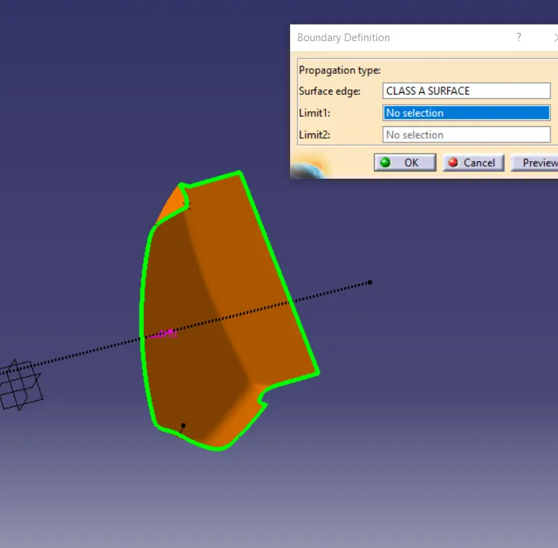
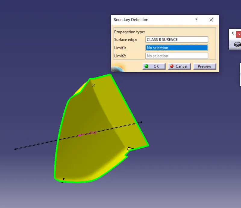
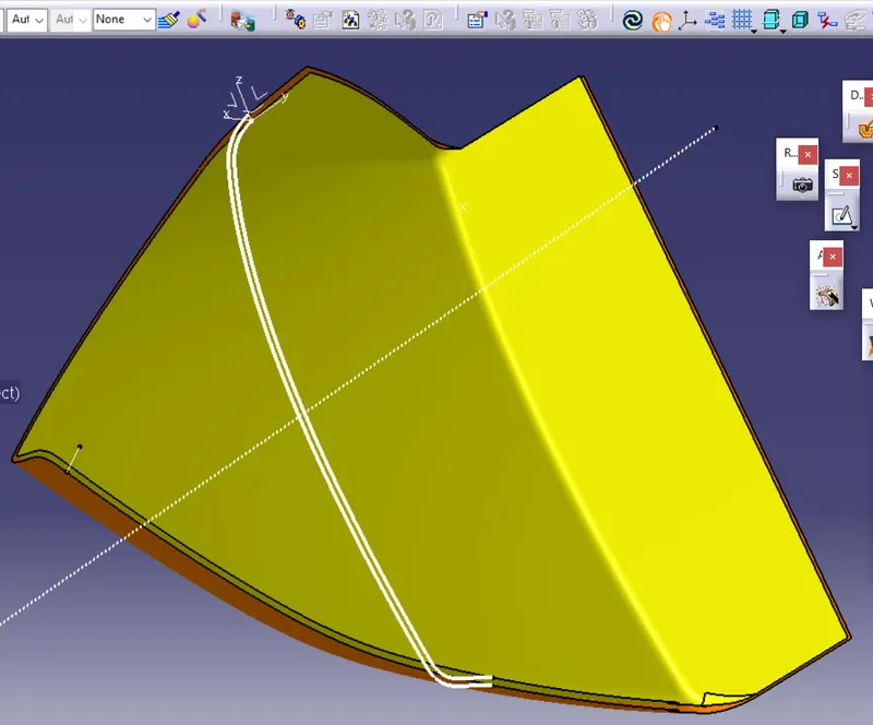
- Generating the Class B Surface.
- Creating the Class C Surface.
- Joining the Surfaces.
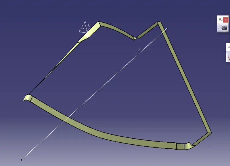
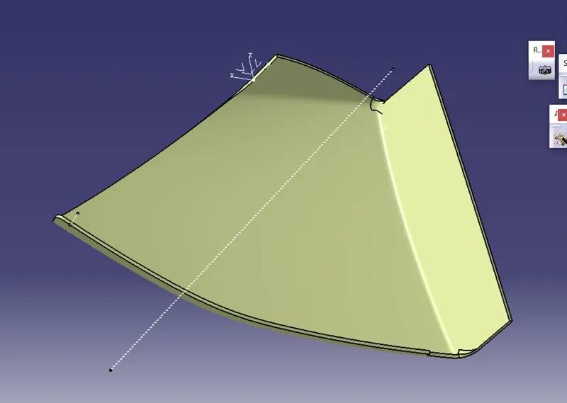
- Generating the Solid.
- Creating the B Surface Features such as Heat Stakes, Dog Houses, and Push Pins.
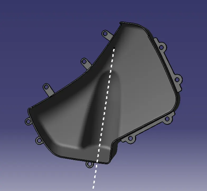
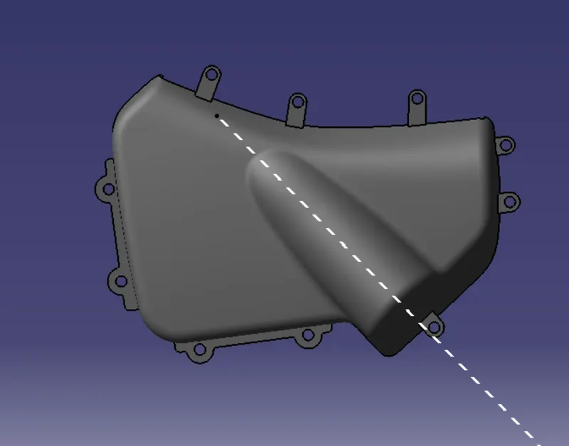
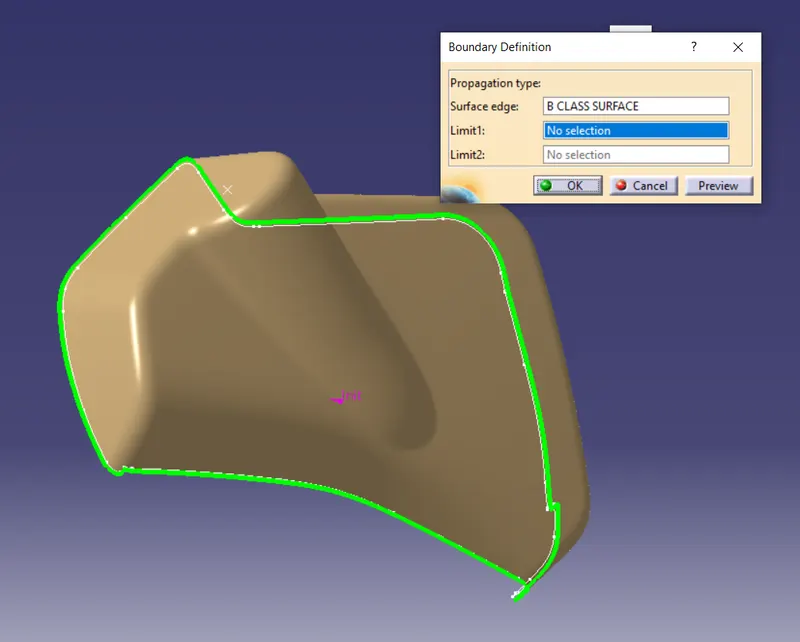
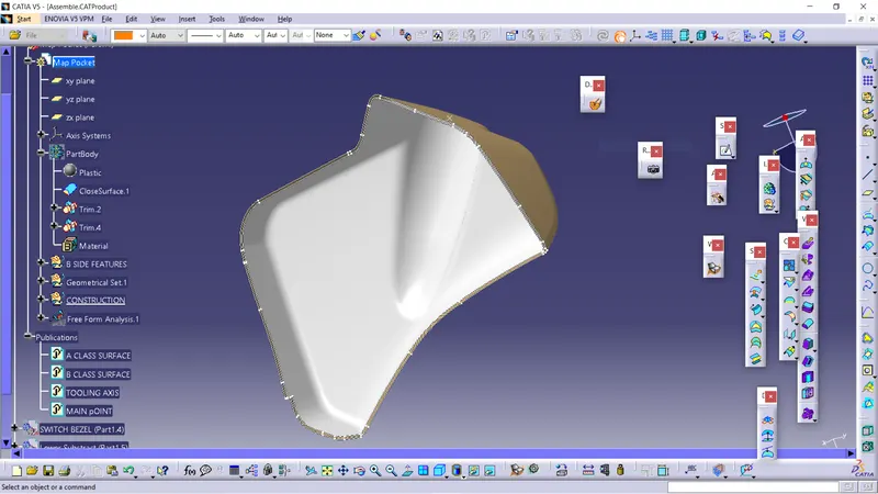
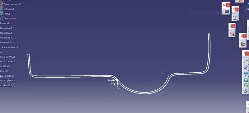
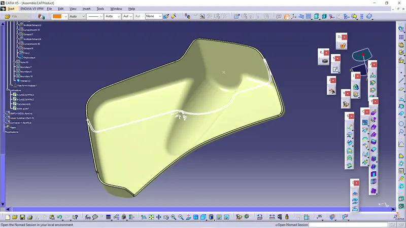
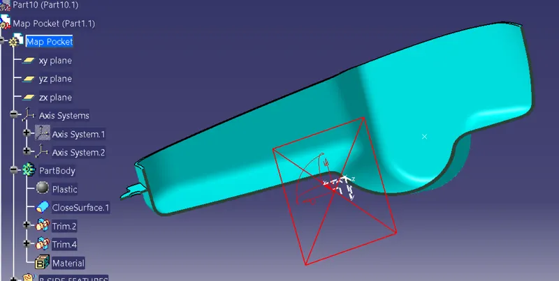
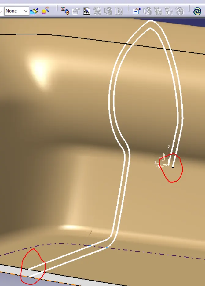
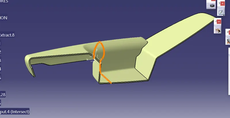
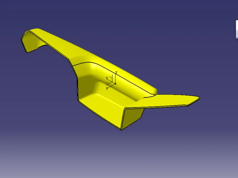
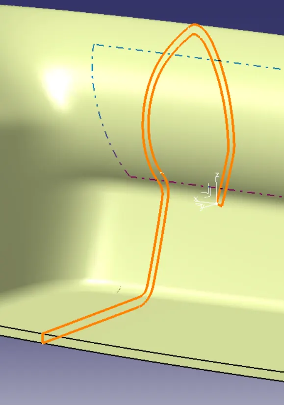
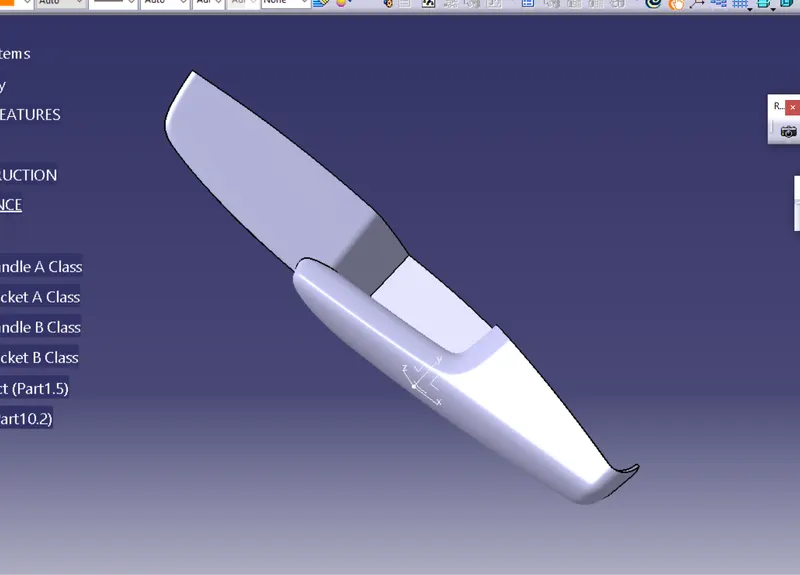
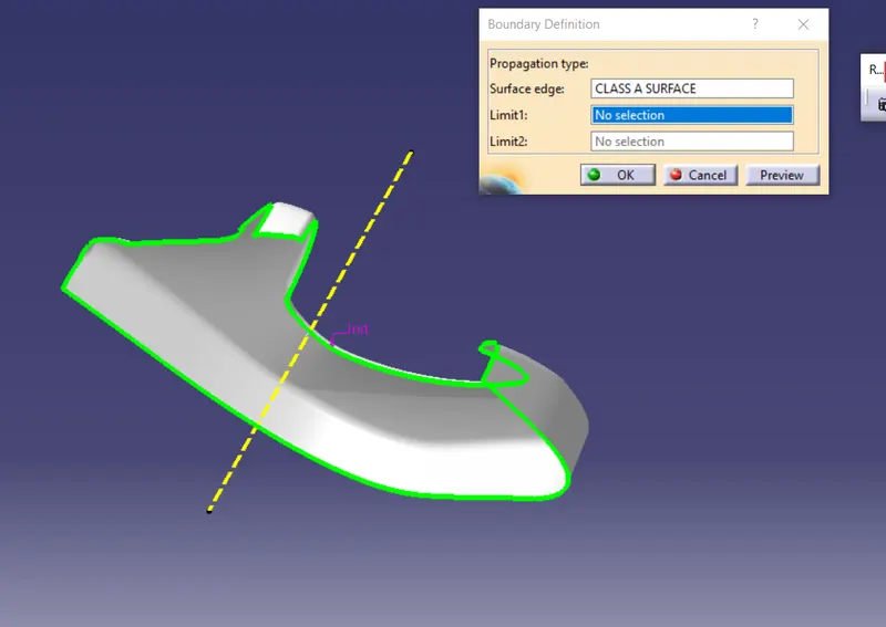
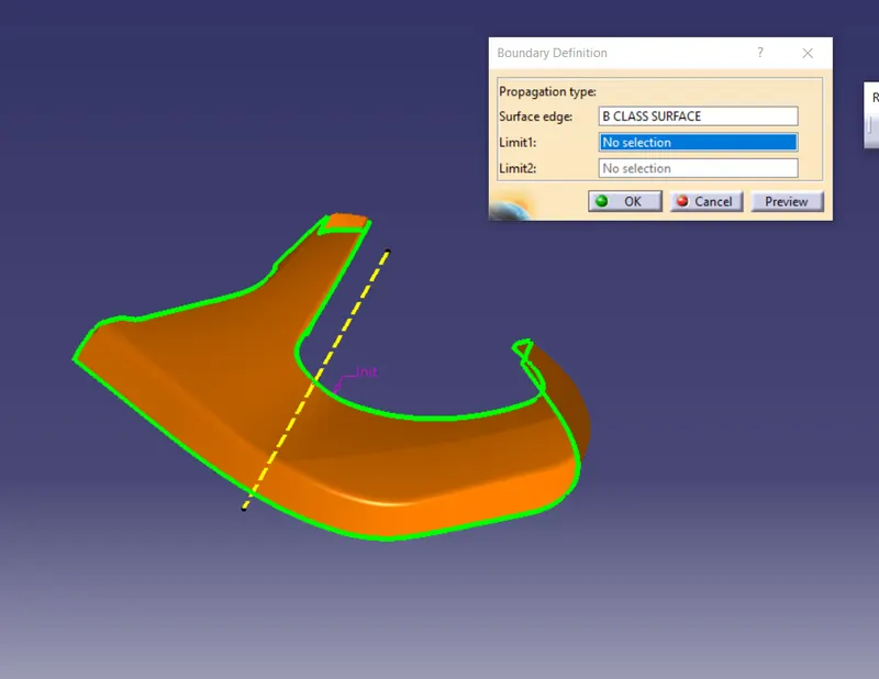
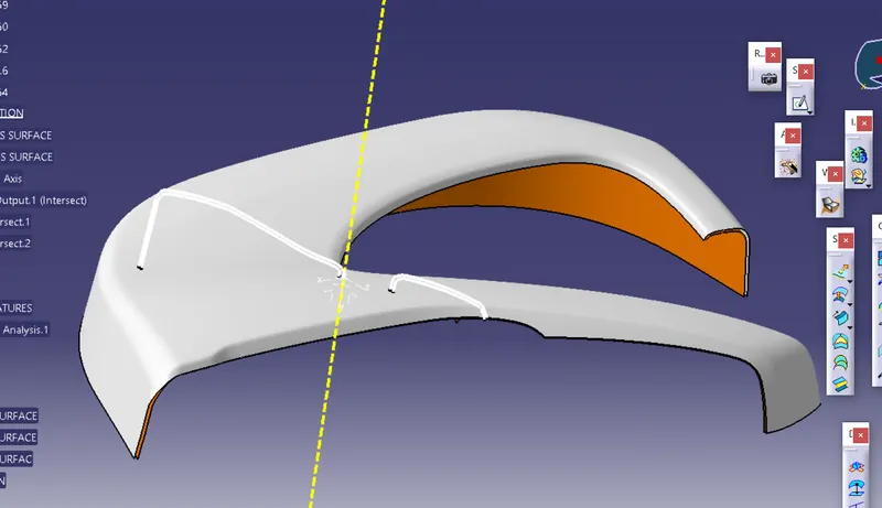
Map Pocket
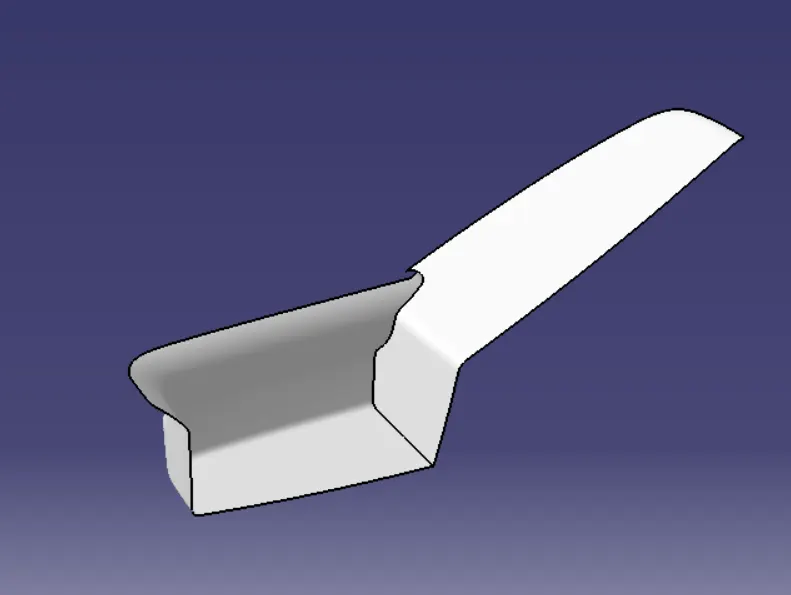
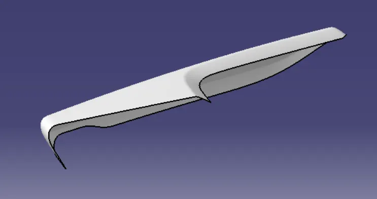
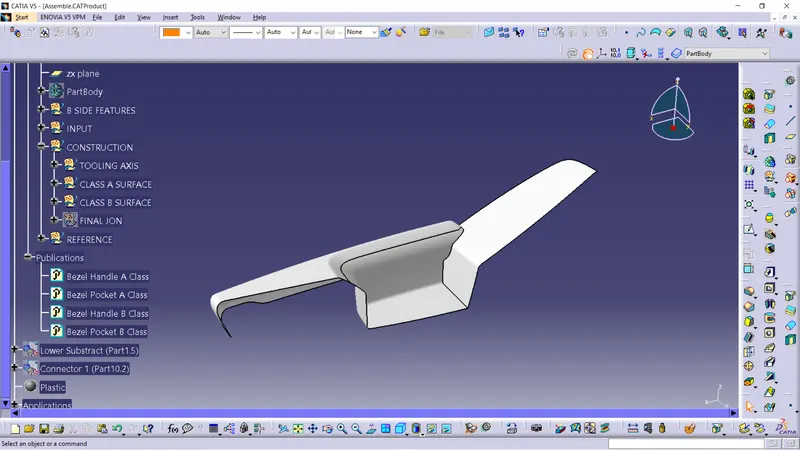
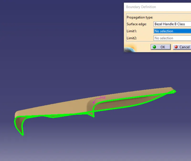
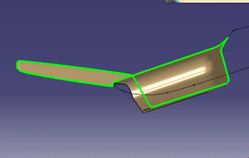
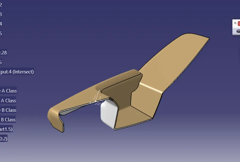
switch bezel
B Side Engineeering Features
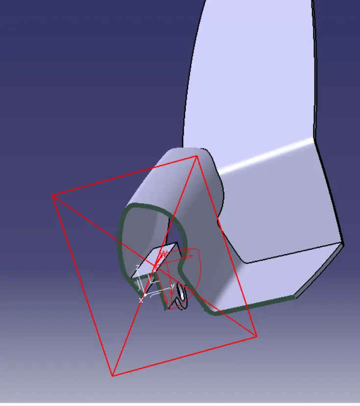
Dog House