Design and develop Automotive Hood by following euroNACP standards
Objective
- To design Hood outer panel, inner panel, and the necessary reinforcements by following the Master section mentioned with the design parameter.
- The inner panel and outer panel of the hood must be designed and assembled with the Hinge Assembly, Latch, and Striker with their reinforcements.
- Consider the Hood of a car that satisfies the manufacturing requirements, functional requirements, and as well as Euro NCAP standards.
- To understand the automotive engineering principles for designing the inner panel or body-in-white of the hood as an industry aspect.
Software
Siemens NX / UG NX
Introduction
Siemens NX:
Siemens NX software is a flexible and powerful integrated solution that helps you deliver better products faster and more efficiently. NX delivers the next generation of design, simulation, and manufacturing solutions that enable companies to realize the value of the digital twin.
Hood / Bonnet:
The hood/bonnet system is an access panel to the engine compartment to enable maintenance of the power train, drive belts, battery, fluid levels, and lamp units. It is fundamentally a reinforced skin panel with many safety and quality requirements. Reduce damage of pedestrian considering head impact, associated with a low-speed crash with a pedestrian. Protect the underlying parts and the motor from theft. Protect parts under the hood from environmental damage, like corrosion and water. Give the car better aerodynamics and a good look with styling.
Euro NCAP:
The European New Car Assessment Programme (Euro NCAP) is created the five-star safety rating system to help consumers, their families, and businesses compare vehicles more easily and to help them identify the safest choice for their needs.
Hood Development Parameters
- Head clearance zone
- Pedestrian Safety
- Consideration of Noise Vibration Harshness (NVH)
- Vehicle Quality
- Occupant safety
- Styling
- Manufacturing
Head clearance zone:
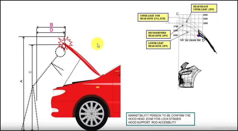
The head clearance zone is the clearance such that when the hood is in fully open condition it does not hurt the head of the person that is standing next to the hood. this is controlled by the opening angle of the hood. the opening angle of the hood is decided for the region the car is manufactured. some regions may have people with an average height of 5.5 ft and another region may have people with an average height of 6 ft . so deciding the right opening angle for the hood is an important criterion.
Pedestrian Safety:
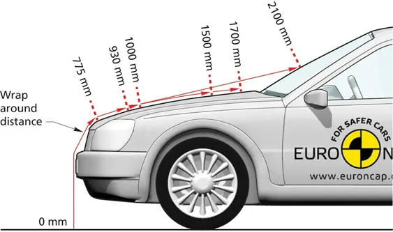
According to the requirements of the Australian New Car Assessment Program (ANCAP) for pedestrian protection, it needs to define zones of car hood for analysis, as shown below Figure. It can be noted that when the collision projection point locates between (Wrap Around Distance) WAD 1000 and WAD 1500, the head type will use the children's head type. The adult head type will be used while the collision projection point locates between WAD 1700 and WAD 2100. In the collision projection point located at WAD 1000 when the children's head type will be used
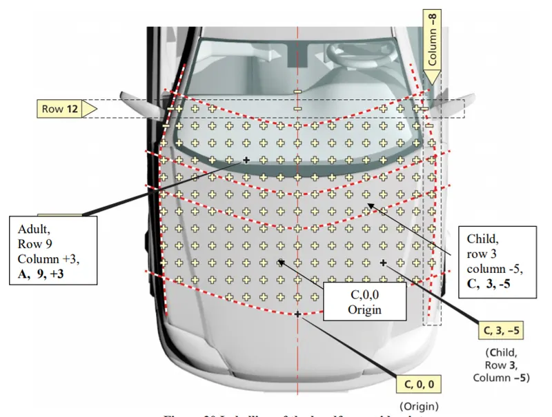
The Head Injury Criterion (HIC) indicates a measure of a head injury arising from an impact, which is evaluated by the impactor in terms of the simulation of the child's head. HIC includes the effects of head acceleration and the duration of the acceleration. ANCAP provides measures for the assessment of pedestrian protection performance of a passenger car experimentally by firing subsystem impactors representing a child head, adult head, upper leg, and lower leg at a specified angle and speed to the front end of a stationary vehicle. The resulting injury measures from these physical tests are assessed against the bounds specified by the protocols.
Consideration of Noise Vibration Harshness (NVH)
NVH plays an important role in car design. the noise and vibration produced by the car should be minimized. in the hood, to avoid vibrations stiffener pads are provided. mastic sealants also reduce the NVH. stiffener pads and mastic are added between the inner and outer panels of the hood.
Vehicle Quality:
The material selection followed with its manufacturing feasibility giving optimum results to mechanical properties benchmarking is the key factor for vehicle quality. Hood materials are manufactured generally using steel, aluminum alloy, or composite material like fiberglass/carbon fiber. Various factors are considered like analysis of torsional stiffness, dent resistance, corrosion resistance, bending stiffness, noise attenuation, etc.
Occupant safety:
The hood panel is designed in such a way that, during the crash, the hood section deforms completely so that the maximum impact of the crash is absorbed by a hood to get deform and divert collision forces away from the cabin. This helps to properly damp the force to avoid or reduce the risk of injuries and death.
The deformation is achieved by designing the hood in a two-piece that is outer panel and inner panel separated by mastic sealants. Thus the cavity between the panel and the blanking in the inner panel acts as the weakest section to get deform while crashing. The impact of the crash is diverted to hinges which are reinforcement plates
Styling:
The styling team designs the outer skin or class A surface of the car hood considering the major factor that often influences vehicle sales in the market. The outer panel is the main consideration here as it is the only component that is visible outside. The factors such as surface quality, tight radii on hemmed panel edges aesthetic design, etc. are crucial. Other than styling, aerodynamic factors are important while designing the outer panel.
Manufacturing:
In the manufacturing of car hood various sheets, metal operations are carried out like profile cutting of sheet metal, blanking, piercing followed by deep drawing and hemming process. In the manufacturing of inner panel embossed surfaces are achieved by deep-drawing where a minimum 7mm degree drat angle is maintained respectively to the tool direction. fix cutout for jig and fixture with a distance of more than 5 mm from emboss corner.
Manufacturing process
Blanking:
Blanking is a metal fabricating process, during which a metal workpiece is removed from the primary metal strip or sheet when it is punched. The control of the quality by the punch and die clearance. The ability to produce holes of varying shapes quickly.
Deep drawing:
Deep drawing is a sheet metal forming process in which a sheet metal blank is radially drawn into a forming die by the mechanical action of a punch. It is thus a shape transformation process with material retention. The process is considered a "deep" drawing when the depth of the drawn part exceeds its diameter. We give a positive draft or an angle for a better drawing process. Process definition: The deep drawing process is a forming process that occurs under a combination of tensile and compressive conditions. A flat sheet metal blank is formed into a hollow body open on one side or a hollow body is formed into a hollow body with a smaller cross-section.
Trimming:
Trimming is a manufacturing process that is used as a finishing operation for forged parts, to remove flash. Most often it is desirable to perform this operation while the work is still hot for maximum efficiency, therefore it is usually incorporated into the larger production process.
Hemming:
Hemming is a sheet metal forming process in which sheets are joined by bending it usually to 180°. Automotive body panels and automotive parts such as deck-lids, trunk-lids, doors, hoods, and tailgates are formed by the hemming process. Hemming is a forming operation in which the edges of the sheet are folded or folded over another part to achieve a tight fit. Normally hemming operations are used to connect parts, to improve the appearance of a part, and to reinforce part edges.
Input Data
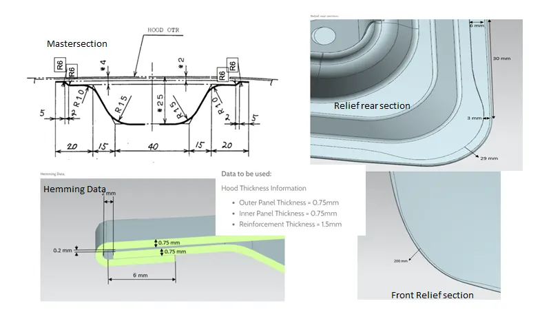
Design Approach
In this project, the Top-down approach was used because the styling surface and reinforcements were already designed. Hence by creating the assembly then the hood inner panel was designed and the embosses for positioning the hinge assembly, latch, and striker were created. With top-down approach users start to design a product by defining but not detailing its first-level components. Each component is then refined in more detail by defining its sub-components. The process is continued till all low-level components are defined and detailed.
- Hood assemble
- Outer Panel design
- Inner panel design
- Constrained Hinge
- Latch and striker positioning
Design Methodology
- Assemble for the top-down approach
- Importing Class -A Surface of the outer hood.
- Surface design of Inner hood section.
- Design of Reinforcements, and Mastic Data.
- Assembly alignment inner hood with hinges.
- Thickening of the inner hood panel to 0.75mm.
- Assembly of Stricker to inner hood embossed profile to position open and close trajectory concerning hinge axis of rotation.
- Surface design of outer hood section with hemming parameters.
- Providing reliefs at corners to reduce stress concentration.
- Thickening outer hood panel to 0.75mm.
The features used for hood assemble
- Offset surface
- Offset curve in the face
- Trim sheet
- Through curves
- Project curve
- Law extension
- Trim and extend
- Extend sheet
- Face blend
- Edge blend
- Mirror geometry
- Sew
- Thicken
Inner panel
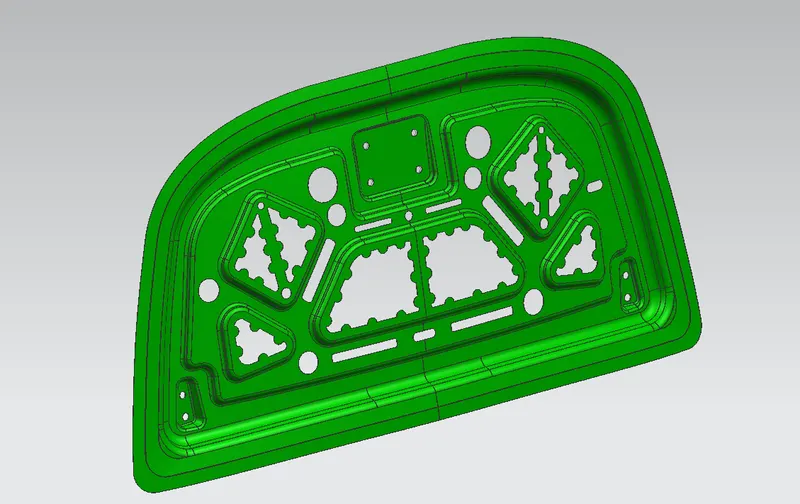
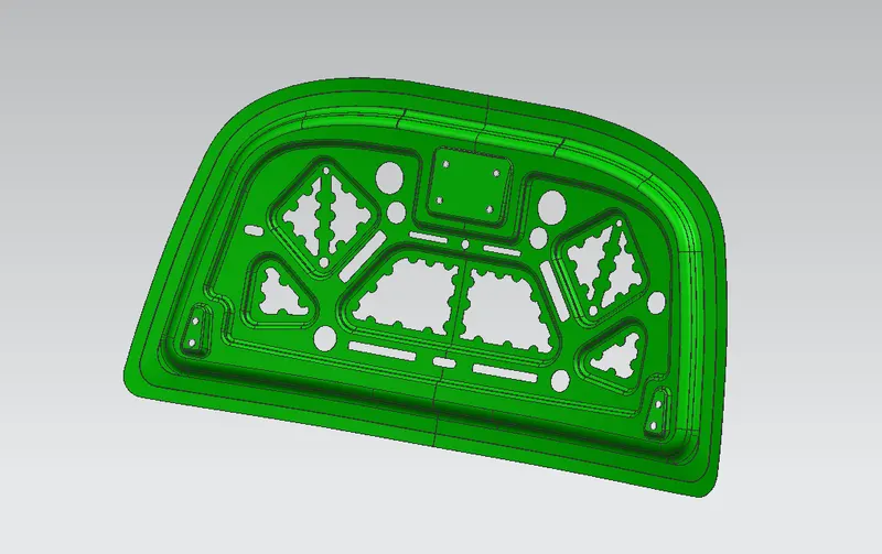
The inner panel supports the outer panel. It consists of different embosses and holes at different places. Embosses provide stiffness as well as dissipate energy towards hinges. To determine the most effective position of the hole, the method of modal stiffness is employed.The inner panel is an offset of the parent work surface.inner panel thickness is 0.75mm
Methodology
- By using the wave geometry linker the styling surface will be extracted as a linked body.
- The styling surface was trimmed in half using the trim surface along x co-ordinate.
- Then two surfaces at the offset of 0mm were generated and one feature was grouped as a parent file and the other one was used as the working surface.
- By using the master sketch three surfaces were off-set at a distance of 2mm, 4mm, and 25mm downwards.
- For creating the 5mm flange the corner of the tangent curve will be offset inwards at the distance of 20mm with a 30mm filleted corner and the remaining portion was trimmed.
- Then for creating the next flange the second offset surface was trimmed at a distance of 40mm.
- By using through curves both the surface were connected to create a flange at an outward angle of 80 degrees as per the manufacturing parameter.
- Then the third surface was trimmed and used to create the flange at a distance of 55mm.
- Then the required embosses were created to reduce the transmission of force and it should satisfy the requirements of NASC regulations and the embosses must have an outward draft to satisfy the tooling direction.
- The below diagram represents the ideology of the design, the orange line represents the direction of force dissipation when the hood attempts an unexpected crash.
- Then by using the edge blend and face blend all the sharp corners were blended and smoothened out as per manufacture requirements.
Embossing
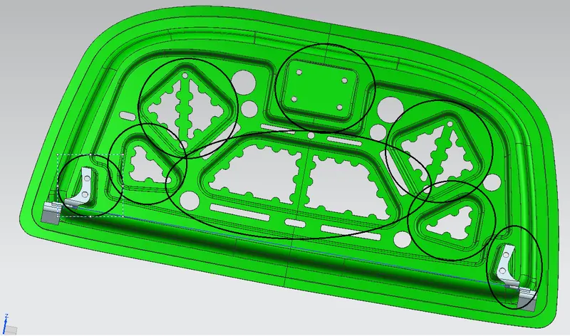
The geometry is created based on the master section that was designed above. After performing the initial stages of design, we will provide local embosses to strengthen the component. The component will be strengthened based on the master section. When a force impacts the hood from the front, it travels in an upward direction. The component is designed to divert the force away from the passengers into the hinges and it is a stamping process for producing raised or sunken designs or relief in sheet metal. This process can be made utilizing matched male and female roller dies or by passing a sheet or a strip of metal between rolls of the desired pattern. It is often combined with foil stamping to create a shiny, 3D effect. It is also made that when the car is crashed the force will be passed to the cabin. If emboss are made, the forces are made passed or divided through embosses to hinge, so the passenger inside the car will be safe. as shown in the black circle in the image below The embosses in the inner panel are made according to the diversion of the load path. The emboss depth is kept at a maximum of 5mm to be on the safer side so that the part is manufacturable.
Mastic Data
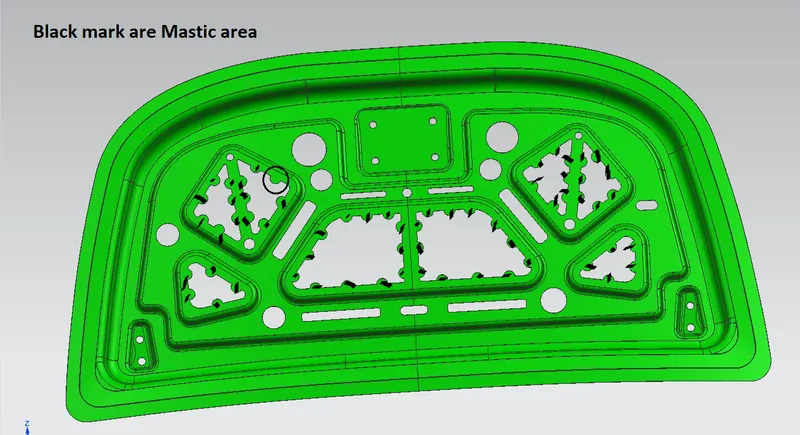
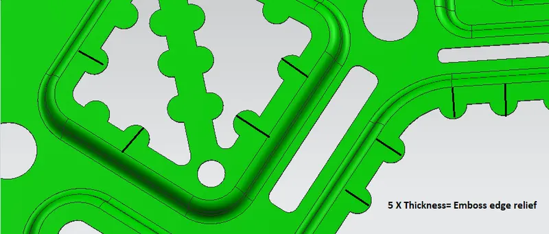
It is basically a Noise, vibration, and hardness NVH parameter where mastics are provided inside the embossed surface between the gaps of the outer panel and inner panel of the hood to achieve the best NVH value. Lower the value better the NVH rating. So, mastic sealants are filling adhesive material used to occupy vacant space between inner and outer panels to reduce the NVH value. One spot of mastic sealant covers and provides strength to around 80mm diameter. Here black mark represents the surface area covered by mastic sealant inside the hood body. Semicircle profiles are provided on the edges of cut out to place the mastic sealant.
Outer panel
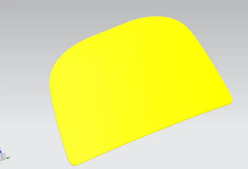
an outer panel that ridges both the outer panel and interior trim.The design of the outer panel is mainly inspired by aesthetics but there is some engineering also to it. Here the main purpose of the outer panel is to cover the inner panel to provide an aesthetic look at the same time Panel must be curve & sleek so that it behave aerodynamically and air hitting from the front reflects it efficiently.
Methodology
- The hood outer panel was created by creating an offset surface from the styling surface and then trimmed in half.
- Then for creating the Hem flange about 6mm around the outer panel for creating the hold with the inner panel.
- Then law extensions were used on the outside curve and the generated surface was offset to 6mm and then the remaining portions were trimmed.
- By using the Face blend the hem flange was created.
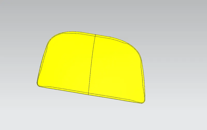
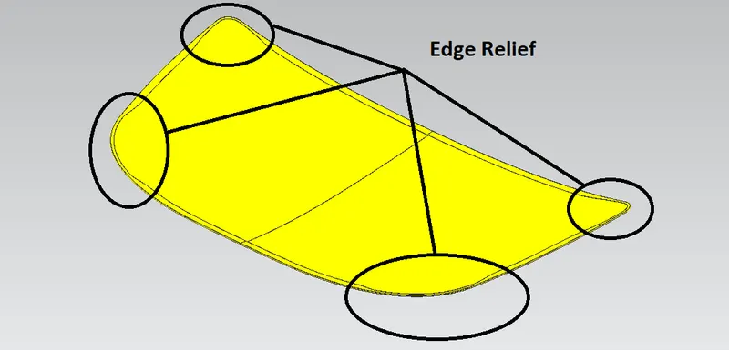
- By using the curve on the surface and trim sheet the required corner relief was provided on the top and bottom corner as a requirement.
- Now the other half was mirrored and sewed together.
- Below figures will show the section view of the hood assembly which explains the tolerance, smoothness, and face intersections were achieved as per the manufacturing requirements.
Hemming
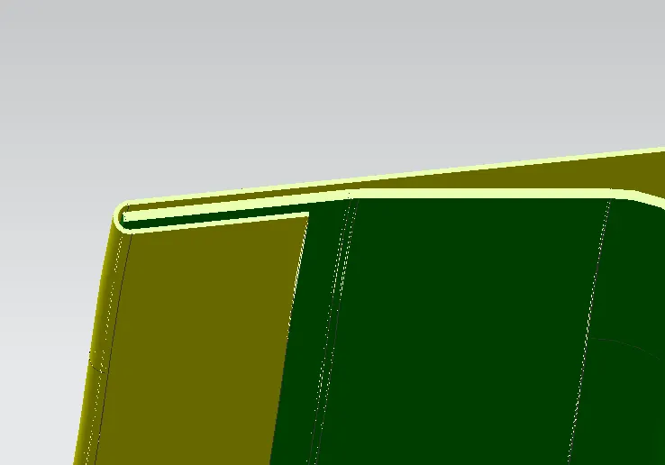
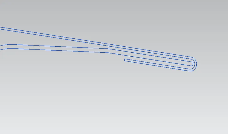
Hemming is the process in which the edge is rolled flush to itself, while a seam joins the edges of two materials. Normally hemming operations are used to connect parts, to improve the appearance of a part, and to reinforce part edges. In hood design, hemming is used in assembly as a secondary operation after deep drawing, trimming, and flanging operations to join two sheet metal parts (outer and inner) together. Dimensions of hemming are given below.
Relief data:-
Relief is provided onto the part or component in order to remove any stresses developed in a particular area i.e sharp corners that take place during the hemming process are carried out. Thus corners are rounded or chamfered.
Hood Opening and Closing Trajectory
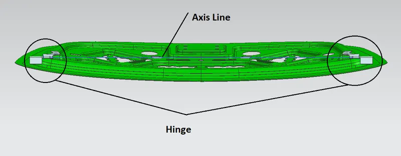
The trajectory for opening and closing is considered to be proper when the striker's axis is coincidental with the hood center axis. The perpendicular line from this axis is selected from the hinges on either side.
Positioning the hinge assemble
A hinge reinforcement pad is assembled on the hood inner panel to increase the local torsional stiffness and providing provision for permanent reverting of hinges to the inner panel. The thickness of 1.5mm gauge sheet metal was used to stamp it according to the embossed cavity profile of the hood inner panel hinges mounting area. These pads are assembled to the inner panel via spot welding/laser welding technique for a better surface finish.
Methodology
- The hinge assembly was positioned by applying the required constraints.
- First, the inner panel was fixed and then a line was created horizontally connecting the hinges, and then the hinges were constrained with a parallel mate.
- The back surface on the hinge hood part was touch/align with the top surface of the hinge emboss on the inner panel.
Positioning latch and strikers
- First, the latch was positioned roughly using the constraints and by exporting the back surface of the latch using a wave geometry linker.
- Then by using the linked surface the emboss for the latch was created but before doing that the linked surface must be extended all around for creating clearance for the edge blends.
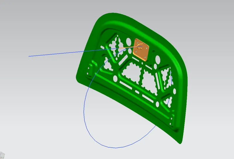
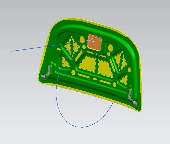
- Now the required circle from the center point of the hinge axis was created and a line tangent to the circle and a line vertical to the striker point from the latch were created.
- Now both the lines were aligned together and then the latch will have its perfect position for striking with the engine compartment.
- The orange line from the below figure represents the vertical line created from the latch and the blue line was the tangent line of the circle.
- Now if we move the hood as closing then the striker will meet the exact location of the striker point in the engine compartment.
Conclusion
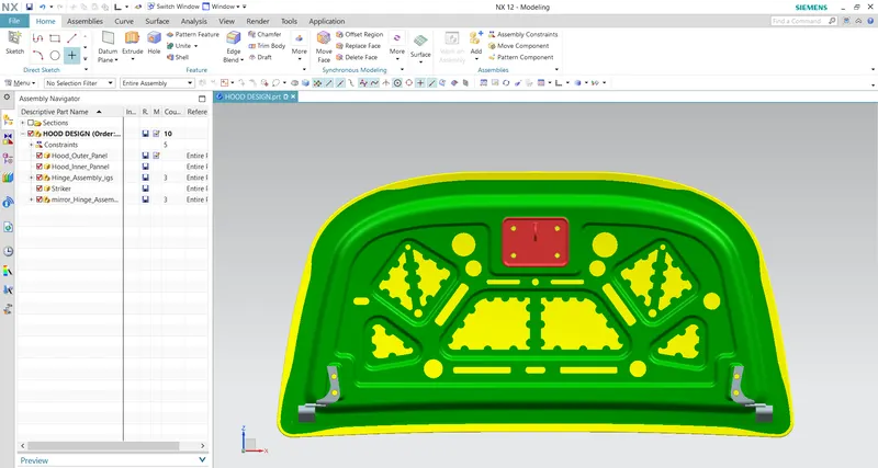
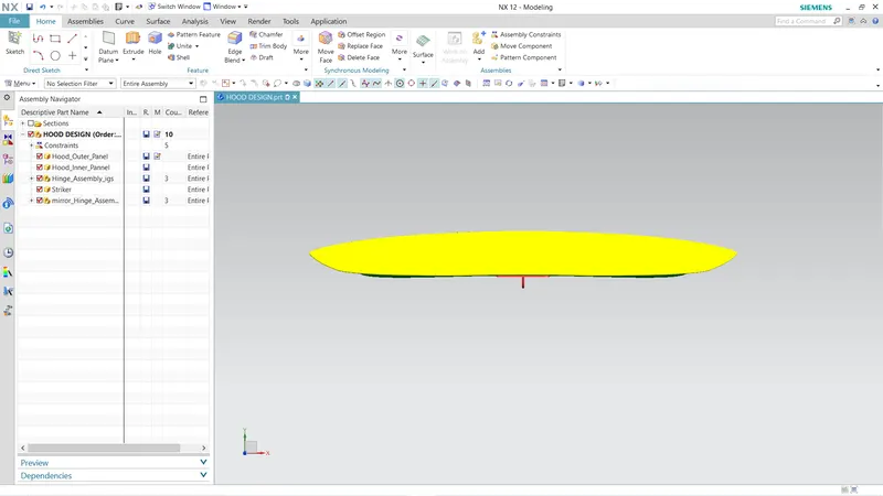
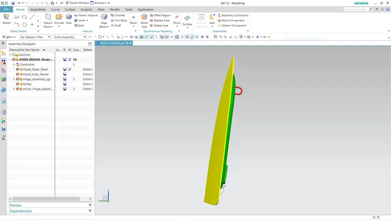
Hence keeping the EuroNCAP, DFM, and DFA requirements in mind, the above hood components were designed using the given outer panel surface and the master sketch.
- Reinforcements in the form of plates and embosses were provided to ensure safety.
- Mastic points were provided that covered a wide area of the hood that will act as an adhesive between the hood's inner and outer panel and help reduce the NVH levels inside the compartment.
- Placement of hinge and striker such that the latch closes and remains closed during travel.
- The outer panel was hemmed with the inner panel to attach them together without using fasteners or welding that would otherwise make the hood aesthetically poor.
Reference
euroNCAP protocols for engineers linkedin euroNCAP pedestrian testing protocol Journal