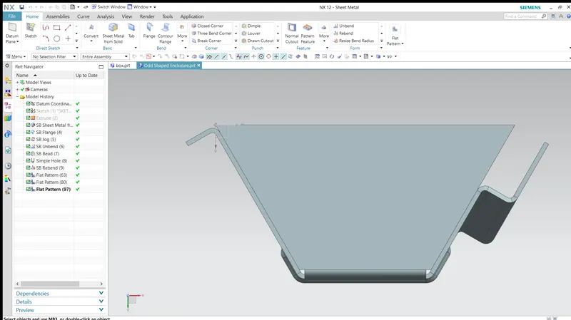
Advanced Sheet Metal Design Using NX Cad_Odd Shaped Enclosure
Objective:
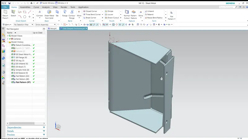
The main objective of this project is to create the odd shaped enclosure and its flat pattern in NX cad Sheet Metal Application.
Software Used :
Siemens NX 12
Introduction :
NX Sheet Metal provides a set of tools within the NX design environment that allows for simple and fast design of sheet metal parts, dependent on their material and manufacturing process. With NX Sheet Metal, formed and unformed representations of the parts are created closely following the industry workflows and best practices for bending calculations, tooling, and sheet metal features.
Sheet Metal is a metal with a small thickness ranging from 1-3 mm which is made thin and flat by rolling or hammering process. A number of mechanical components are made up of Sheet Metal. Sheet metal is widely used in the manufacturing industry due to its various advantages. In this project, sheet metal is designed in Siemens NX CAD software following the industrial approach. The use of a parametric modeling environment is the main use made in this project.
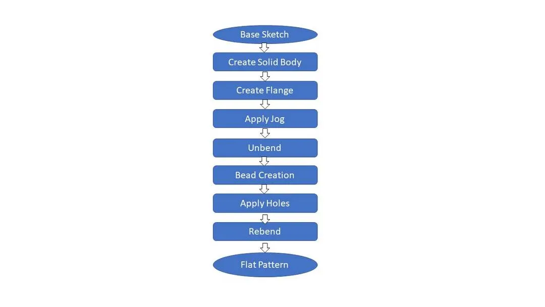
Design Methodology Flow chart :
Features Used
- Sketch: The sketch is the fundamental base element for any feature in the design of any sheet metal component. Most of the features require a sketch. The very first step is to sketch which is then used to create a tab or the base feature. So, the first sketch can be called a base sketch. For other features which are the children features of the tab, the sketch may require again on a particular plane or a face.
-
Extrude: First of all a solid model is created in the sheet metal workbench of NX CAD. The sketch profile of our solid model is created and then extrude command is used. Extrude Command is used to convert the 2D sketch into a 3D model.
-
Convert to Sheet Metal: After the creation of the solid model use the command convert to sheet metal from solid which is available in the sheet metal workbench of NX. The faces and the edges are to be selected which is to be wrapped around by a sheet metal. After wrapping the sheet metal around the solid body the solid body is hidden.
-
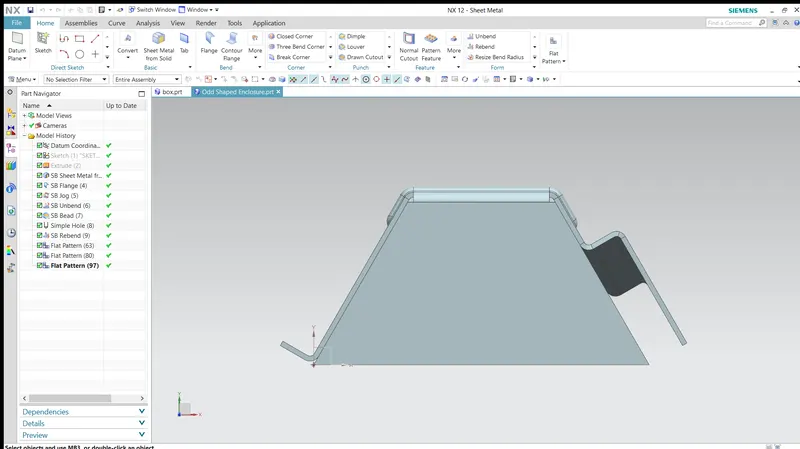
Flange: After the wrapping of sheet metal features are added like flanges and jogs. Flange is a projecting rim on a flat object. Flanges can be given to the edges of the model by using the flange command available in the sheet metal workbench. Flanges are given to the required edges.
-
Jog: This feature allows a flange or a tab to bend following a specific curve on the surface of the flange or tab and extend it to its original length. It is like lifting one side of the flange or tab from the curve. In this enclosure, a straight line inclined to the horizontal is created on the face of the inclined flange of the other side and the jog feature is applied.
-
Unbend: This is a very powerful and very useful tool in Siemens NX. It allows all the bends made by the various features to the unbent state at once. In order to achieve a flat configuration of the sheet metal as per the design intent, it is necessary to choose the bends in order. It is also possible to box select all the bends at once. Once the unbend feature is used, further features can be carried out using the sketches created in the unbent state.
-
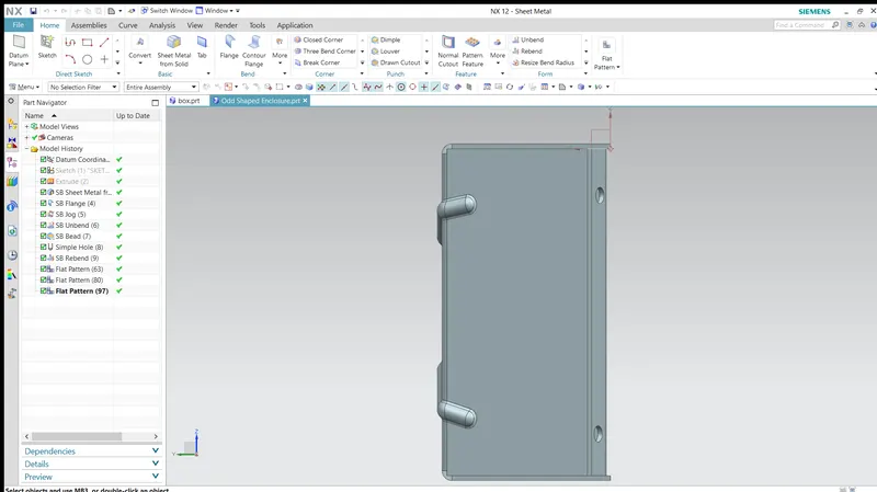
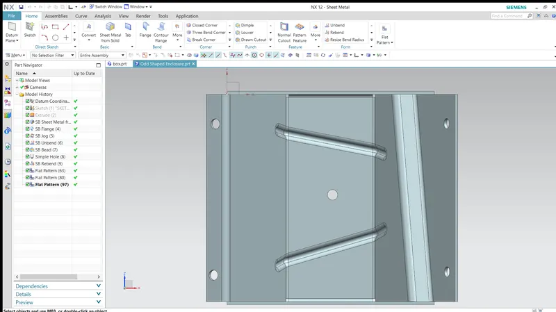
Hole: Hole feature in sheet metal design workbench is just like in the model workbench. It can create either simple or counterbore or countersink or tapped holes. For this casing, first, the four points are sketched symmetric to the x-axis in position and the hole feature is applied.
-
Beads: Beads are the features added in sheet metal components in order to increase the stiffness of the component. Beads require a sketch in order to apply the feature. It can be either an open or closed profile. For this enclosure, the first two lines are sketched on the flat surface of the top face which is inclined and is symmetrical to the horizontal line passing through the midpoint of the vertical edge of the part. The beads of 3 mm depth are then applied.
- Rebend: All the features added after the unbend feature are added in the unbend state itself. After the addition of sketches and additional features are completed, the sheet metal component has to be rebent to the required position. This is done using the rebend feature and selecting all the bends in order or by box selection. This completes the design process of the casing adding the features.
-
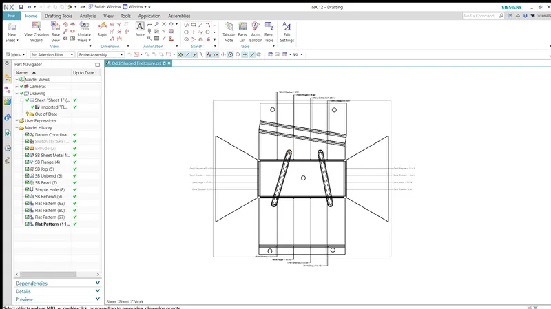
Flat Pattern: Flat pattern is the representation of the entire sheet metal component in the 2D form of the flat sheet metal with all the bends, cut-outs, holes, and additional features in the form of lines or edges. The flat pattern ensures the ability to cut the sheet metal out of the raw sheet metal plate. It removes the possible errors such as interference or collision within the same component. The flat pattern of this enclosure indicating the bend radius, bend angle, and bend direction are shown below.
Drawing Sheet Creation
Different Views