Design and Draft Analysis of Base Bracket
Objective :
- Create B-class surface, C-class surface, and the tooling axis for the given Base bracket model.
- To publish class-A surface, B-class surface, C-class surface, and the tooling axis
- Performing draft analysis to verify the creation of the Tooling axis.
Software :
- CATIA V5 (Generative Shape Design)
Introduction:
CATIA V5
CATIA is a multi platform 3D software suite developed by Dassault Systèmes, encompassing CAD, CAM as well as CAE. Dassault is a French engineering giant active in the field of aviation, 3D design, 3D digital mock-ups, and product lifecycle management (PLM) software. CATIA is a solid modeling tool that unites the 3D parametric features with 2D tools and also addresses every design-to-manufacturing process. In addition to creating solid models and assemblies, CATIA also provides generating orthographic, section, auxiliary, isometric, or detailed 2D drawing views. It is also possible to generate model dimensions and create reference dimensions in the drawing views. The bi-directionally associative property of CATIA ensures that the modifications made in the model are reflected in the drawing views and vice-versa.
Generative Shape Design
It provides an extensive set of tools for creating and modifying mechanical surfaces used in the design of complex shapes or hybrid parts. Its feature-based approach offers a productive and intuitive design environment to capture and reuse design methodologies and specifications. Help to design advanced shapes that are based on a combination of wireframe and extensive multiple surfaces. It includes high-level features with full specification capture and reuse.
A-Class Surface
A-Class surface is a term used in plastic product design. That means the surface of a component that is smooth( aesthetic) or visible side to the human eye after the part is assembled. it refers to those surfaces which are visible and abide by the physical meaning of a product.
B-Class Surface
B-Class surfaces are the secondary surfaces that you can see sometimes, but are less important, such as the inside of your glove box, ashtray, etc... These must be smooth and "error-free" as well but are not held to the standards that class A surfaces are. it also means the thickness of a part.
C-Class Surface
C-class surfaces are the backside surfaces that can have tool marks, flash, and other imperfections without hurting appearance, function, etc...it also means A and B combined to give C surface.
Draft Analysis
The Draft Analysis command enables you to detect if the part you drafted will be easily removed. This type of analysis is performed based on color ranges identifying zones on the analyzed element where the deviation from the draft direction at any point corresponds to specified values.
In the molding process the molded parts have to eject from the die so there are some issues while removing the molded parts it may get sticky with the die, or while removing chances to get damaged, so we need to set up is the draft angle this draft angle helps the molded parts to eject from the die easily. the standard of OEM for the plastic components draft angle should be in 3 degrees and if it is sheet metal component 7 degree should be the draft angle, This draft is get analyzed and ensuring the part is with proper draft angles.
OEM Rules for Features Draft Analysis
The truth is no single draft angle can be applied to all part designs. Factors like wall thickness, material selection, ejection, shrink rates, finish/texture, wall depth, and manufacturing capabilities all come into play. But fear not, some simple rules can be followed that can help.
When designing a part, apply as much draft angle as possible a general rule of thumb is 1 degree of draft per 1 inch of cavity depth, but that can change with the aforementioned factors. Try following these general guidelines:
- 0.5 degrees on all vertical faces is strongly advised.
- 1 to 2 degrees works very well in most situations.
- 3 degrees is minimum for a shutoff (metal sliding on metal).
- 3 degrees is required for light texture.
- 5 or more degrees is required for heavy texture.
Surface Design Methodology:

Draft methodology Flowchart
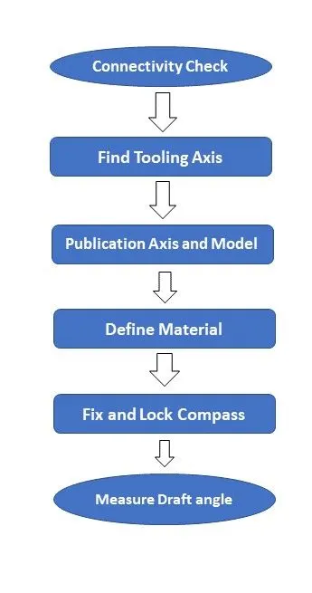
Features used for design A-Class, B-Class, and C-Class.
- Line
- Point
- Axis system
- Extrude
- untrim
- extrapolate
- Extract
- boundary
- Join
- Swept
- fillet
- close surface
- Intersecting
- publication
- Draft analysis
Procedure for design A-Class, B-Class, and C-Class of Base Bracket.
- Extract Rib then untrim, Extrapolate and trim the base bracket.
- Extract 2nd rib same as rib 1.
- offset rib 1 and rib 2 by 2.5mm.
- Extract and offset both the supportive base surface.
- Provide untrim and extrapolate and offset by 2.5mm.
- Apply Fillet and Rename as B-Class surface.
- Swept A-class Surface to the 3-degree downside with draft direction.
- Join swept and A-Class Surface then trim with B-class surface.
- Change into the close body for appropriate output.
Snapshots of Generative Shape Design Workbench
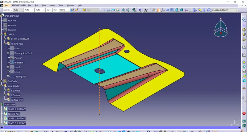
A-Class Surface with tooling axis
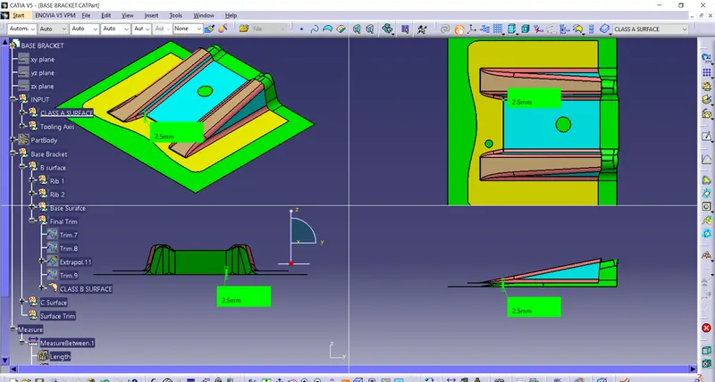
B-Class Surface with 2.5 mm offset
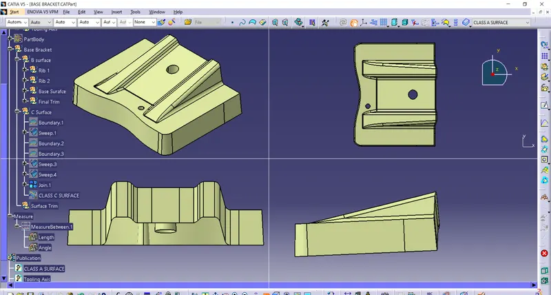
C-Class Surface without Final Trim
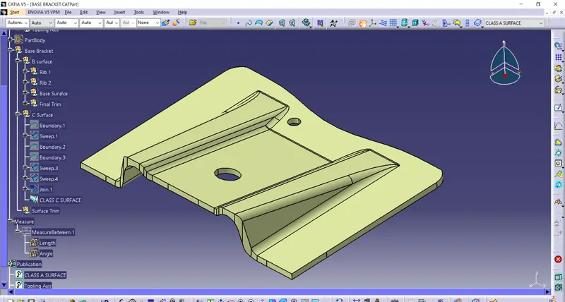
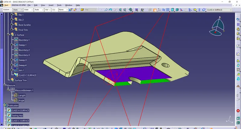
Final Output after trim C-Class with B-Class
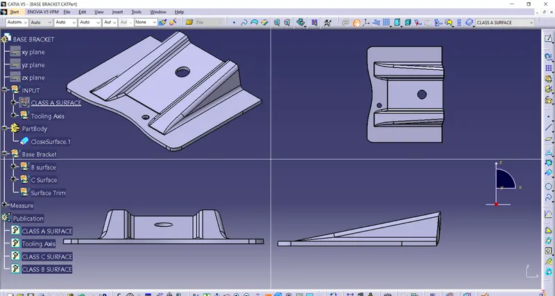
Closed Body of Base Bracket
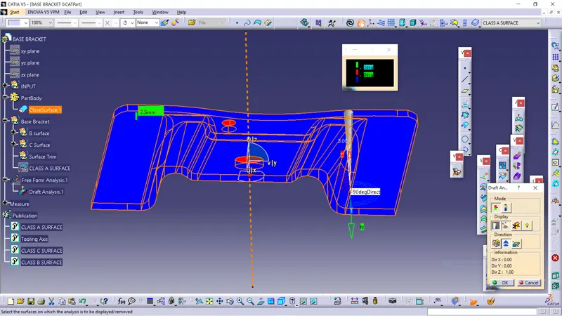
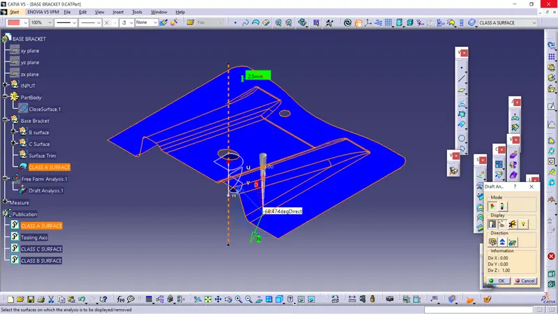
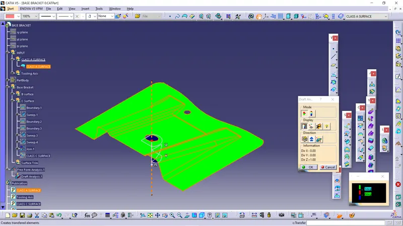
Procedure for Features Draft Analysis
- Before performing the draft analysis we create the Main tooling axis then the procedure.
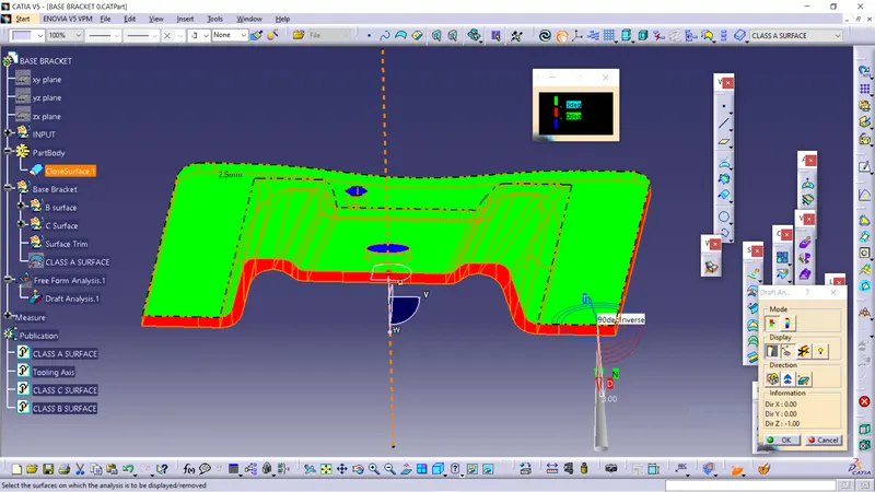
- {Go to menu bar > select insert > Analysis > Feature Draft Analysis} .
- Now, align the compass z-direction with the main tooling axis which we created in the previous steps.
- Now, open the color scale and enter the value as 3 deg.
- Now hover the cursor over the body to check if every face has an angle greater than the given angle.
- Also, if the whole body is in green color it means that the value at all the faces is greater than the provided angle.
Snapshots for Feature Draft Analysis

Conclusion
Thus the manufacturable Base bracket was successfully designed and analyzed draft angle using CATIA V5 Surface workbench.