Master Section Development of B-Pillar
Objective:
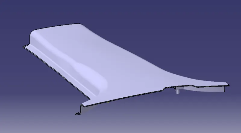
- To design and develop B-Pillar from given Class’A’ surface and master section into a functional product design, following the OEM design standards with the injection molding principles.
- The tooling axis for the given Class-A Surface should be created to meet the requirements of the draft angle.
- Perform the feature Draft analysis on B pillar and B side engineering features
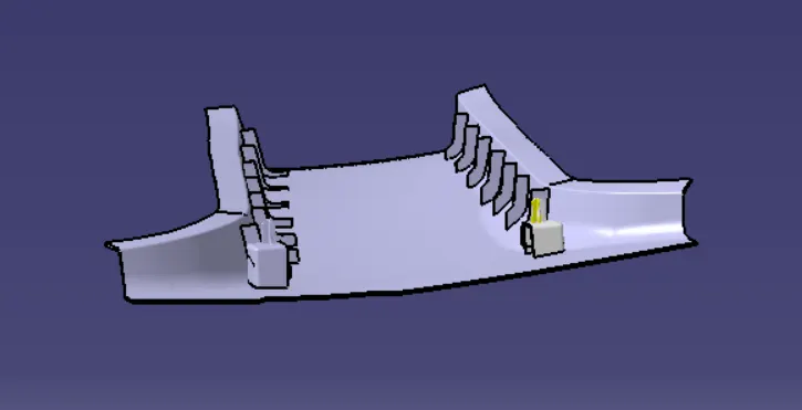
- Create the Ribs and Dog House with respect to the given Master section.
Software:
- CATIA V5 (Generative Shape Design)
Abstract:
In this project, I design a B pillar and b side features such as Dog house and ribs with respect to the master section for B pillar using the CATIA V5. I used Generative Shape Design and part design workbench and to ensure that the product is manufacturable by injection molding. I received input as Class A Surface and Master section. check and find out the master section relation and the direction to eject the tool based on the component design. Later I checked whether all faces that intersected will clear the direction based on the tooling axis. I started working on the Draft Analysis tool to check if our tooling direction clears the path for easy removal of material from the tool. After that, I go class B creation using Advance tools from the surface followed by class C creation using the sweep command. after design A B C class surface, converting close surface into solid inside the part workbench. For b side features, first design and analysis Dog house and last create Ribs and make the clearance to the door panel.
Introduction:
CATIA V5
CATIA is a multi platform 3D software suite developed by Dassault Systèmes, encompassing CAD, CAM as well as CAE. Dassault is a French engineering giant active in the field of aviation, 3D design, 3D digital mock-ups, and product lifecycle management (PLM) software. It is also possible to generate model dimensions and create reference dimensions in the drawing views. The bi-directionally associative property of CATIA ensures that the modifications made in the model are reflected in the drawing views and vice-versa.
Generative Shape Design
It provides an extensive set of tools for creating and modifying mechanical surfaces used in the design of complex shapes or hybrid parts. Its feature-based approach offers a productive and intuitive design environment to capture and reuse design methodologies and specifications. Help to design advanced shapes that are based on a combination of wireframe and extensive multiple surfaces. It includes high-level features with full specification capture and reuse.
B Pillar
B Pillar is the central pillar of the car. It is the most complex component or structure of the vehicle body. This is because the front door attaches to the B pillar and the rear door hinges to the B pillar. The B Pillar is welded to the top panel of the car and the floor panel of the car. Hence B-Pillar provides structural support to the roof.
Methodology:
- Check for any defects or irregularities in the class-A surface.
- Make a tooling axis.
- Run the draft analysis beforehand in case if there are any faces that do not have drafts, those can be corrected by the class-A designer.
- Understand the master section.
- Make the flange on both sides to make the aesthetic model complete.
- Make class-B and class-C surfaces.
- Make a close model by trimming surface A, B, and C together.
- Convert into solid the model.
- Make a B side engineering features.
- Perform draft analysis on the final model and make a report.
Procedure with Detail
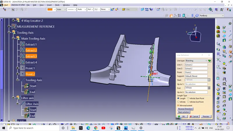
Procedure for find Tooling Axis
- A Reference Point is created along the Surface zero and a new Axis system is created.
- The X-direction and Y direction along the Class A were used to create the Tooling direction.
- Finally, the Tooling axis is created by bisecting the two lines and it is published. Class A Surface as input using surface operation commands Class B is developed.
- The tooling Axis determines the direction of Class C boundary swept with draft direction.
- When viewing from tooling direction normal all the parts that are drafted should be visible so it gives a rough idea to determine product manufacturing in Injection molding.
Flange Creation
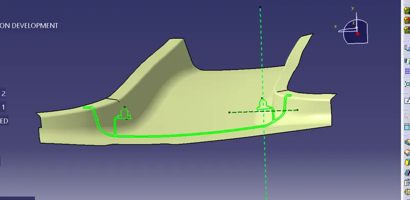
According To The Master Section, The B-Pillar Has Flanges On Both Sides. The Flanges Have To Be Included In The Design And The A And B Surface Has To Be Modified. The Surfaces Should Match The Master Section.
Procedure for Create B Class Surface
- To create a B surface, we need to offset the Class-A Surface but the Surface cannot be the same as the Class A as it would create errors while the model is sent for prototyping.
- We start with extracting the Top surface and Offset it to the thickness of the model (that is 2.5mm). Now, extract the groove parts and the base part and offset it to the same thickness.
- Now un-trim the extracted surfaces and extrapolate the surfaces such that every surface intersects with the neighboring surfaces. After completing the extrapolating, trim the surface such that the extracted surface is similar to that of the class A-surface (without fillets).
- The surface then needs to be filleted as the Class A surface with the 2.5mm added or removed by fillet radius.
- To create the Flange, the master section can be used. Extract the line on the b surface and sweep it with an angle of 90 degrees initially and create the intersection line.
- Now select the line and check for the angle and change the sweep angle similar to the master Section line and click ok.
- Join the Sweep created and the B surface and follow the same with the Class A surface.
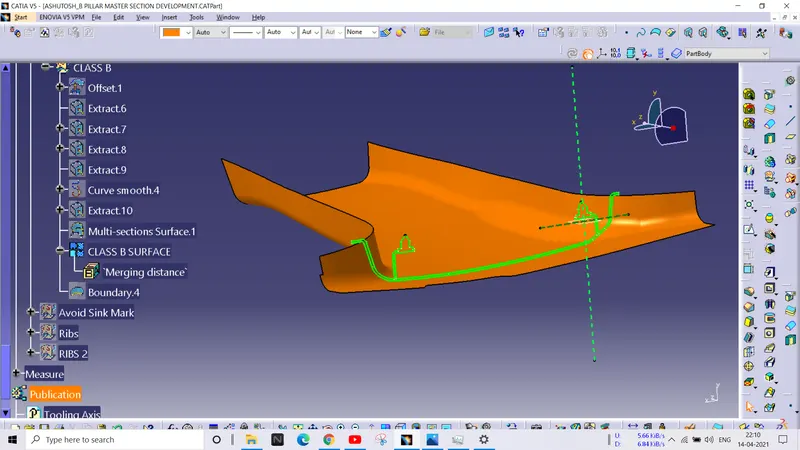
Procedure for Create C Class Surface
- After creating the B surface, the C surface needs to be created. To create the C surface, the sweep option is used.
- To create a sweep, there should be a boundary created to it. The boundary should be created separately as creating the boundary completely doesn’t create the sweep smoothly as the model contains the main unnecessary lines.
- To cover those, the smooth option is used to create the smooth surface and the Class A surface model is swept smoothly over the plane areas. Over the draft angled areas, the boundary should be created separately to create the sweep over that area.
- Now join the Class C surfaces together to create the surface.
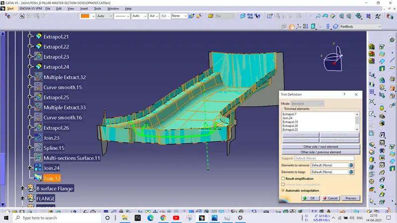
Procedure for Closed surface
- Now, start with joining the Class A and Class C surfaces together.
- Next, trim the combined surface with the Class B Surface to create the final surface.
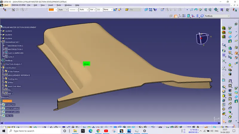
Procedure for convert into solid body
- After creating the surface, go to the Part design option and create the solid using the closed surface option.
- The solid is created.
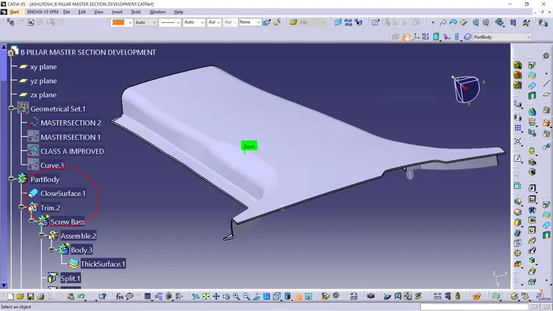
B Side Feature used in B-piller Creation
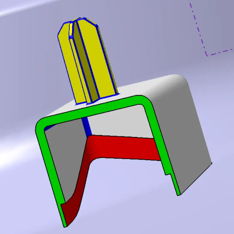
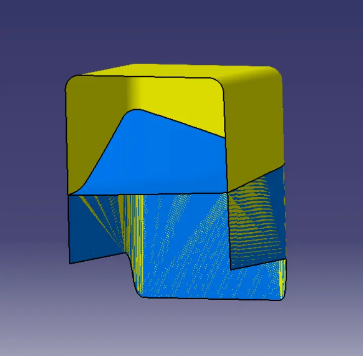
- Doghouse
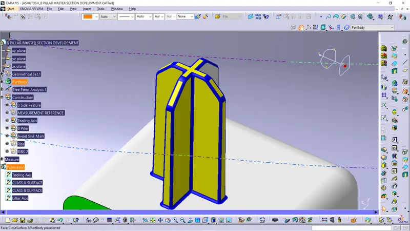
- 4 way Locator
- Ribs
Procedure for dog house creation
- To create a Doghouse, Create the sketch on the Surface face, such that there are 3 sides are created and constraint it.
- Exit the Sketcher Workbench.
- After exiting the sketcher workbench, Open the Generative Shape design and Sweep the Surfaces.
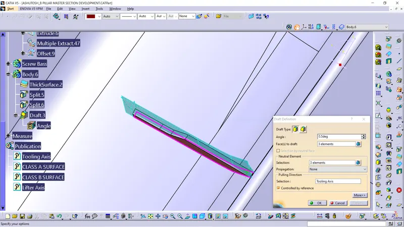
- Select the Guide Curve, the Tooling axis, and the Draft angle for the surface.
- Create a top layer as a closed body by using the Offset command. Now, join the surfaces together.
- Use Edge fillet command to give 0.25mm fillet region.
- After the Edge fillet is given use the Thickness tool in the Part body to give the thickness.
- Now to reduce the sink marks, the thickness at the merging section is reduced to 40% of the main tooling thickness.
- Now create an offset of the part to create the section.
- Trim that part with the Part body to remove the thickness.
- The Final Dog house is created.
- We can place the Locatorabove the Dog House and assemble to create the component.
Procedure for 4-Way Locator creation
- To create 4 Way locators, the ribs should be created intersecting with each other.
- Open the Sketcher Workbench and Draw 2 lines intersecting each other and constraint it by using the master section lines.
- Exit the Sketcher Workbench and Pad the Sketch with a thickness of 1 or 1.3mm.
- Chamfer the Ribs and give the Fillets to it.
Procedure for Ribs creation
- To create the Ribs, Go to the Sketcher workbench and draw a straight line on the face you want to create a rib and constraint it.
- Exit the Sketcher workbench and Open the Generative shape design and extrude the surface.
- Create a Solid component.
- Offset the Class-B surface to 5mm and split it to cut the rib surface.
- Now, union trim the rib to get the final Rib structure by removing the unnecessary faces.
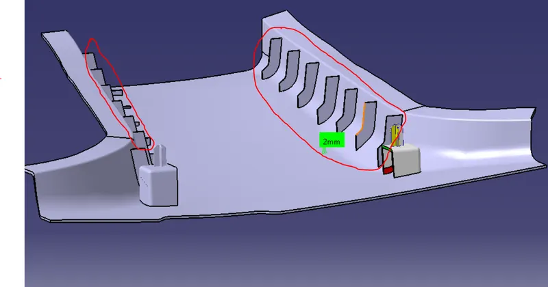
- To create the Ribs next to each other with a distance of 50mm, Go to the Class B or Class A Surface and select a line to extract.
- Select the Points repetition option to create the Points on the extracted line and give the offset distance as 50 and select the curve line.
- Now copy the Part body and paste it on the main Tree Structure(Note: Paste it with the option “Paste Special >>Paste with the Link).
- Use the Translate option to move the copied rib part body from the starting point to the ending 50mm point. Click Ok and Union trim the model.
- Follow the above steps repeatedly to create the ribs on both sides.
- The Final Solid component is created.
Feature Draft Analysis
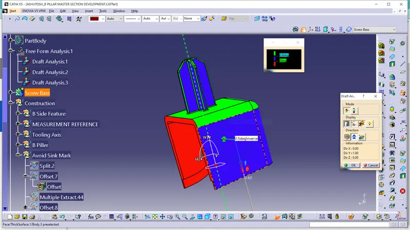
- Once model is prepared and the Tooling axis is created then the Draft analysis is done on the surface.
- To perform Draft Analysis, Go to the insert Menu >> Click Analysis >> Click Feature Draft Analysis option >> New Dialog boxes opens.
- Select the Elements as the Class-A Model and the Direction as the Tooling Axis using the Compass option to define a new direction of the draft.
- Click OK to check if all the surfaces come under the limits of 0 to 3 degrees.
- If the draft is more than 3 Degree then the surface will be shown as green.
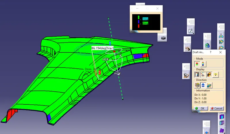
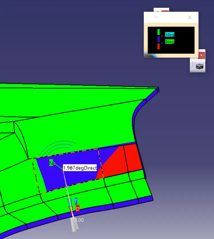
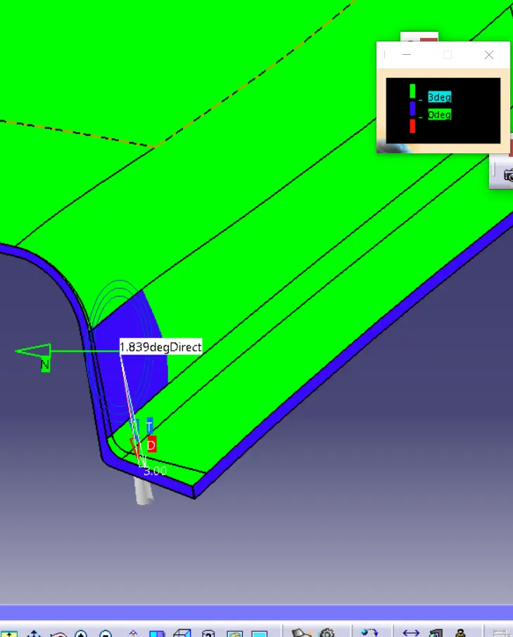
All The C Side Surfaces are are drafted and are below 2.9 degree.