Design of Door Armrest
Objective :
- To design Door armrest as per automotive OEM Standard and to ensure that the product is manufacturable by injection molding.
- Create B Class and C Class and tooling axis.
- Converting close surface into the solid inside part workbench and provide the thickness of 2.5mm.
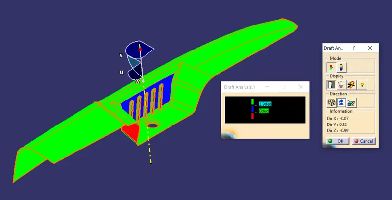
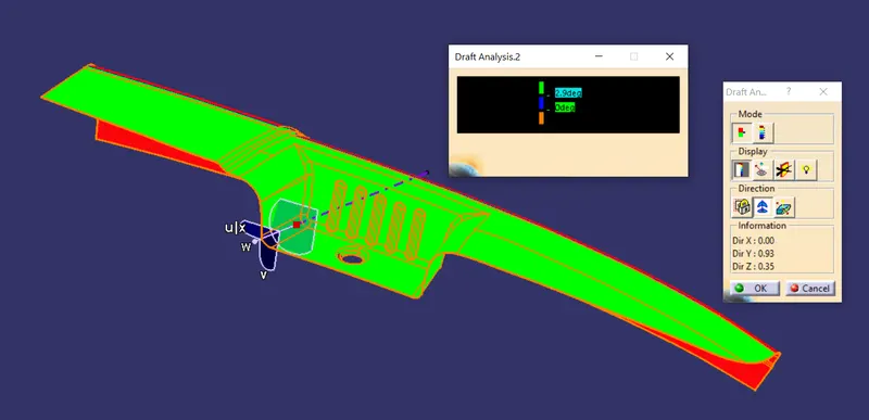
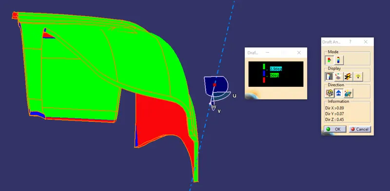
- Performing draft analysis to verify the creation of the Tooling axis and C Class surface.
Software :
- CATIA V5 (Generative Shape Design)
Abstract:
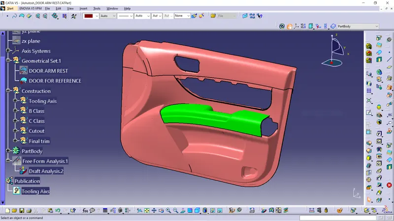
In this project, I design a door armrest using the CATIA V5 Surface workbench and to ensure that the product is manufacturable by injection molding. I received input as Class A Surface. I Check the direction to eject the tool based on the component design. Later I checked whether all faces that intersected will clear the direction based on the tooling axis. I started working on the Draft Analysis tool to check if our tooling direction clears the path for easy removal of material from the tool. After that, I go class B creation using Advance tools from the surface followed by class C creation using the sweep command. after design A B C class surface, converting close surface into solid inside the part workbench.
Procedure :
Creating tooling axis using the bisecting method:
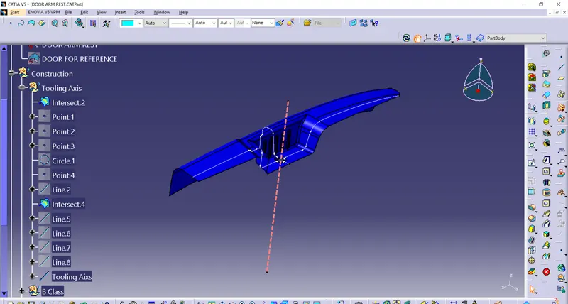
- The first thing to do is finding out the possible tooling direction by visually checking the part. Rotate the part in all direction and find out most suitable direction for tooling. Here in this case viewing from Z direction we can clear the face in tooling.
- Then we create a point on the surface of the part, we can create the point anywhere on the surface but usually we take CG point or take a point near to centre. On this point we put a new axis system.
- Then we are finding out the tooling axis in X direction. For that intersect command is used to get the boundary in X direction or XZ plane.
- Extending the drafted face using a point to point line command. Then using bisecting line command bisect both extended line to get tooling axis in X direction.
- Since in Y direction there is no wall to create bisect. We finalise the tooling axis in X direction as main tooling axis.
Creating the B CLASS Surface:
- To create a B surface, we need to offset the Class A Surface but the Surface cannot be the same as the Class A as it would create errors while the model is sent for prototyping.
- We start with extracting the Top surface and Offset it to the thickness of the model (that is 2.5mm). Now, extract the groove parts and the base part and offset it to the same thickness.
- Now un-trim the extracted surfaces and extrapolate the surfaces such that every surface intersects with the neighboring surfaces. After completing the extrapolating, trim the surface such that the extracted surface is similar to that of the class A-surface (without fillets).
- The surface then needs to be filleted as the Class A surface with the 2.5mm added or removed by fillet radius.
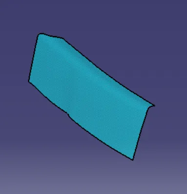
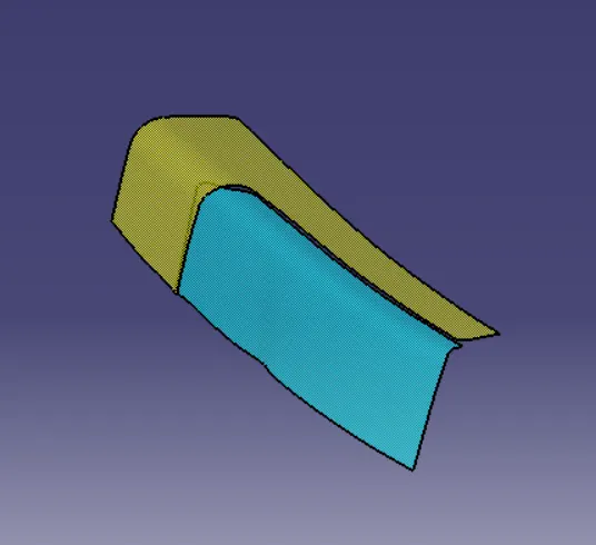
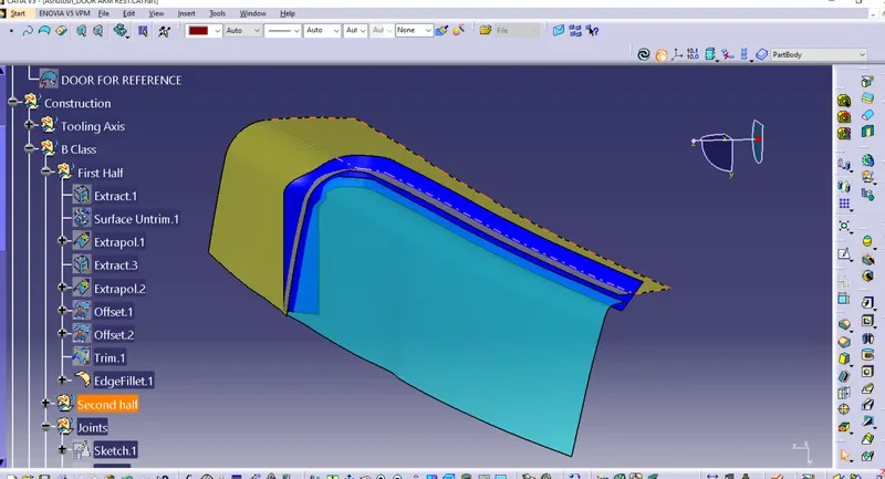
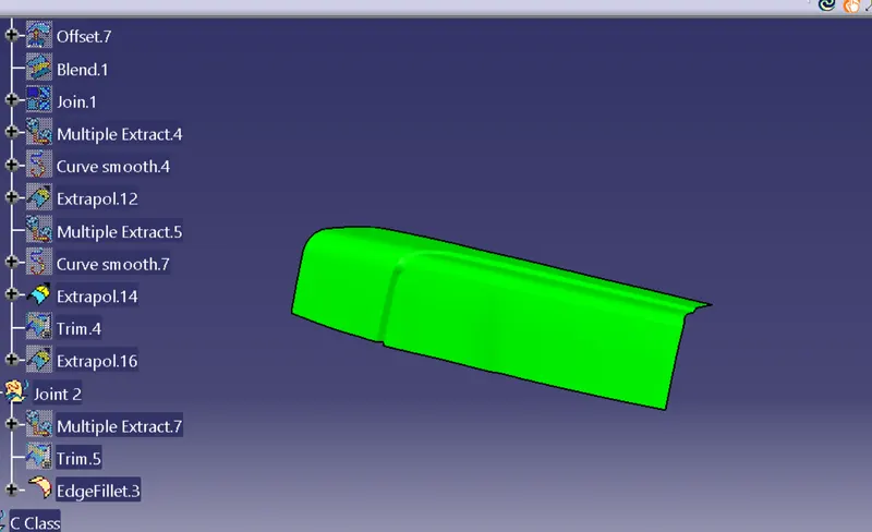
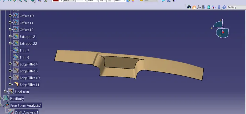
Sky Blue: First Half, Yellow: Second Half, Blue: Joiner, Green: B Surface (Plain), Brown : Final B Class Surface
Creating the C-CLASS Surface:
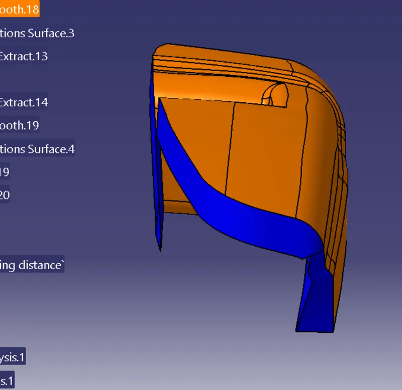
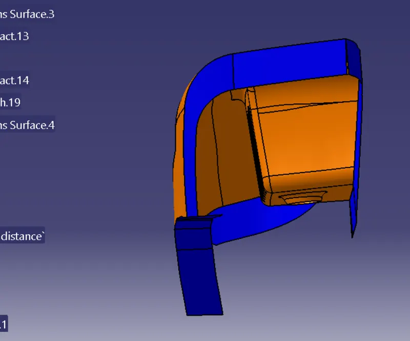
- Create a boundaries on class A surface on step by step based on staright plane and curved planes.
- creates boundaries differently divided by the angle of boudary.
- crerate sweeps on boundaries
- we will get small gap between the surfaces .its cleared using with joinig otption gap value is mantain 0.3.
- trim the sirfaces and join the classA And class b surfaces.than will get c curface.
- Than will go to part design and fill the surface.
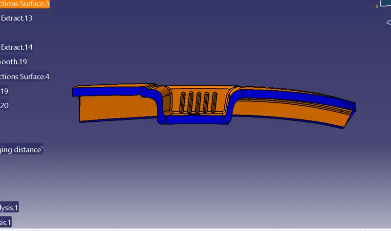
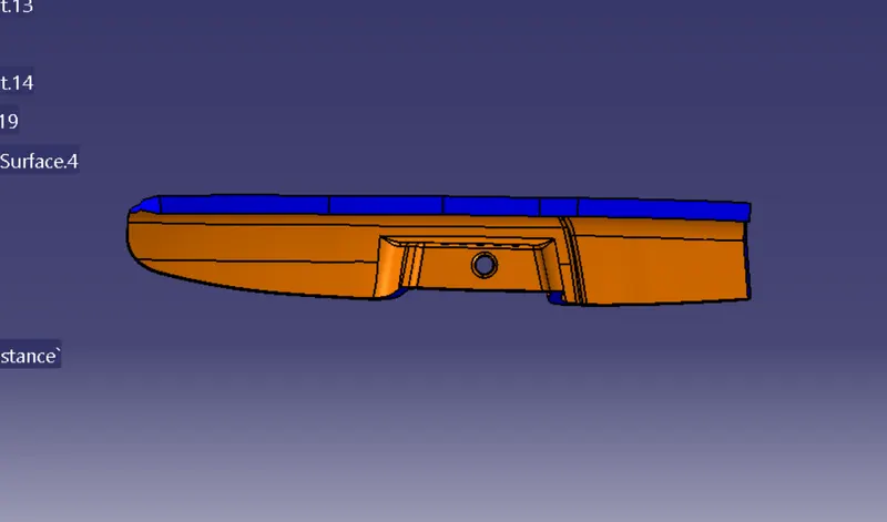
Joining or close A B C Class Surface
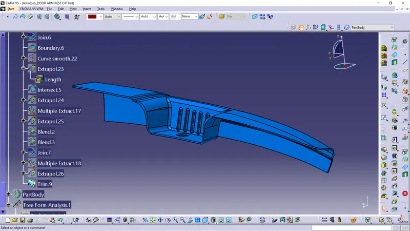
- Start with joining the Class A and Class C surfaces together.
- Next, trim the combined surface with the Class B Surface to create the final surface.
Converting into solid body
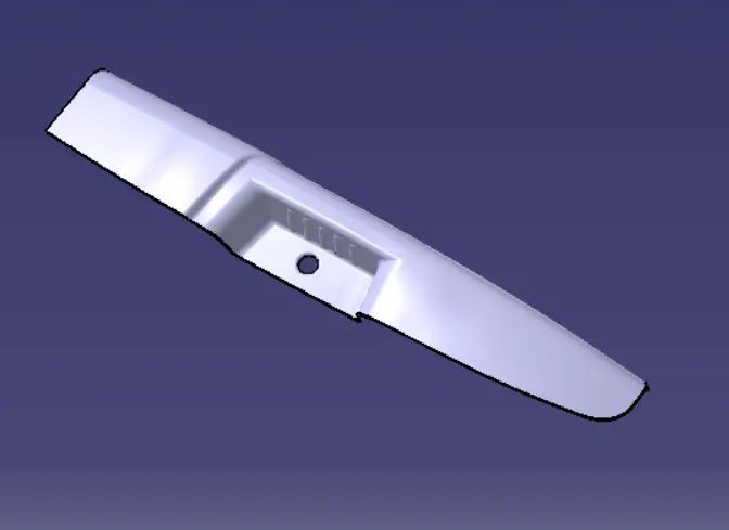
- Go to Part Design and insert a Body.
- Create a closed surface.
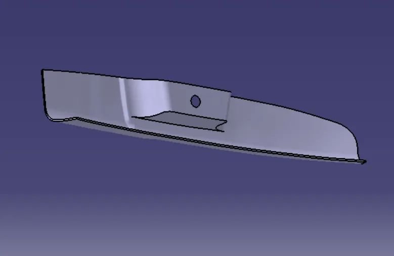
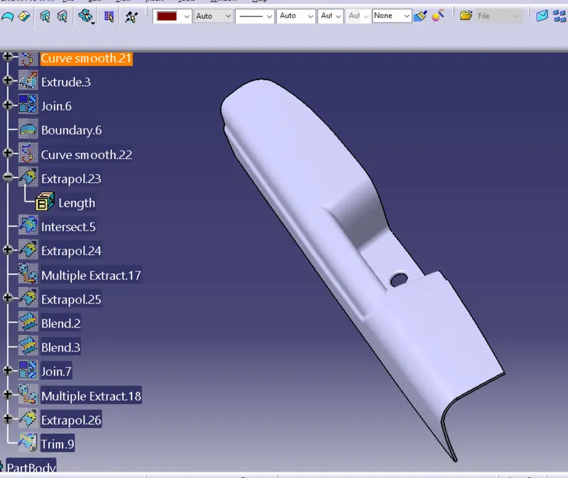
Darft Analysis :
- To perform the draft analysis the view parameters are first set to material mode.
- Then go to Insert >>analysis>>feature draft analysis.
- First, select the axis system and drag the axis system to align and coincide with the tooling axis and lock the orientation. This axis system defines the draft direction according to the tooling axis.
- Switch on the color scale and set the minimum draft value. Here it is set to 3 degrees and it will be displayed in green color. Any draft angle below 3 degrees will be shown in red color.
- Here, the compass direction is rotated to have the positive direction in maximum portion of the part. Then the compass is locked in the orientation and a new tooling axis is created using the compass as the direction.