Advanced Sheet Metal Design Using NX Cad_Sheet Metal bracket-II
Objective :
The Main aim of this project is to design sheet metal Bracket using Siemens NX Sheet Metal Application.
Software Used :
Siemens NX 12
Introduction :
NX Sheet Metal provides a set of tools within the NX design environment that allows for simple and fast design of sheet metal parts, dependent on their material and manufacturing process. With NX Sheet Metal, formed and unformed representations of the parts are created closely following the industry workflows and best practices for bending calculations, tooling, and sheet metal features.
Sheet Metal is a metal with a small thickness ranging from 1-3 mm which is made thin and flat by rolling or hammering process. A number of mechanical components are made up of Sheet Metal. Sheet metal is widely used in the manufacturing industry due to its various advantages. In this project, sheet metal is designed in Siemens NX CAD software following the industrial approach. The use of a parametric modeling environment is the main use made in this project.
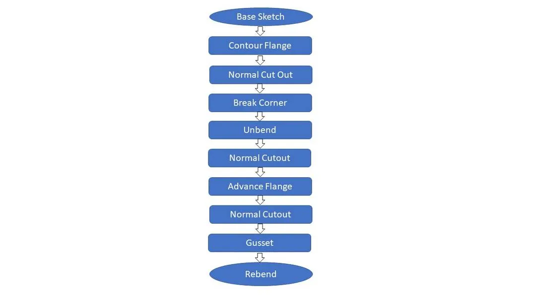
Design Methodology Flow chart :
Features Used :
- Sketch: The sketch is the fundamental base element for any feature in the design of any sheet metal component. Most of the features require a sketch. The very first step is to sketch which is then used to create a tab or the base feature. So, the first sketch can be called a base sketch. For other features which are the children features of the tab, the sketch may require again on a particular plane or a face.
-
Contour Flange: The contour flange is a flange created using the open sketch created in a plane. It is different from regular flange because it can be created in any shape and it does not require choosing the edge of any tab or existing flange. It can be at any position or at any angle. For this bracket design, a contour flange is created using the earlier sketch as the curve.
-
Normal Cut-out: A sketch is created on the XY plane to cut away the unnecessary material. Then the operation normal cut out is carried out. It cuts away the material at the right angle with respect to the sketch plane.
-
Break Corner: This feature breaks the sharp edges in the corners and makes it round or adds chamfer. It is like the fillet feature in some other CAD software. It prevents the fracture breaking of the sharp corners.
-
Unbend: This is a very powerful and very useful tool in Siemens NX. It allows all the bends made by the various features to the unbent state at once. In order to achieve a flat configuration of the sheet metal as per the design intent, it is necessary to choose the bends in order. It is also possible to box select all the bends at once. Once the unbend feature is used, further features can be carried out using the sketches created in the unbent state.
-
Rebend: All the features added after the unbend feature are added in the unbend state itself. After the addition of sketches and additional features are completed, the sheet metal component has to be rebent to the required position. This is done using the rebend feature and selecting all the bends in order or by box selection. This completes the design process of the casing adding the features.
-
Advanced Flange: Unlike base simple base flange, the advanced flange can create flange from any edge which can be either curved or straight line, open or closed profile. This allows creating a flange with a match face also. For this bracket, the advanced flange is created at the upper portion with proper parameters as shown.
-
Gussets: Gussets are basically supporting features that provide the structure of the part of the product form the base tab or flange wherever the bend exists. These are stiffening features applied at the bends. For this bracket, four rounded gussets are applied in the bends as shown below.
-
Hole: Hole feature in sheet metal design workbench is just like in the model workbench. It can create either simple or counterbore or countersink or tapped holes. For this casing, first, the four points are sketched symmetric to the x-axis in position and the hole feature is applied.
-
Flat Pattern: Flat pattern is the representation of the entire sheet metal component in the 2D form of the flat sheet metal with all the bends, cut-outs, holes, and additional features in the form of lines or edges. The flat pattern ensures the ability to cut the sheet metal out of the raw sheet metal plate. It removes the possible errors such as interference or collision within the same component.
-
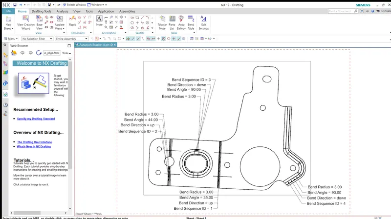
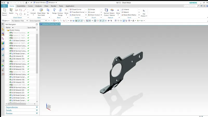
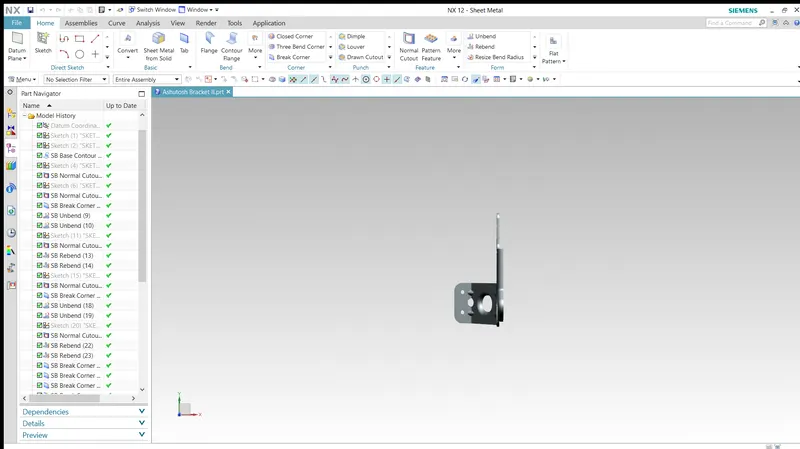
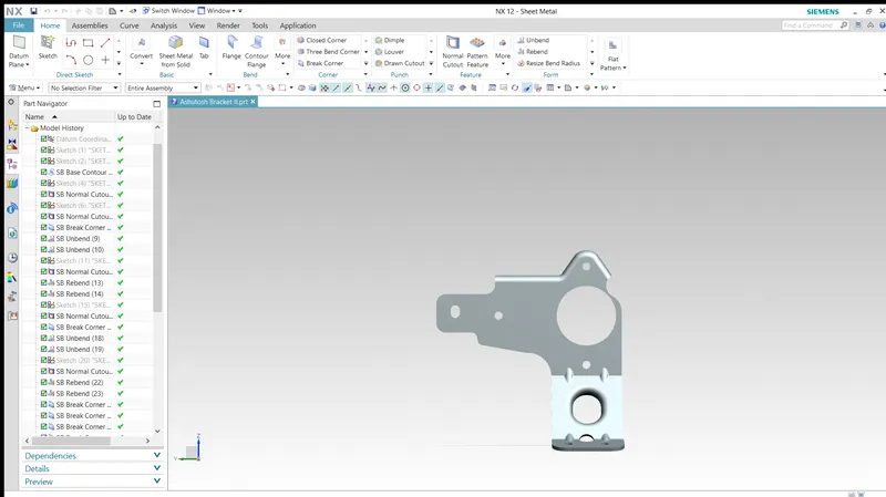
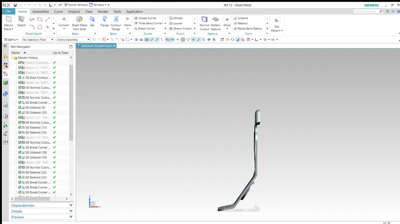
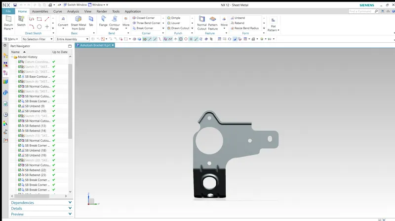
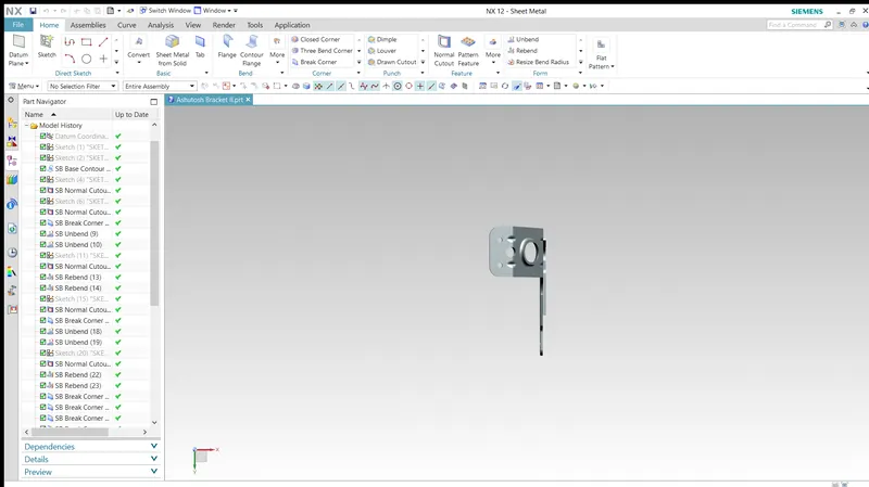
Drafting: After the design is complete, the execution or the manufacturing of the component requires a technical drawing of the component with the provided scale and with accuracy. The necessary details such as annotations, callouts, bend tables can be added as per the requirement. For this bracket design project, a drawing is created out of the flat pattern in a 2:1 scale in an A4 sheet, and an additional drawing showing different views is also shown.
Drawing Sheet
Different Views
Conclusion :
The complex bracket was designed and the drawings were successfully displayed in this project report. The model was designed and the drawings and flat pattern drawings were created using Siemens NX. We have also seen and discussed what is a neutral data file and where it is used, we have also worked on a neutral data file in Siemens NX to perform flattening and forming operations.