Fender Design Challenge
AIM:
Fender design from the Class A surface
OBJECTIVE:
The project's main objective is to design front fender of the car according to the engineering standard. And create the design of fender mounting areas.
THEORY:
What is a Fender?
Fenders are panels on a car that are located on the sides of the car in front of the doors. They serve a number of functions, not least of which is aesthetic.
One of the primary functions of a fender is to keep dirt, dust, and road debris away from the wheel and front braking system. Many have small flaps or wings that are designed to enhance this protective function. The fender will also help keep debris off of the rest of the car, which will be useful when a car throws up a rock or stick from the road.
Types of Fender
Full fender type: This type of design the fender will be covering more area around the wheel and it will be lengthy. Due to its bulky shape and more material the weight of the component increases. For reducing these concern the industry has changed to half fender type.

Half fender type: Here the fender will be covering lesser area comparing the full fender type. The fender will be limited to the back side of headlight. Most of modern day vehicles follow this design.

MANUFACTURING PROCESS:
Fender is manufactured in different stages according to the complicity of the part. Usually the stamping process included are Deep Drawing, Bending, Punching and Trimming.
Deep Drawing: Deep drawing is a sheet metal forming process in which a sheet metal blank is radially drawn into a forming die by the mechanical action of a punch.
Bending: It is a process by which metal can be deformed when applying force to the subject, which causes it to bend at an angle and form the anticipated shape, which often results in it being in a ‘V’ or a ‘U’ shape.
Punching: Punching is a machining process that involves the removal of scrap metal from a sheet of raw metal. It requires the use of a punch press to compress a tool through a sheet of raw metal.
Trimming: Trimming basically presses a part through a cutting die that runs the periphery of the work. The cutting die are precisely designed to remove the flash from a particular part.
MAIN COMMANDS USED IN NX:
- Offset curve in face: Offset curve along the face on which they lie.
- Datum plane: Create a new plane that is used to construct other features.
- Curve on surface: Creates surface spline feature directly on a face.
- Curve length: Extends or shortens a curve by a length on each end or to a total curve length.
- Intersection curve: Creates intersection curves between two sets of objects.
- Bridge curve: creates a tangent blend curve between two objects.
- Trim sheet: Trims off a portion of sheet body.
- Law extension: Creates a law-controlled extension from a base sheet, dynamically or based on laws for distance and angle.
- Emboss: Modifies a body with faces made by projection a section along the vector, with options for end cap location and shape.
- Dart: Add a dart feature along the intersection curve of two sets of faces.
- Sew: Combines sheet bodies by sewing common edges together, or combines solid bodies by sewing common faces.
- Thicken: Creates a solid body by adding thickness to a set of faces.
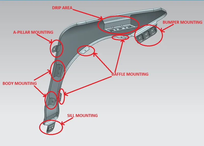
Mounting points on a fender:
- Body
- A pillar
- Sill
- Bumper
- Drip area
DRIP AREA:
For designing the drip area we have been provided with master section. So we have to follow the master section when creating the drip area.
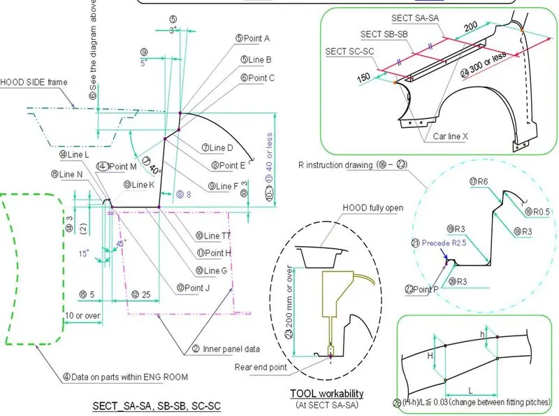
FIG: Master section of drip area
Points considered while designing the drip area:
- Drip should start from 150mm away the headlight and 300mm or less than away from the cowl area.
- The last flange of drip should be 10mm or over distance from the engine room.
- The flat flange where the holes are made should be 200mm or over distance from the hood open position. So that there is an easy tool workability.
- Create emboss and stiffeners to make the area stronger.
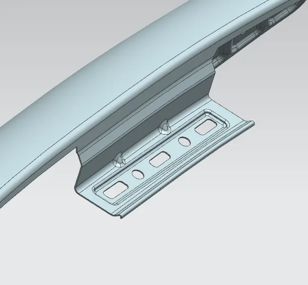
FIG: Drip area
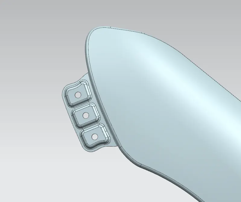
BUMPER MOUNTING:
- Created a flange with smooth curves and edges.
- Created embosses on the flange to strengthen the mounting.
- When creating embosses adjacent to one another, there should be a 2-3mm gap between them.
SILL MOUNTING:
- When creating the flange avoid sharp corners make it a smooth transition to reduce the stress around that area. For that bridge curve or curve on surface command can be used.
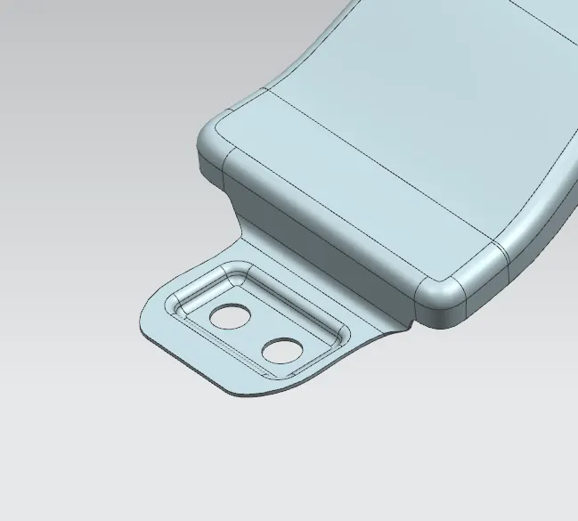
A-PILLAR MOUNTING:
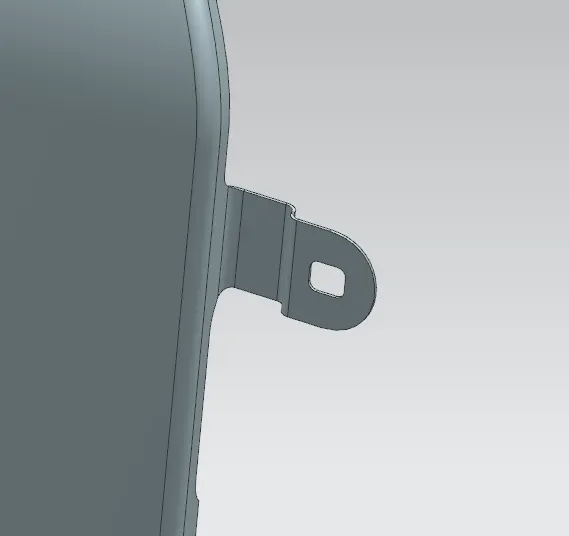
BODY:
- Here I created a slot for the tolerance and also can be used for holding the part.
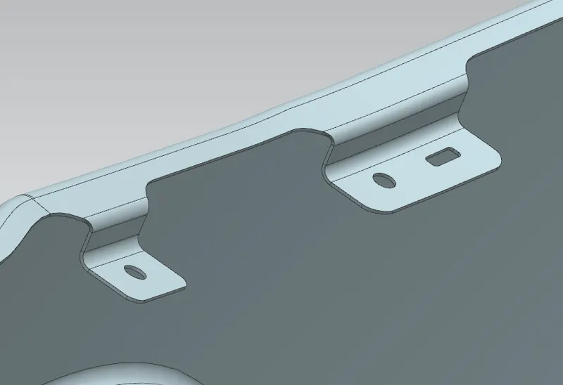
BAFFLE MOUNTING:
- These mountings are used to attach the baffle to the fender. Usually push pins are used to fix baffle to the fender.
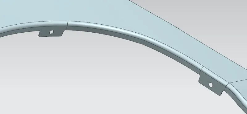
RESULT:
Fender design is completed successfully satisfying all the requirements with the given data using NX Siemens.
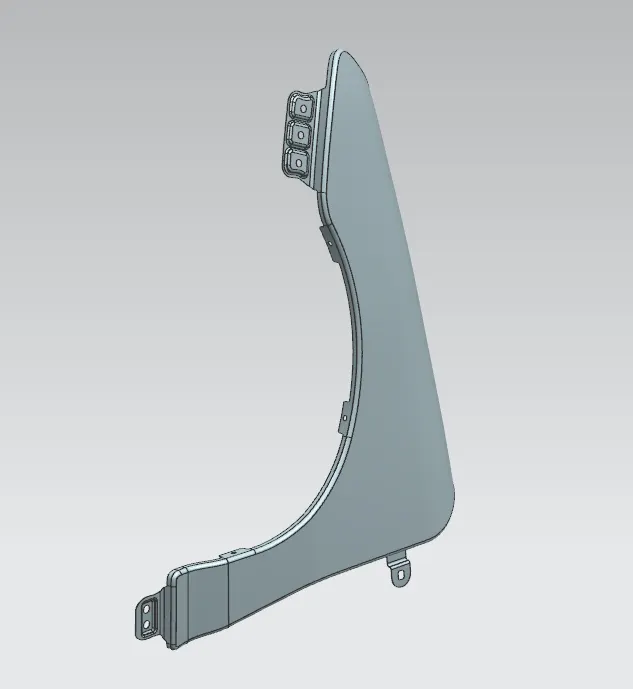
FIG: ISOMETRIC VIEW
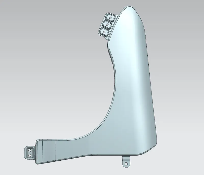
FIG: FRONT VIEW
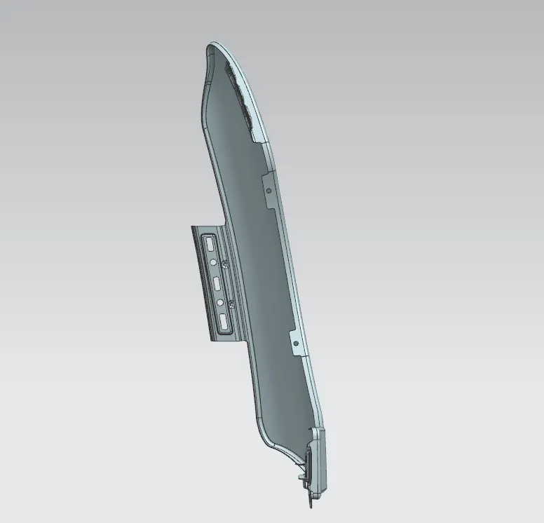
FIG: SIDE VIEW
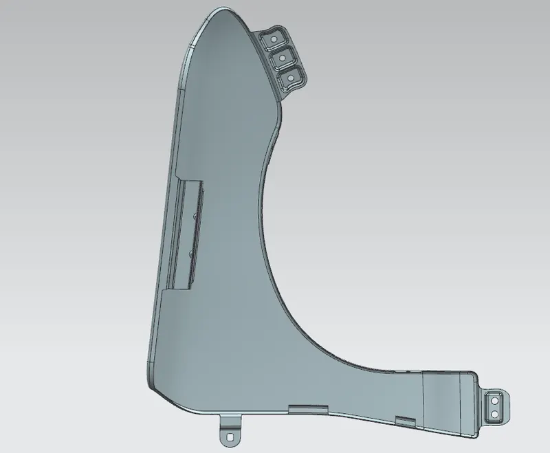
FIG: REAR VIEW