Design of Robotic Arm
Objective
The objective of this project is to design a Robotic Arm for the Pick and Place mechanism.
Introduction
- Robotic is defined as the study, design, and use of robotic systems for manufacturing. With the rise in manufacturing industrial activities, a robotic arm is invented to help various industries to perform a task or work instead of using manpower. Robots are generally used to perform unsafe, hazardous, highly repetitive, and unpleasant tasks. Robots can perform material handling, assembly, arc welding, resistance welding, machine tool load and unload function, painting, and spraying, etc. It is very useful because it possesses high precision, intelligence, and endless energy levels in doing work compared to human beings. For example, a robotic arm is widely used in assembling or packing lines by lifting small objects with a repetitive motion that humans could not bear to do in a long period of time. The light material lifting task can be done by the robotic arm efficiently and time-saving because it is not restricted by fatigue or health risks that man might experience.
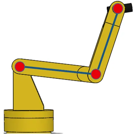
- Robots and humans share a common feature. Humans and mechanical robots—as opposite as they may seem, they, in fact, share the same underlying structure of links (bones) and joints. The basic skeleton of industrial robots, which is made up of mainly robotic arms, is a combination of links and joints. Relating it to a human body, parts that can freely bend and move about, such as the elbow and shoulder, are the joints, and the bones connecting those joints are equivalent to a robot’s links. The principle of moving joints and transmitting power through the links is common in both humans and robots.
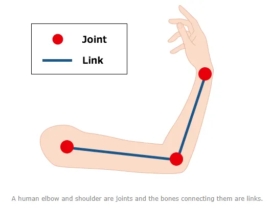
Image source - https://robotics.kawasaki.com
Robotic Arm
A robotic arm is a programmable mechanism comprising two or more segments linked by means of joints into a kinematic chain. Each joint in the chain is a servo or another motor providing either rotational or linear displacement of the segments. The number of linkages in the structure defines how many freedom degrees (DOF) it has—typically, ranging from two to the human arm maximum of seven.
Types of Robotic Arms
- Serial Link: Serial manipulators are the most common industrial robots and they are designed as a series of links connected by motor-actuated joints that extend from a base to an end-effector. Often they have an anthropomorphic arm structure described as having a "shoulder", an "elbow", and a "wrist".
- Cartesian robot/ Gantry robot: Used for pick and place work, application of sealant, assembly operations, handling machine tools, and arc welding. It's a robot whose arm has three prismatic joints, whose axes are coincident with a Cartesian coordinator.
- Cylindrical robot: Used for assembly operations, handling at machine tools, spot welding, and handling at diecasting machines. It's a robot whose axes form a cylindrical coordinate system.
- Spherical robot / Polar robot: Used for handling machine tools, spot welding, diecasting, fettling machines, gas welding, and arc welding. It's a robot whose axes form a polar coordinate system.
- SCARA robot: Used for pick and place work, application of sealant, assembly operations, and handling machine tools. This robot features two parallel rotary joints to provide compliance in a plane.
- Articulated robot: Used for assembly operations, diecasting, fettling machines, gas welding, arc welding, and spray painting. It's a robot whose arm has at least three rotary joints.
- Parallel robot: One use is a mobile platform handling cockpit flight simulators. It is a robot whose arms have concurrent prismatic or rotary joints.
- Anthropomorphic robot: It is shaped in a way that resembles a human hand, i.e. with independent fingers and thumbs.
Robot and Human motion comparison
The following figure shows a comparison between robot and human movement. The 1st to the 3rd axes are the waist and the arm, and the 4th to the 6th axes are from the wrist up to the fingertips. The first three axes carry the wrist to a specific position, and the next three axes move the wrist freely. This 6-axis construction allows robots to move freely like humans can.
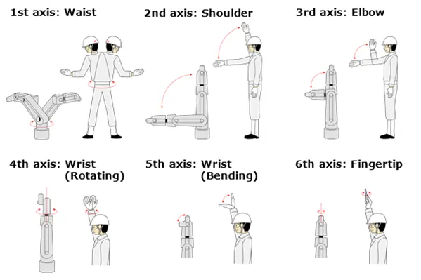
Image source - https://robotics.kawasaki.com
Material
Robots are mostly built of common materials. Some specialized robots for clean room applications, the space program, or other "high tech" projects may use titanium metal and structural composites of carbon fibers. The operating environment and strength required are major factors in material selection. There are a wide variety of metals and composites available in the market these days. The selection of material is a very deep process.
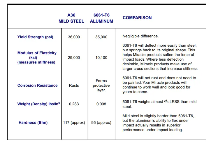
Steel, cast iron, and aluminium are the most often used materials for the arms and bases of robots. Aluminium is a softer material and therefore easy to work with. But steel is several times stronger. We chose to design the parts with aluminium. It has not been a direct selection. The shoulder has a choice to have more weight when compared to other parts. The remaining parts are not grounded and needed to carry some weight of other arms and end effector also the sheet in this case. So, they cannot be heavier than the base.
The material used for most of the parts of the robotic arm is Aluminium 6061 alloy. Aluminium 6061 is a precipitation-hardened aluminium alloy, containing magnesium and silicon as its major alloying elements. It has good mechanical properties, exhibits good weldability, and is very commonly extruded (second in popularity only to 6063). It is one of the most common alloys of aluminium for general-purpose use. The mechanical properties of 6061 depend greatly on the temperature, or heat treatment, of the material. Young's Modulus is 69 GPa (10,000 ksi). Annealed 6061 (6061-O temper) has maximum tensile strength no more than 120 MPa (18,000 psi), and maximum yield strength not more than 55 MPa (8,000 psi). The material has an elongation (stretch before ultimate failure) of 25–30%.
ABS material is also used in the end effector, which is lighter than the aluminium 6061. The main reason of using ABS instead of Aluminium 6061 is to reduce the load on the end effector. ABS (acrylonitrile-butadlene-styrene) is a low-cost engineering thermoplastic that is easily machined, fabricated and thermoformed. This thermoplastic material has excellent chemical, stress and creep resistance. ABS offers a good balance of impact, heat, chemical and abrasion resistance, dimensional stability, tensile strength, surface hardness, rigidity and electrical characteristics.
A36 Mild Steel vs 6061-T6 Aluminum
Components of Robotic Arm
1. Base
The base of the robotic arm is one of the most important part of the robotic arm, the weight of all other parts including the payload will have its great effect on this part since it is the base of this robotic arm. A servomotor is placed in the base of the robotic arm that will connect with the rotating shaft. A key is attached to the Rotating shaft that will further connect with the coupling. The first part designed in this project is the base because based on its measurements we must measure the remaining parts.
Commands Used: Sketch, Extrude, Extrude cut, Circular pattern.
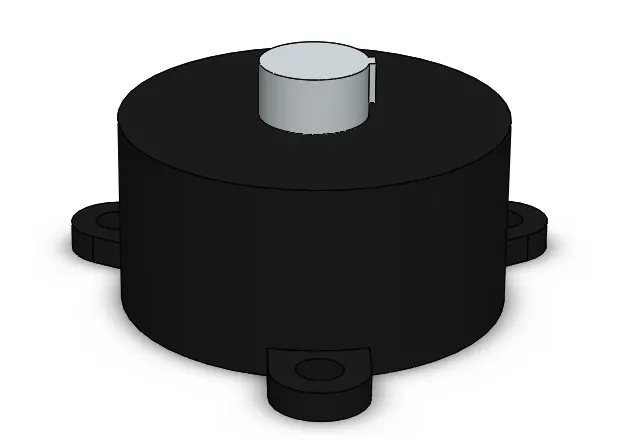
The dimensions of the shaft are given below. These values are calculated from the CAD model in Solidworks.
Length of the shaft (L) = 30 mm
Radius of the shaft (r) = 30 mm
The volume of the shaft (V) = 15476 mm cube
Mass = 0.23 kg
2. Shoulder
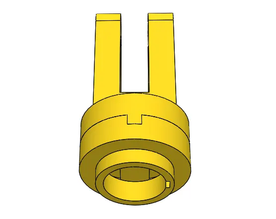
The second part of the robotic arm that I have designed is kind of an Oldham coupling which will connect with the rotating shaft and will provide rotational motion to the robotic arm. This part stays in the upper area of the base and is visible.
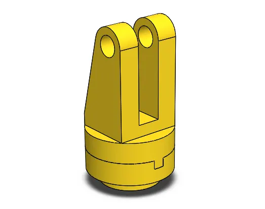
There is a combination of shaft and key attached to this part from the bottom to which a power source is connected and is made to rotate. This supposed to be the component that transfers motion (rotational) from the power source to the upper part of the body.
Commands Used: Sketch, Extrude, Extrude cut.
3. Bicep
This part can be compared to the bicep of the human arm. Like the muscle of the human arm, it moves very less when compared to the forearm but it provides the strength and holds for the forearm and wrist to do their jobs. An end of this arm is connected to the shoulder creating joint 2 and the other end is connected to the forearm of the robotic arm to create joint 3. The design of this arm is shown below. The upper end of the part is having a shaft to make itself rotate around the axis of the joint between the Shoulder and Elbow. The lower end of this part is having holes and a gap between the two extended grooves to place the wrist creating joint 3. The power source is connected to the shaft at the top end of the Elbow. The rotation of this arm happens at this end. Its assembly, creating the joint, and its limits are discussed in the assembly section. The minimum angle is given with respect to the base is 130 degrees and the maximum angle is 150 degrees. These angles are determined by the hit and trial method so that there will be no interference between all the parts of the robotic arm. The dimensions of the part are given below :
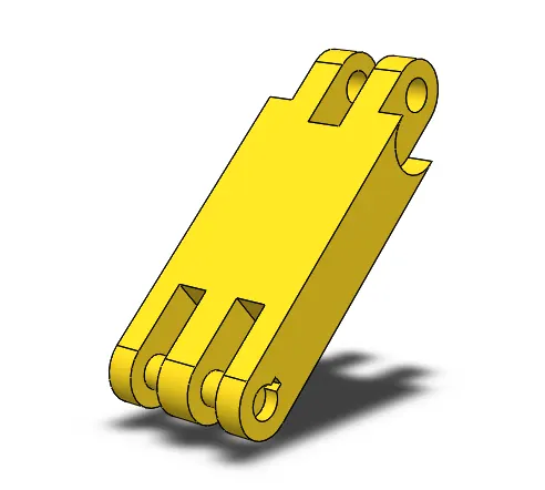
Length of the Part (L) = 150 mm
The thickness of the Part (t) = 25 mm
Width of the Part (b) = 57.4 mm
The volume of the Part (V) = 153520 meters cube
Mass = 0.414 kg
Commands Used: Sketch. Extrude, Extrude cut, Mirror Feature.
4. Forearm
This part is the forearm of this robotic arm. The reach of this robot mainly depends upon this part. The movement of this part is more when compared to the other parts. This part with the elbow creates a joint which is like the elbow in the human arm. The main purpose of these two arms is sustaining the weight that is lifted by the arm. The other end is connected to part 4 which is a kind of wrist to this hand. The power source for this arm is given to the shaft placed between the joint makes between the elbow and the forearm. The minimum angle given between this link and the previous link is 130 degrees and the maximum angle given is 160 degrees. Dimensions of this part are given below:
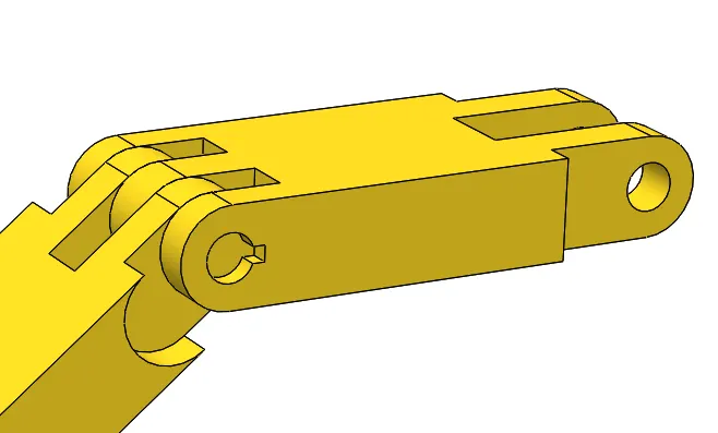
Length of the part (L) = 140 mm
The thickness of the part (t) = 25 mm
Width of the part (b) = 57.4 mm
The volume of the part (V) = 140861 mm cube
Mass of the part (M) = 0.380 kg
5. Wrist
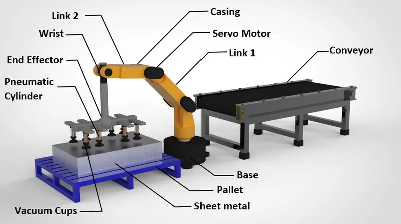
This part is the wrist of the robotic arm that acts as a linkage between the forearm and the end effector, It also holds the end effector in the desired position that we required to pick up the sheet. It can rotate 360 degrees on the axis. How much it should rotate can be adjusted as per the requirement of the user but in our case, we have constrained the rotation of the wrist because we are already getting rotational motion from the base of the robot. Dimensions of this part are given below:
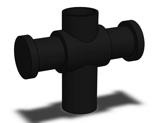
Length of the Part (L) = 68.4 mm
Height of the Part (H) = 40 mm
Volume of the Part (V) = 3896 mm cube
6. End Effector
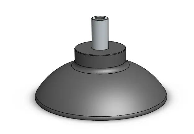
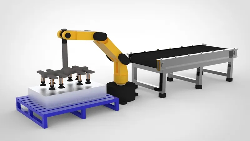
The end effector is a device or tool that is connected to the end of a robot arm where the hand would be. The end effector is the part of the robot that interacts with the environment. The structure of an end effector and the nature of the programming and hardware that drives it depends on the task the robot will be performing. The suction gripper that we are using here is SSP Vacuum Suction Spiders that are custom made for your application needs. These grippers are available in the market by a company name Schmalz. Schmalz individually designs vacuum suction spiders for your application needs. The vacuum suction spiders have been designed according to a modular principle. All versions of the vacuum suction spider are derived from the basic design which can be flexibly optimized for complex handling tasks.
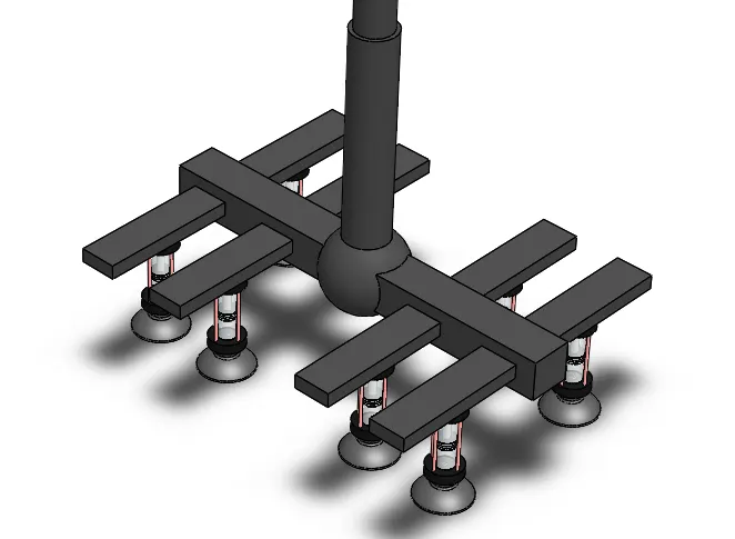
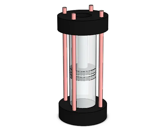
I have used a Pneumatic cylinder and vacuum cups are used as an end effector. The means of holding the sheet in this operation is executed with the help of suction cups and pneumatic cylinders. The phenomenon of this action is that; rubber suction cups get placed on the sheet. And when ready, the air between the suction cup and the sheet is sucked out, and pressure near the vacuum is created. The pressure outside the suction cup is way too larger than the pressure inside the cup. So, the air tries to enter inside the suction cup through the gap between the sheet and suction cup. This automatically creates an airlock and the sheet is strongly attached to the suction cups.
Commands Used: Sketch, Extrude, Extrude cut, Revolve, Shell, Circular pattern, Fillet.
7. Pick up Region
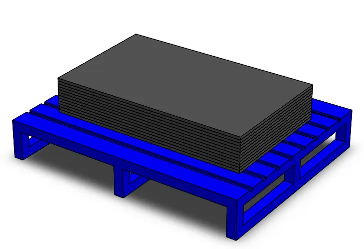
This is the predefined pick-up area, which is created to place sheet metal sheets. This predefined region should be flat so that the sheet metal sheets should be parallel to the end effector so that suction cups can easily able to pick up the sheets from this region.
8. Drop Region
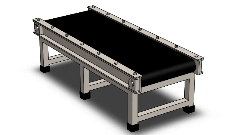
Once the sheet metal is picked up from the pick-up region, it will be drop over the conveyor. It is a predefined region where the robotic arm needs to rotate 180 degrees in order to complete this operation. This will complete the one cycle.
9. Servo Motor
A servo motor is a rotary actuator or linear actuator that allows for precise control of angular or linear position, velocity, and acceleration. It consists of a suitable motor coupled to a sensor for position feedback. It also requires a relatively sophisticated controller, often a dedicated module designed specifically for use with servomotors.
Selecting a suitable motor for the application is crucial in the design stage which a decision is made based on torque and the speed of the motor. Force calculation of joint ensures that the motor chosen can support the weight of the robotic arm and also the load which needs to be carried. Servo motors are recommended when high torque and precise speed desired by the user. For only positioning without requiring high torque, stepper motors are used in the application.
Torque is the tendency of a force to rotate an object about an axis. Mathematically, torque is defined as the cross product of the lever-arm distance and force, which tends to produce rotation i.e.
T=F*L Nm
Where,
F=force acting on the motor
L=length of the shaft
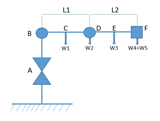
W1 = Weight of the Link 1 = 0.414 kg
W2 = Weight of the Motor = 0.25 kg
W3 = Weight of the Link 2 = 0.38 kg
W4 = Weight of the End effector = 0.1kg
W5 = Weight of the Load = 0.5 kg
L1 = Length of the Link 1 = 0.15m
L2 = Length of the Link 2 = 0.14m
Applying static equilibrium condition
Taking the sum of forces in the Y-axis
∑Fy = [(W4+W5)+ W3+W2]*g-Cy=0
= (0.6+0.38+0.025)*9.8-Cy=0
Cy = 9.849 N
∑Fy = [(W4+W5)+ W3+W2+W1]*g-By=0
= (0.6+0.38+0.025+0.414)*9.8-By=0
By = 13.90 N
Now, calculating the moments
∑Mc = -(W3*L2/2)−(W4+W5*L2)+ Mc=0
= -(0.38*0.14/2)-(0.6*0.14)+Mc=0
Mc = 0.0574 Nm
Mc = 8.12 oz/in
∑Mb = -(W4+W5)*(L1+L2)−(W3*L2/2+L1)-(W2*L1)-W1*L1/2+Mb=0
= -0.6*(0.15+0.14)-(0.38*0.14/2+0.15)-(0.025*0.15)-0.414*0.15/2+Mb=0
Mb = 0.6248 Nm
Mb = 88.47 oz/in
Based on the moment calculated, a suitable servo motor is selected.
- The base of the robotic arm will hold max load we will use a high torque servo motor based on the above calculation. For the base of the robotic arm, we will use a standard 100oz/in or 7.2kg-cm torque servo motor. It can turn 60 degrees in 15millisecond.
- At point B we will use NXM620A, 200 W (1/4 HP) Servo Motor, Rated Torque = 90 oz-in (0.637 N·m).
- At point C we will use a micro servo with 22oz/inch or 1.6kg-cm power output servo with speed and 0.12sec/60 degrees because not much torque is needed at this region.
Factor of Safety
To know the stability of the shaft we need to find the Factor of Safety of a solid shaft. We need to calculate Induced shear and allowable shear to find the Factor of Safety.
Induced Shear = `T*16/pid^3`
As we know the torque produced at the base of the robotic arm is 100oz/in = 0.7062 Nm
The diameter of the solid circular shaft (d) = 0.06m
Induced Shear = `0.7062*16/3.14*(0.06)^3`
= 16660.57 KPa
= 16.66 MPa
As we know the induced shear the allowable shear is to be taken from the ASME code depending upon the material we have considered. So, according to the ASME code for T6 6061 Aluminium material the allowable shear of the solid shaft is calculated below. The maximum shear stress should be 0.3 times tensile stress as per the ASME code.
For T6 6061 aluminium alloy the tensile = 276 MPa
For T6 6061 aluminium alloy the UTS = 310 MPa
We must take the highest value that is UTS for calculating the allowable shear as per ASME code.
Allowable shear = 0.18 * 310 = 55.8 MPa
Therefore, the factor of safety is = Allowable shear / Induced shear = 55.8 / 16.66
The Factor of safety of a solid shaft is = 3.34
ASSEMBLY
After designing all the individual parts in Solidworks, the next is to assemble all the individual parts in the assembly environment. If we describe the functionality of the robotic arm, it is 3 degrees of freedom system. 3 degrees of freedom (3DOF) refers to the freedom of movement of a rigid body in three-dimensional space. We can increase 1 degree of freedom of the robotic arm by allowing the wrist of the robotic arm to rotate but we have intentionally constrained the rotation of the wrist as we are already getting the rotation from the base of the robotic arm.
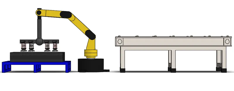
Side View
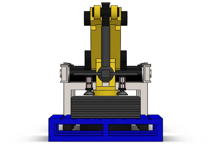
Front View
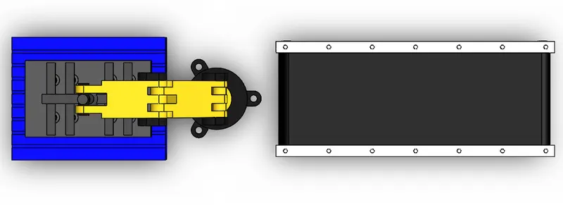
Top View
Isometric View

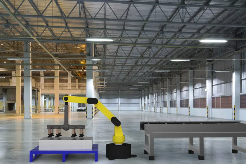
Rendering
Conclusion
- The main reason to make the choice of designing a robotic arm, firstly is the transport of the sheet from the stack to the shearing machine.
- Second, here is a space constraint we have in the industry. The stack of the sheets and the shearing machine are close to each other. They are so close that any other kind of transport such as a linear robot cannot be used.
- The robotic arm for the pick and place mechanism is successfully designed.
Future Scope
- There is always more room for innovation in any study. In a further development, the robotic arm can be situated on a mobile platform with 4 wheels to allow portability and navigation.
- This will increase the reach of the robotic arm and it can easily able to pick and place the object from one place to another.
- We can also change the type of gripper for different operations, as there are various types of end effectors available in the market.
References
[1] www.SocietyofRobots.com
[2] https://www.divaportal.org/smash/get/diva2:1068547/FULLTEXT02.pdf
[3] http://www.spu.edu.sy/downloads/files/1495967538_1111.pdf
[4] https://robotics.kawasaki.com/ja1/xyz/en/1804-03/
[5] https://rozum.com/servos-as-robot-components/
[6]https://www.researchgate.net/publication/289893486_Design_and_Development_of_a_Mechanism_of_Robotic_Arm_for_Lifting_Part1
- Viacheslav Dobrovolskiygreat job! Simple and efficient.