Design of a formula VEE Racing Car
Objective
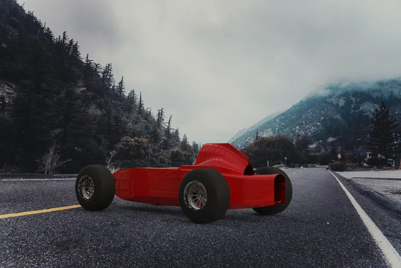
The objective of this project is to design a Formula Vee racing car.
Introduction
Formula Vee or Formula Volkswagen is a popular open wheel, single-seater junior motor racing formula, with relatively low costs in comparison to Formula Ford or Formula BMW. The class is based on a pre-1963 Volkswagen Beetle, utilizing a collection of the stock parts to form a competitive race car around a purpose-built tube frame and racing tires. The VW engine, transmission, front suspension, brakes and wheels are stock or modified stock parts. The chassis is a tube frame design and the body is fiberglass or carbon fiber. The intention of this class is for the average person to build and maintain the car.
Over the years, the rules have evolved to improve performance, lower cost, or to allow replacement of discontinued parts. A top-running Formula Vee will go 190 km/h (120 mph) and corner at about 1.6 g. It weighs a minimum of 465 kg (1,025 lb) with driver or 500 kg (1,100 lb) with the driver as raced in the Australian 1,600 cc specification.
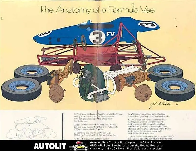
Image Source : Spencerfvee
Components of Formula Vee
1. Chassis
The purpose of the Chassis is to rigidly connect the front and rear suspension while providing attachment points for the different systems of the car. There are many different styles of chassis spaceframe, monocoque, and ladder are examples of race car frames. The most popular style for Formula Vee is the tubular space frame. Space frames are a series of tubes which are joined together to form a structure that connects all of the necessary components together. A Space frame chassis was chosen over a monocoque in spite of being heavy, as its manufacturing is cost-effective, requires simple tools and damages to the chassis can be easily rectified.
Selection of Material for Tubular Space Frame
The material which is used for chassis construction should possess the following material characteristics -
- Light Weightiness – This enables the formula car to extract maximum acceleration out of the limited engine power allowed.
- Economic Effectiveness - The material should be cheaper in cost.
- Crashworthiness- It should be capable of withstanding the loads and absorbing the corresponding energy that are likely to appear in Formula 1 cars, in order to keep the driver safe.
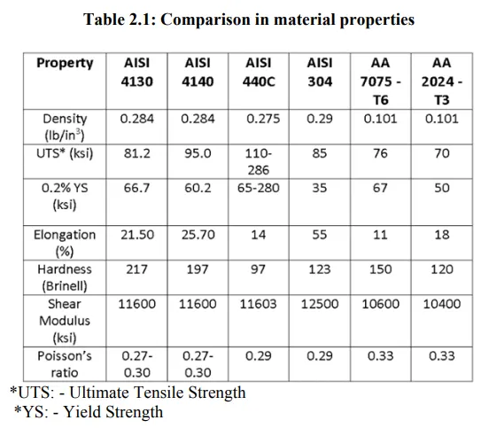
- Thus a material with the highest possible tensile strength, yield strength and shear modulus was required, which at the same time was economical and not bulky. Such a combination of properties is not possible, hence an optimization was sought. A vast variety of materials ranging from Aluminium and its alloys to steel and its alloys, which are industrially employed in the manufacture of various kinds of chassis structures were studied. Aluminium alloys and alloy steels were further studied in detail to draw a comprehensive comparison between desired properties.
- Upon comparing various alloy steels and grades of stainless steels, it was observed that stainless steels, in general, have less tensile strength and yield strength as compared to alloy steels. Next, the properties of alloy steels and Aluminium alloys were studied and compared. A broad comparison between AISI 304, AISI 4130, AISI 4140, AISI 440C, Aluminium 2024-T3 and Aluminium 7075-T6 has been shown in table. Aluminium offers the best solution to the problem of weight reduction, however it is not as rigid as steel. Also the ratio of stiffness to weight is the same for both, which implies that to attain the stiffness and rigidity offered by steel frame, an Aluminium frame must weigh the same as the steel frame. It is also more expensive as compared to steel.
Upon further comparing costs, AISI 4130 i.e. Chromoly was chosen for Chassis design because of its high hardness and optimization between yield strength, elongation, ultimate tensile strength, shear modulus, specific strength and cost. Moreover forming can be performed in annealed condition, and all the commercial welding techniques can be used to weld it. It can be forged between 9540 C-12040 C, which is a feasible temperature, hot working and cold working can be performed through conventional methods. Thus for a DFM Structure, Chromoly appears to be the best alternative.
Triangulation
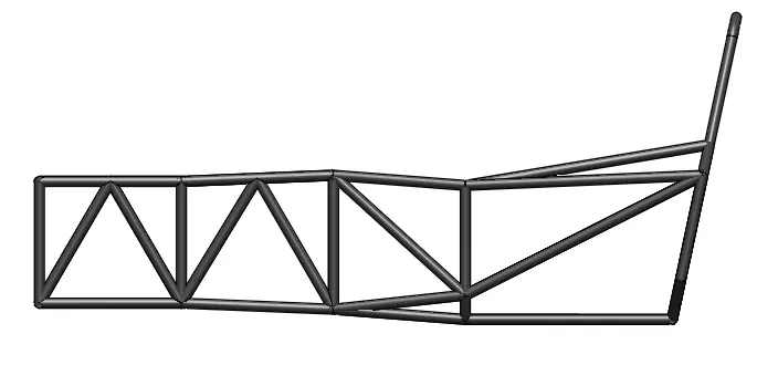
Triangulation can be used to increase the torsional stiffness of a frame, since a triangle is the simplest form which is always a structure and not a mechanism. Obviously, a frame which is a structure will be torsionally stiffer than a mechanism. Therefore, an effort should be made to triangulate the chassis as much as possible. Visualizing the frame as a collection of rods that are connected by pin joints can help frame designers locate the mechanisms in a design.
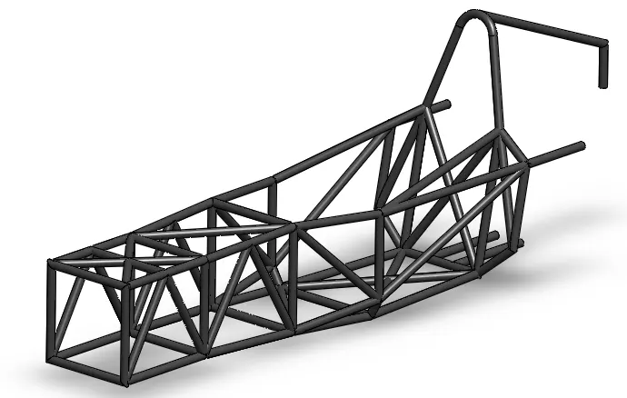
I.Type: Hollow tubular spaceframe
II.Material: Alloy Steel (AISI 4130)
III.Tube Thickness: 38 mm X 2.5 mm
IV.Weld Technique: Arc Welding
V.Software Used: Solidworks
- In order to design the chassis according to the Formula Vee regulations, I have used the weldment workbench in Solidworks Weldments functionality enables you to design a weldment structure as a single multibody part. You use 2D and 3D sketches to define the basic framework. Then you create structural members containing groups of sketch segments. You can also add items such as gussets and end caps using tools on the weldment toolbar.
- Solidworks doesn't have an existing profile of the hollow circular tube required for Formula vee regulations. So I have created manually a profile of a hollow circular tube with a thickness of 2.5mm and 38mm outer diameter and saved it into the SolidWorks directory in order to create the chassis with the required dimensions.
2. Suspension
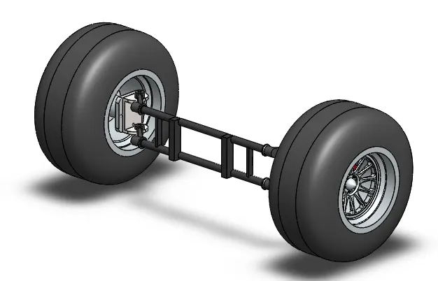
The suspension system of a vehicle refers to the group of mechanical components that connect the wheels to the frame or body. It is a system of springs, shock absorbers, and linkages that connects the vehicle to its wheels and allows relative motion between them.
The suspension assembly is made in the solid modeling environment of Solidworks and the common commands that are used are Sketch, Extrude, Extrude Cut, Offset, etc.
Type
As per the Formula Vee Regulations we can only use the suspension system of VW Beetle Type 1 which is H beam with trailing arms connecting the wheels.
The front VW beam is of a trailing link design that utilises two longitudinal links to support the steering ball joints. The wheels are effectively pulled over bumps – the links are in tension when the wheel encounters a resistance. The advantage of utilising a trailing link design is that the system is fairly compact (especially if torsion bar springs are used) and can provide a good ride for road cars. However, when subjected to lateral cornering forces, the arms tend to bend so must be made strong to resist these forces. The camber of the tyres also changes as the vehicle rolls in cornering, reducing adhesion as the outer wheel tends to go into positive camber that is directly proportional to the amout of roll. Trailing link suspensions have an infinitely long swing arm length and a roll centre at ground level.
3. Engine
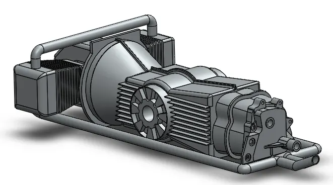
It Formula Vee engines in the UK are based around the 1300cc air-cooled engine used in the VW Beetle.
There are strict regulations around the makeup of the engine and it’s components but most of it remains standard. So you cannot modify engine components until specified.
The gearbox used within the UK series is also standard, using the original ratios and internals and are fairly easy to service and look after.
Designing a CAD model of the engine was one of the complicated and difficult part of the Formula vee car. The engine is designed predominantly using solid modeling techniques. I started designing the engine from the rear end of the exhaust pipe and moving towards the cylinder block of the engine. Most of the commands that I have used to create the engine are 2D Sketching, 3D Sketching, Extrude, Extrude cut, Sweep, Linear Pattern, Circular Pattern, Mirror, etc
According to the rule book
1. The engine shall be naturally aspirated, shall have a nominal capacity of 1300cc, shall be the GY or AGY range as fitted in the VW Citi Golf or Polo and shall have the following dimensions: Bore: 76,5mm with a tolerance of – 0.005mm and + 0.2554mm Stroke: 77,4mm.
2. Engine components shall be assembled in the standard configuration and shall comply in all respects with the VW AGY or GY specifications except for the modifications listed below. Unless otherwise stated, all tolerances or nominal dimensions listed in Section 16 will be in accordance with Volkswagen works specification.
3. Components may not be strengthened, reinforced or hardened either structurally or by any type of treatment which inherently increases their strength or hardness other than as specified.
4. Pedal Box Assembly
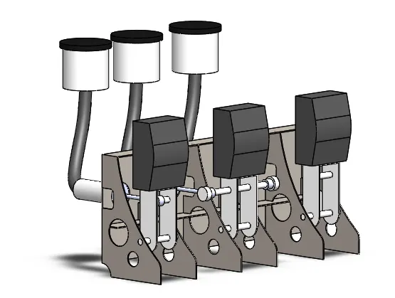
1. Pedal box contains three pedals, first one is the clutch , middle one is the brakes and 3rd one is the throttle.
2. Clutch simply pushes the master cylinder which actuates the clutch slave cylinder which will further push against a fork or lever to disengage the clutch.
3. Brake pedal is little more complex, it has to push two master cylinders, one for the front brake and second for the rear brake.
4. Throttle pedal simply connects to a cable that simply runs through the car to the carburetor on the engine.
5. Pedals and master cylinders are mounted to a very rigid removable base which is mounted by multiple bolts rigidly into the chassis.
The first thing I designed in the pedal box assembly is the pedal box housing for the clutch, brake, and throttle. Cutouts are given between them for the cables and mounting purpose with the chassis. The next thing I designed was a piston along with master cylinders which will be fixed on the chassis.
5. Wheels & Brakes
As per the Formula Vee rules and regulations :
1. Wheels shall be 14-inch diameter with a maximum rim width of 6-inch and a minimum mass of 5kg.
2. Wheels may be either pressed steel or aluminium alloys. No machining is permitted for the
purpose of removing weight.
3. The braking system shall consist of a double circuit, one controlling the front wheels and the other controlling the back wheels, operated by a single pedal.
4. Disc brakes shall be utilized on all four wheels.
5. SCCA has designated Hoosier Racing Tire as the exclusive race tire supplier for its Formula Vee class for the 2019-21 seasons for all club events.
Commands Used: Revolve, Revolve cut, Extrude, Extrude Cut, Circular Pattern, Fillet, etc.
Wheelbase
Wheelbase is the distance from the centre of front wheel to centre of rear wheel (with front wheels in the straight-ahead position). The maximum and minimum wheel base should be 2480mm and 2070mm.
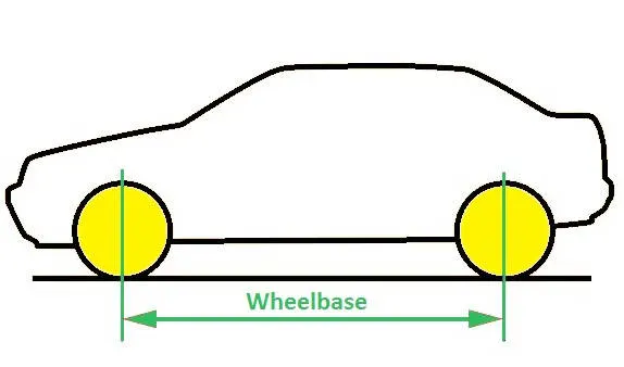
Image Source: Google
6. Body
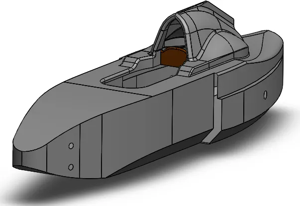
1. Body work is one of the most important component of the car that will affects the over all efficiency of the car in racing.
2. Narrow shape at the front and smooth curves are given to the body to decrease the drag force.
3. Height of the body is kept minimum for low centre of gravity.
4. Air flow paths are created at the each sides so that enough air goes to the engine for air cooling.
5. Fiberglass is used to create the body of the car as it is light weight, cheaper and offers great strength and anti corrosive properties.
The design approach I took to create the body is to create the half geometry first then, later on, mirror it.
As per regulations
The shape and design of the bodywork is unrestricted but shall incorporate the following
requirements:
i. It shall encase the frame on all four sides from a plane ahead of the front suspension to the fire -wall,
except for the driving compartment which shall be open at the top
ii. It shall also provide cover for the engine and transmission from the fire-wall to at least the centre line
of the rear axle tubes;
iii. It shall be constructed of metal, fibre-glass or other material acceptable to the FVA.
iv. Specifically, kevlar or carbon fibre bodywork components are not permitted
v. Air ducting may be attached to or incorporated in the bodywork.
vi. No ground effect or downforce-enhancing front or rear aerofoil wings will be permitted.
vii. Minimum cockpit width opening 45cms.
7. Fuel Tank
1. Fuel tank is used to carry the fuel and in most of the Formula Vee, the fuel tank is placed behind and below the drivers back forming the seat for the back.
2. This placement of fuel tank has an advantage that’s right where the car centre of gravity is, that means car balance will not shift much when taking sharp turns.
3. When the car is moving at, a large volume of fuel will put stress on the walls of the fuel tank which will cause fuel surge and unbalancing in the car.
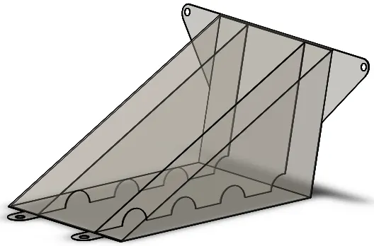
4. To fix this problem baffle plates are used which also provide internal bracing to the fuel tank which will allow drivers to be used as a backrest.
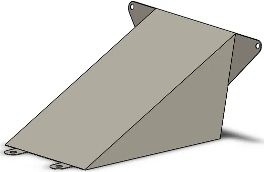
The design approach I took to design the fuel tank is pretty simple. The first thing I have created is a triangular shape solid body by using extrude command, then shell command is used to create a hollow body with a uniform thickness of 3mm. The offset command is used to create the baffle plates and cutouts are appplied.
Assembly
Standard Views
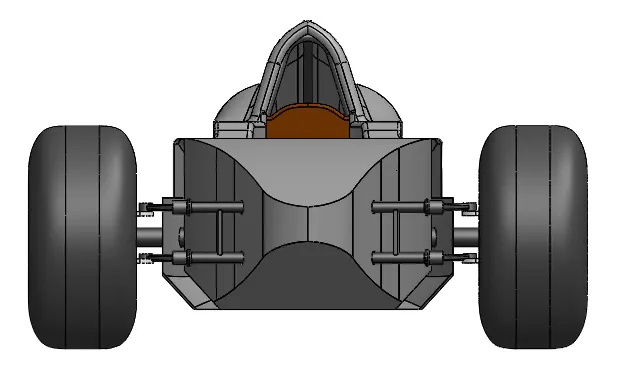
1. Front
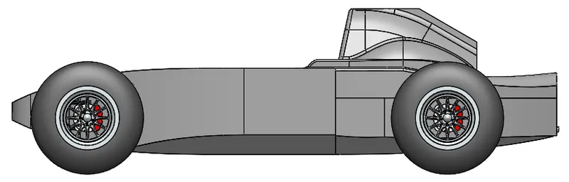
2. Side View
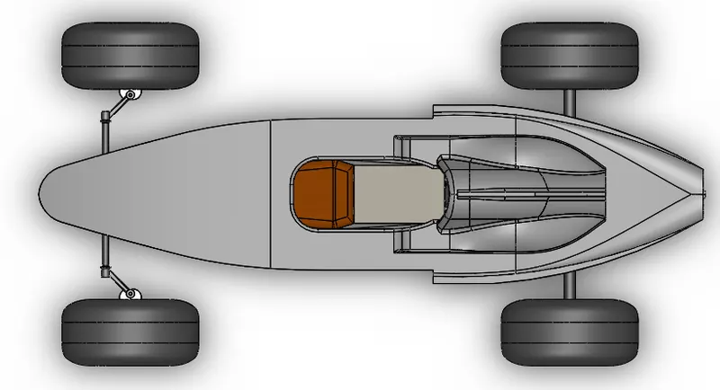
3. Top View
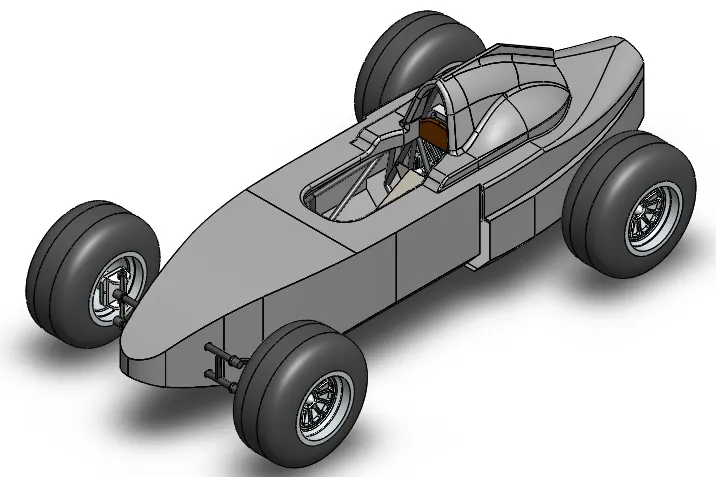
4. Isometric View
Rendering
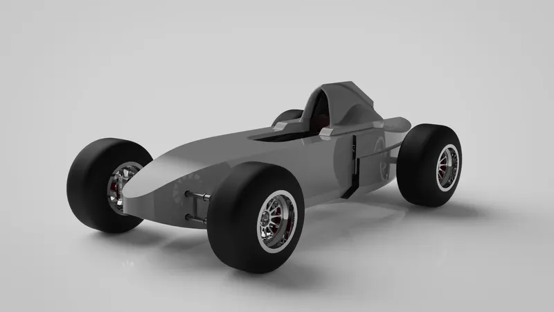
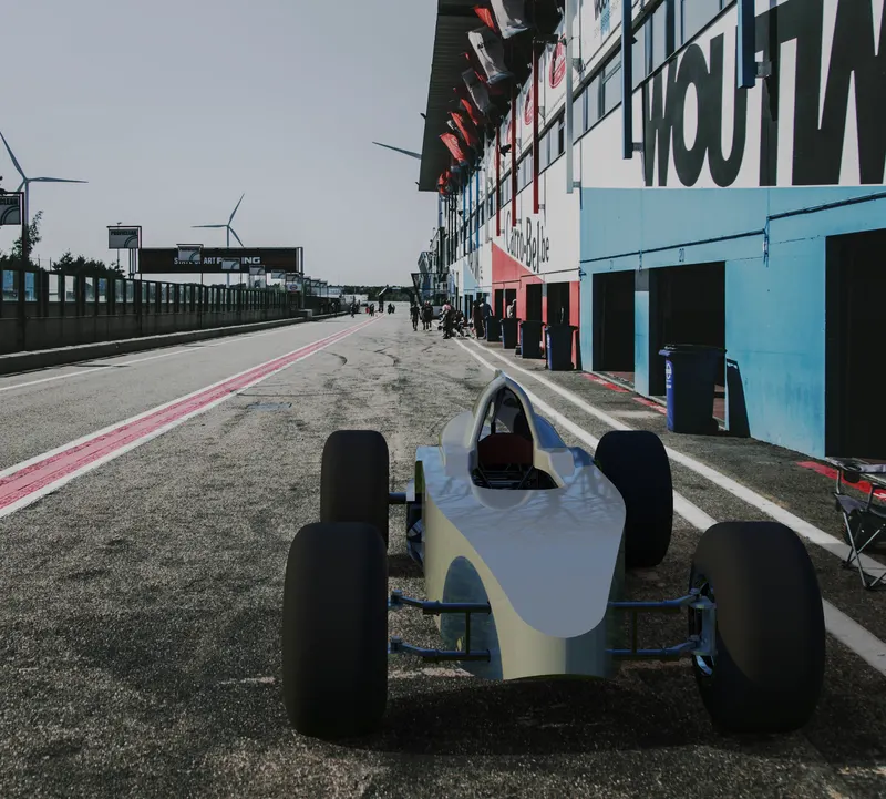
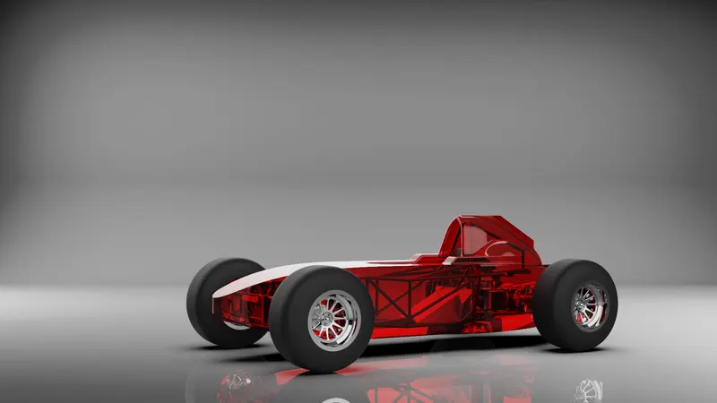
Conclusion
Successfully designed the Formula Vee racing car from a scratch for the Formula Vee racing car competition as per 2020 rules & regulations.
References
[1] https://www.750mc.co.uk/ugc-1/1/1/0/6e813dea-83f2-4f9e-8865-7e5b3b29a130.pdf
[2] https://eolstoragewe.blob.core.windows.net/wm-553616-cmsimages/2020MSANationalFormulaVeeChampionshipRegulationsV3(162064).pdf
[3] https://www.youtube.com/watch?v=nN_00HcEPls
[4] https://www.youtube.com/channel/UCj1P9eBlPZKyT2k9pFEMBjA/videos