Design of backdoor
DESIGN OF BACK DOOR/TAIL GATE(BIW)
Objective:
To design and assemble the back door (BIW) components along with its respective mounting reinforcements(Hinge mountings, Gas stay mountings, Wiper mounting, Striker mounting) from the given back door class A styling surface of satisfying all the manufacturing requiremets and functional requirements.
Software Used:
NX-CAD
Introduction:
Back door/Tail gate is the rear side door of the vehicle which is located next to passenger rear seats that covers the luggage compartment and that is opened or closed with certain angle for loading and unloading the luggage from boot space.It is operated or lifted with the help of gas stays(Pneumatic mechanism) instead of any manual support rods because the back doors are tends to be more in weight that cannot lifted off by manually.So that gas stays are used, because they are driven with electric motor which reduces the effort to lifting.Generally the back doors are made out of steel or aluminium based on the material standards or as per customer needs or requirements.The shape and design of the back door is complex in nature because it will satisfy the many manufactural and functional requirements.They serve as a great deal of purpose in protecting the passengers from the rear side collision and also responsible for the dissipating the forces towards outside during rear collisions or crashes.
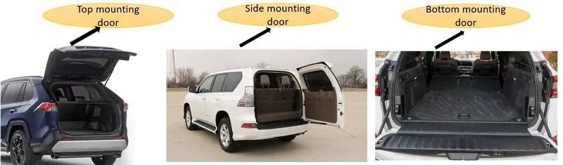
Back doors/Tail gates are postioned or designed either top side opening, bottom side opening or side opening etc; based on the structure of the car.The top opening back door provide the greater rear visibility.The side opening door are more covenient for goods handling and easier to load or unload the items from luggage compartment.
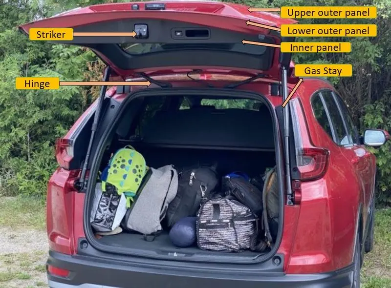
Parts of Back door/Tail gate-
- Upper and Lower outer panel
- Inner panel
- Hinges mounting reinforcements
- Gas stays mounting reinforcements
- Wiper reinforcement
- Striker reinforcement
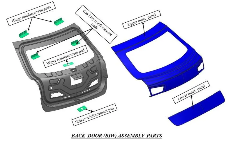
Upper and lower outer panels are the styling surface panels of the back door which gives a aesthetic look from the rear side of the vehicle.These parts are attached to the inner panel by hemming at around the edges and application of mastic sealant.Each mastic sealant can cover 80mm area in diameter.Both these panels are joined by the wleding process little inside without changing its aesthetic visuals.
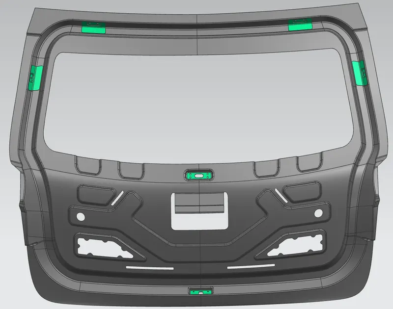
Inner panel is the strengthening component which holds by the outer panel by hemming and mastic sealant within inside.It is provided with various embossess which keeps the additional strength to the door and it is designed in such a way to distrubute all the entering forces coming inside to the outwards.All the mounting components like hinges,gas stay mountings,wiper motor,striker are mounted with the inner panel at their respective positions.Also the embosses are provided on the inner panel facing towards the tooling drection will easily reduces the impact forces during any rear collision or crashes.
While the hinges are used for opening or closing the door that is connected with the rear roof rail.Gas stay mountings are used to holds the gas stay rods and wiper mounting are used to holds the wiper rod.The striker is used for locking or unlocking the door and it is mounted at the bottom side of the inner panel.
So connecting these components directly will loose the fasteners causes some noise results NVH issues.To compensate this, a flat mountings can be created and necessary reinforcements are to be provided which tightening the gap between inner panel and mountings.
Main considerations to be taken while designing the back door:
- Material selection
- Rear visibility criteria
- Position of hinge
- Position of gas stay with respect to hinge
- Tooling direction(For deep drawing)
- Embossing and hemming parameters
- Striker trajectory
- Mastic sealant application
- Flat mounting areas
Design Methodlogy:
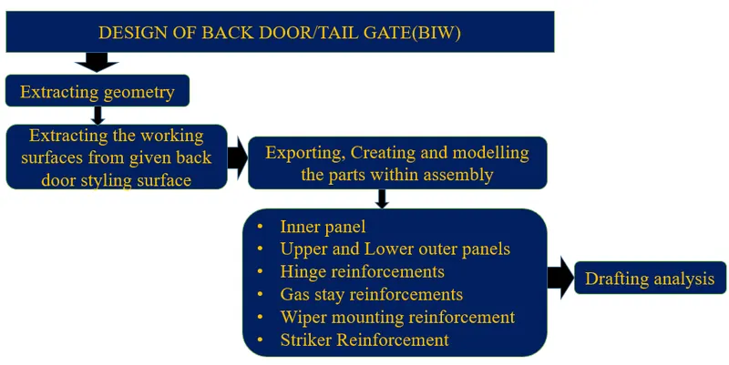
Manufacturing data:
- Outer panel thickness-0.75mm
- Inner panel thickness-0.75mm
- Reinforcements thickness-1.5mm
- Establish the relief at corners to reduce sress concentration.
Design Procedure:
- Open the assembly workbench.
- Add the upper and lower outer panel part files(Class A surface files) within assembly.
- Create the new part for developing the inner panel within the assembly and name it as inner panel.
- Open the inner panel part navigator and using the wave geometry linker, extract the working surfaces of upper and lower outer panel.These surfaces are used for creating the inner panel.
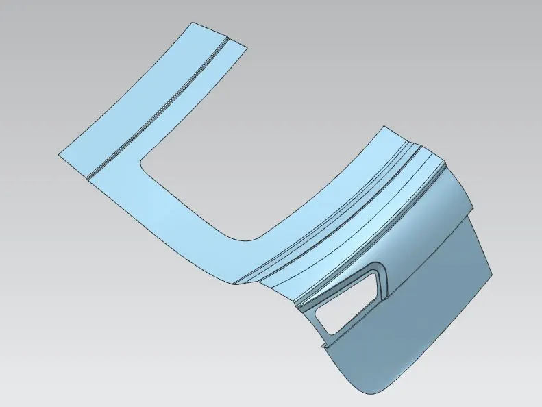
- Then after, create the tooling direction.It is the direction where the inner panel can be deep drawned during manufacturing in given tooling direction.
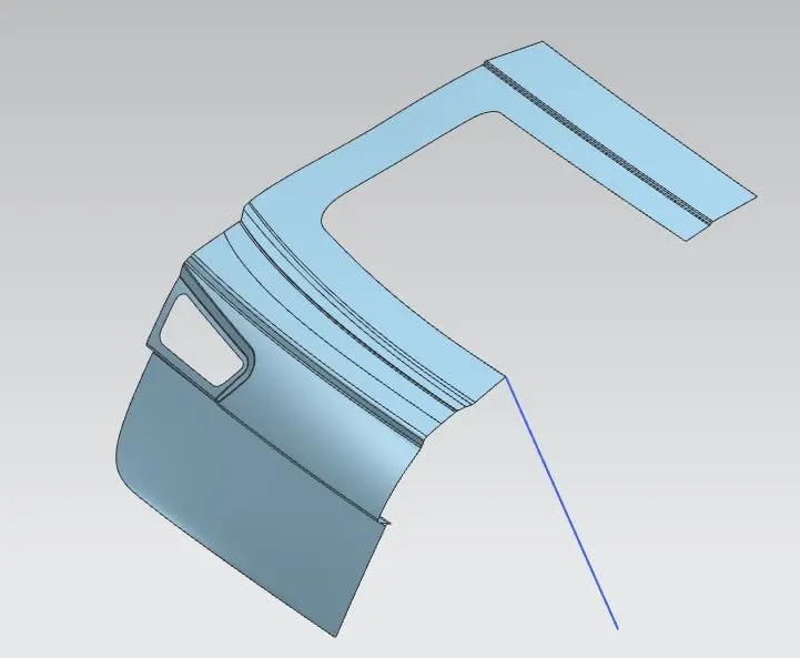
- After creating the tooling direction, firstly create the sealing flange.This flanged portion of back door presses a rubber strip of back body outer which acts as sealant between back door and luggage area in order to avoid any water obstacles to inside.
- So for that, I have offset the working surfaces to required distances and trim the unwanted portion using trim sheet and then generate the required studio surfaces guided by some bridge curves.
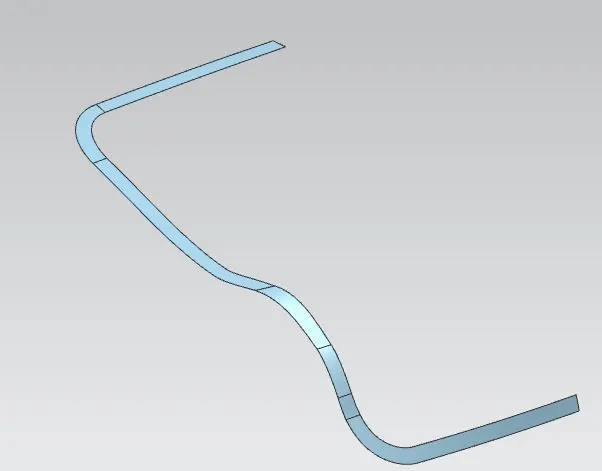
- Using law extension, develop the flange connecting to sealing flange.
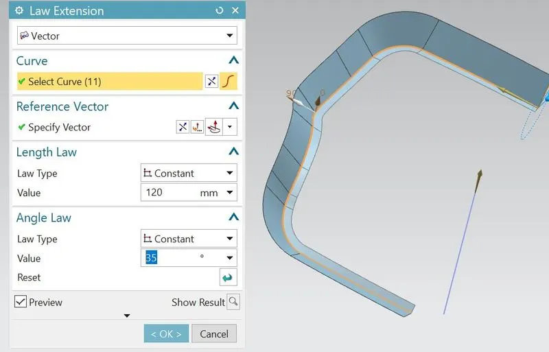
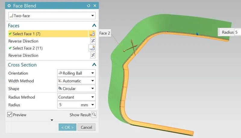
- Using face blend, create the blend between two flange faces.So then the connecting flange can be completed.
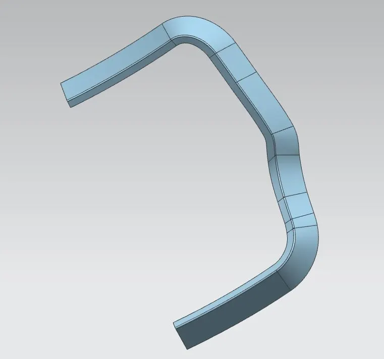
- Using the working surfaces and connected flange, develop the connecting blends by using trim and extend feature.
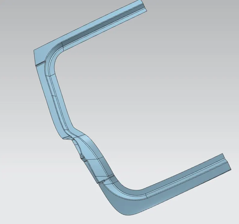
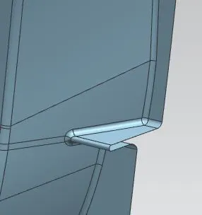
- Using law extension feature, Create the inner connecting flange connected with sealing flange.
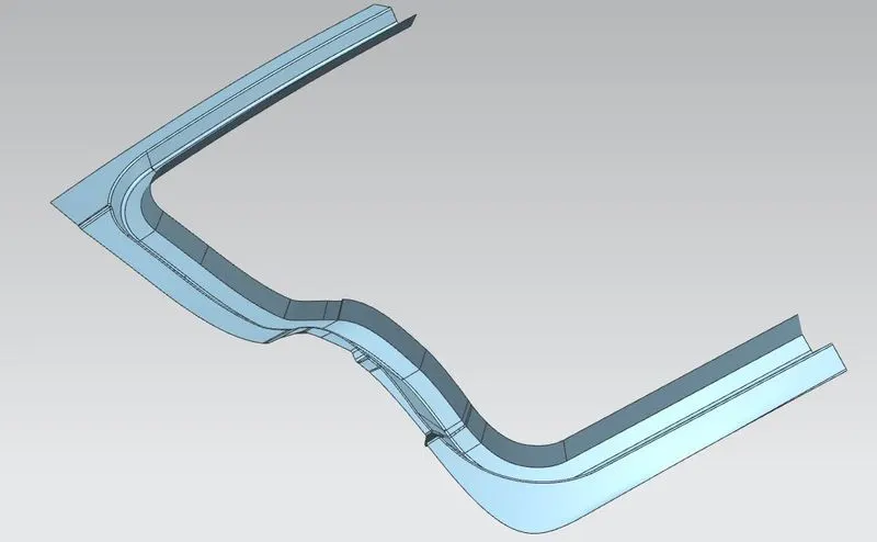
- Again using working surfaces & trim and extend feature, create the windshield area and bottom area of inner panel
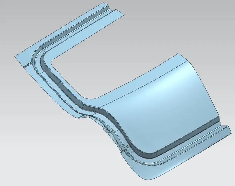
- Then after, I have created embosses on the inner panel for to increase the strength of panel and also remove some material to reduce the weight of part.The embosses are created with respect to the tooling direction in order to easily dissipated the forces towards outwards.
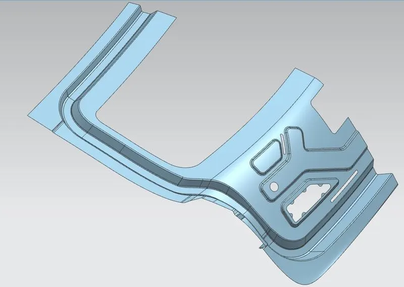
- Then after, a mastic flange can be created.This the flange of inner panel is attached to outer panel by the application of mastic sealant.Although the inner panel and outer panel is connected by hemming process at ends but this mastic flange helps to get connected at the centre portions.The gap between mastic flange and outer panel will be 5mm.So that only we can apply the mastic sealant between them.Each mastic sealant can cover 80mm area in diameter.
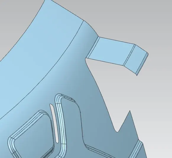
- Then after, I have created the flat emboss for mounting of hinge to the inner panel.The flat emboss must be maintain because it can increase the tightness between hinge and inner panel.Also maintain minimum 5mm space away from mounting holes for fasteners.Finally add the required blends to the hinge emboss.
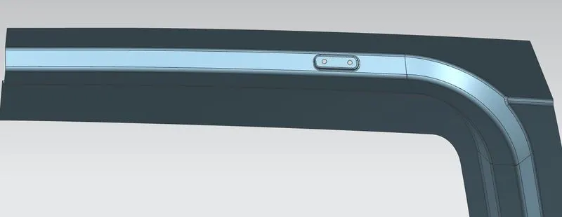
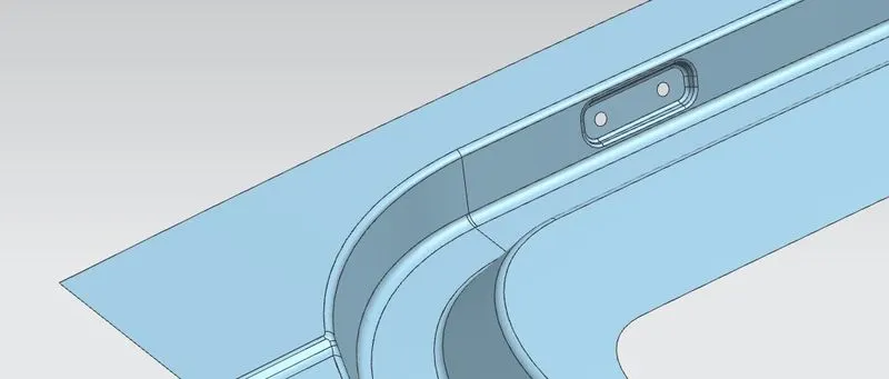
- Similarly, I have created the flat emboss for mounting of gas stay.The angle between hinge mounting and gas stay mounting must lie only in between 80 deg to 90 degrees.
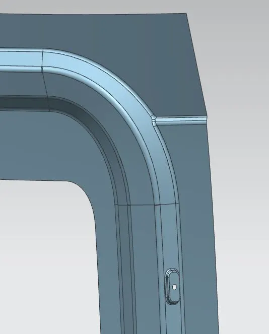
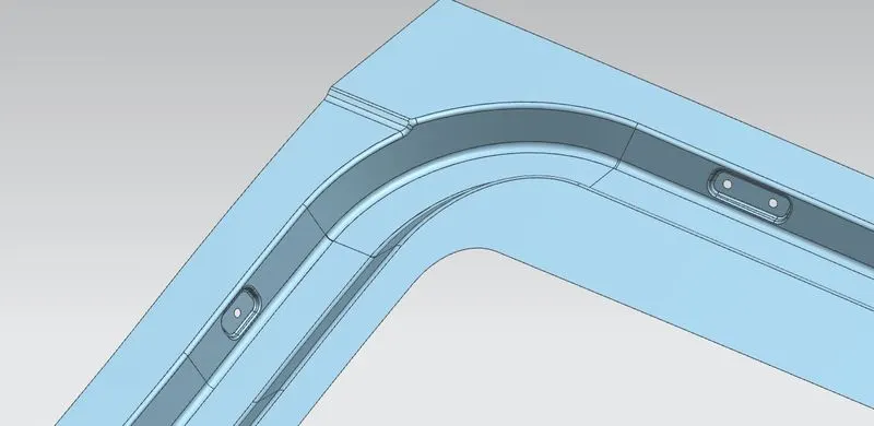
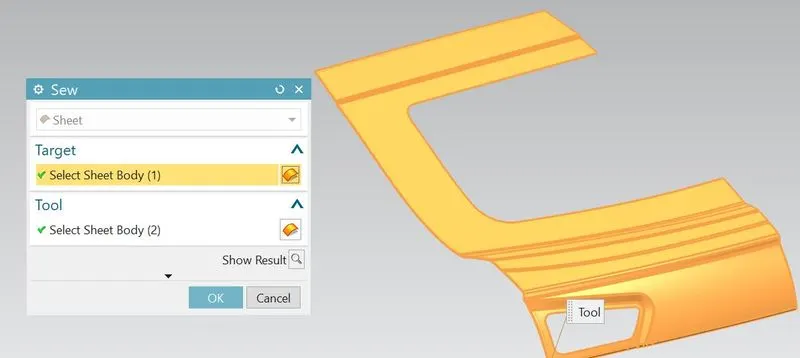
- So half of the inner panel is completed.Mirror it along XY plane to get complete panel and sew them together.
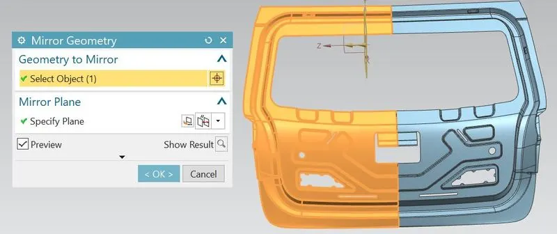
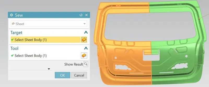
- For creating srtiker mounting region and for proper opening and closing of door,the striker should be positioned properly(perpendicular to trajectory of hinge axis).Here,I dont have any striker or hinges.So for that, I have drawn axis line betwen two hinge mountings.After that, a trajectory circle is drawn from centre of axis as it crosses the surface where the striker to be positioned.So then draw the line tagent to trajectory circle.The point where the tangent line and trajectory circle meets is the striker position.
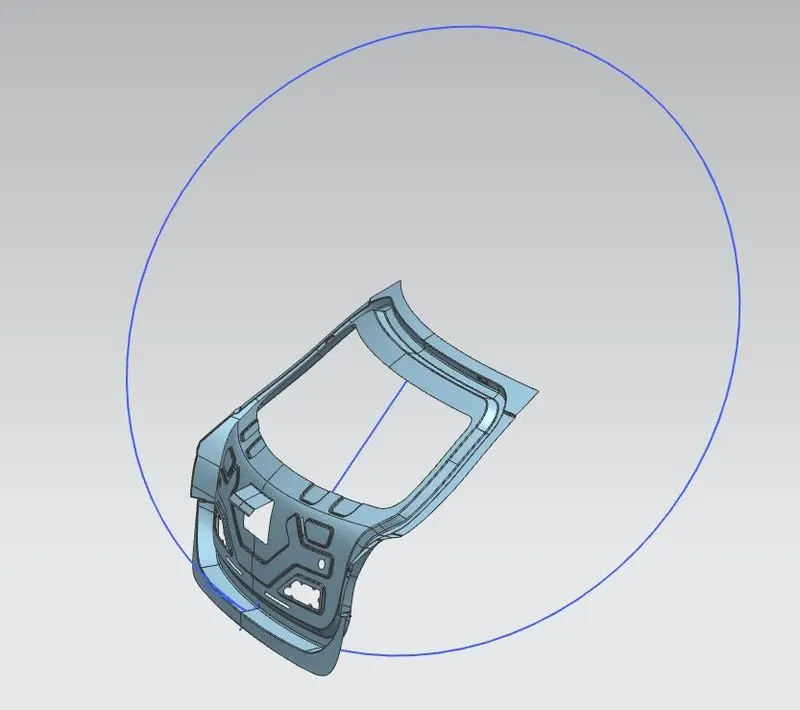
- So at that particular position, I have created the striker mounting area with flat emboss.
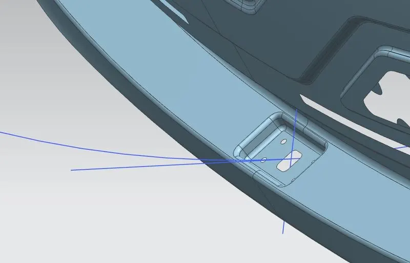
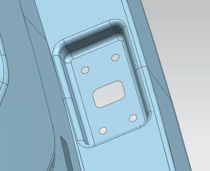
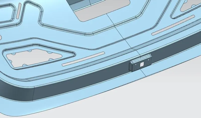
- After that, I have created the flat emboss for wiper mounting near the windshield glass area as shown.
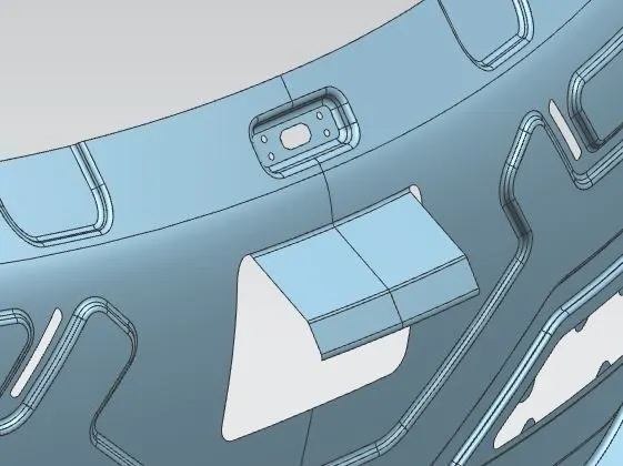
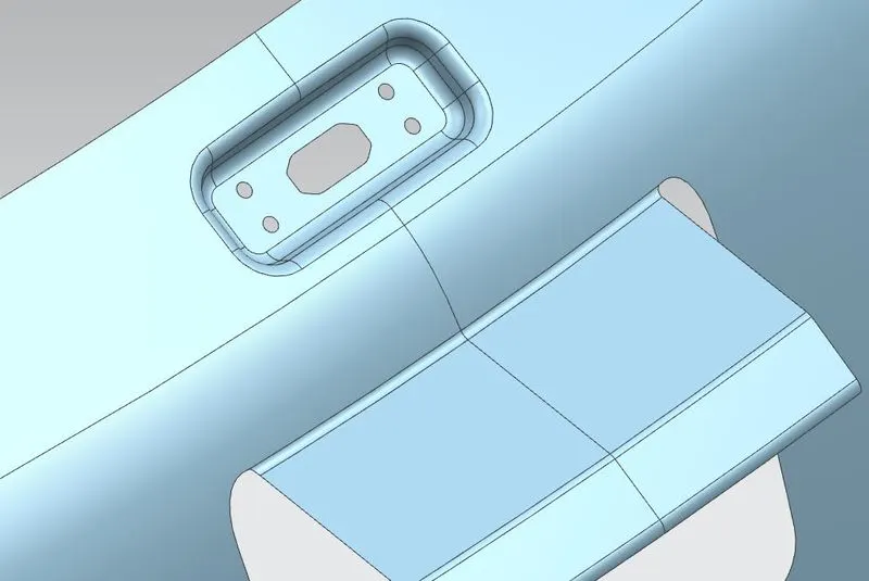
- Using the thicken feature, thicken the surface to 0.75mm and hide the sheet surface.So that thicken part can clearly visible.
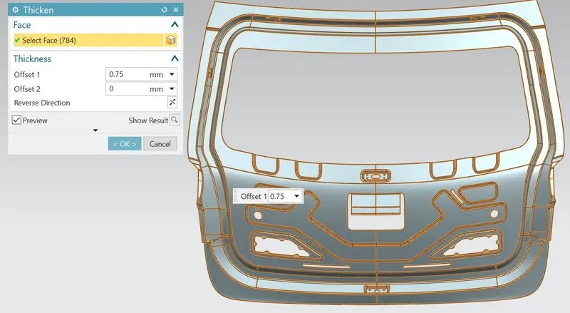
- So that inner panel should be completed.
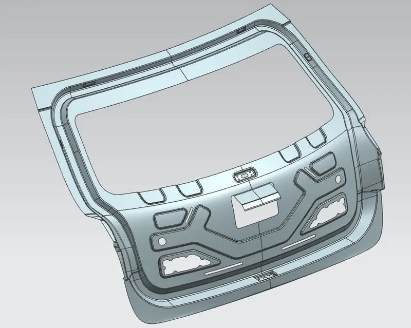
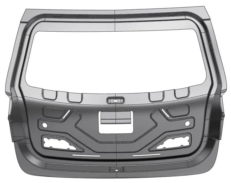
- For hinge reinforcement, create the new part in the assembly and name it as Hinge-Reinforcement-LH.
- Go to hinge reinforcemet part navigator, copy the required surfaces using the wave geometry linker.
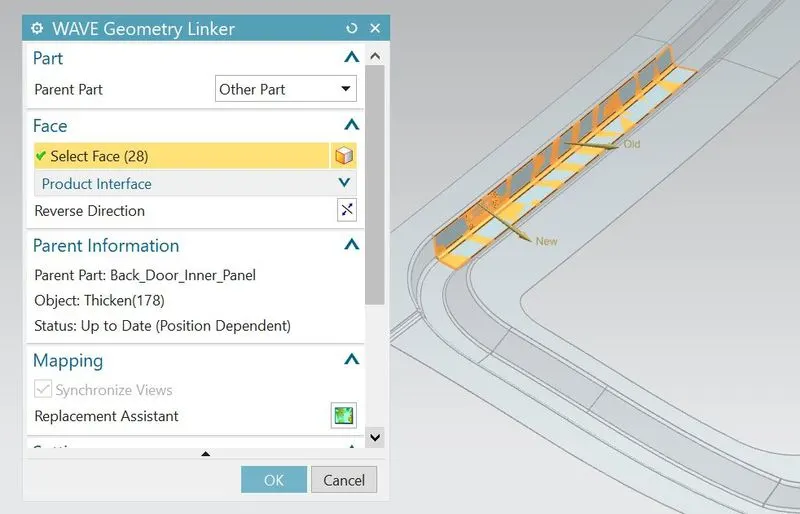
- Trim the excess sheet as per the requirement of reinforcement.
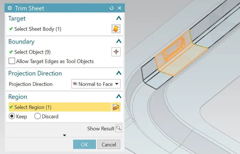
- Generate bridge curves on corners and trim the excess portion for to avoid sharp corners or edges.
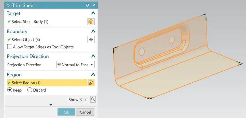
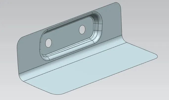
- Thicken the sheet to 1.5mm
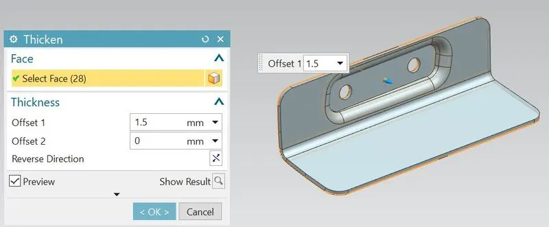
- So that hinge reinforcement on LH side should be completed.
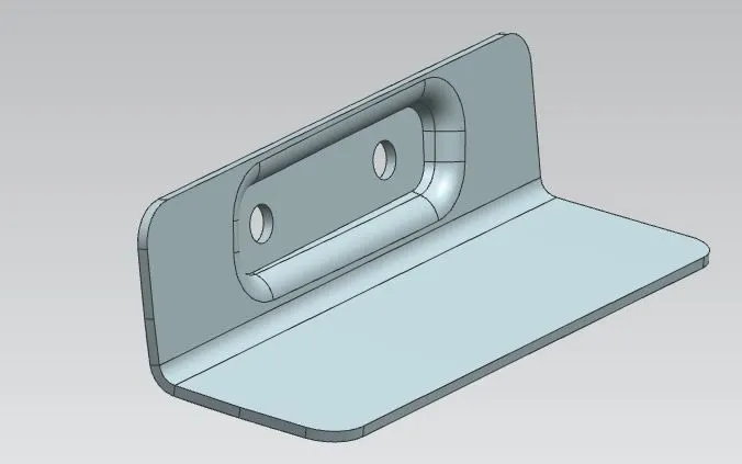
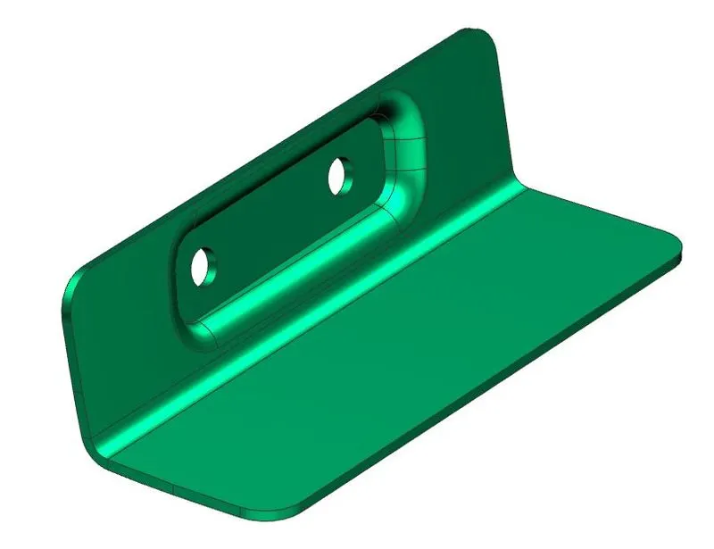
- Using mirror assembly feature, mirror the LH side reinforcement with respect to XY plane to get in on the Right hand(RH) side.
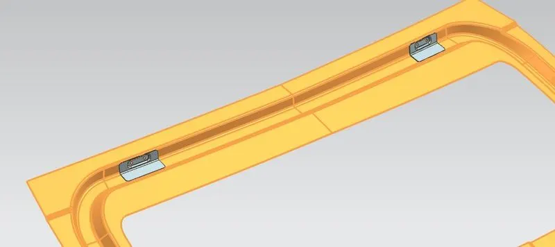
- For gas stay reinforcement, create the new part in the assembly and name it as Gas-stay-Reinforcement-LH.
- Go to gas stay reinforcemet part navigator, copy the required surfaces using the wave geometry linker.
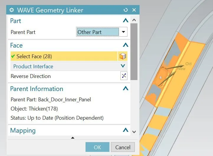
- Trim the excess sheet as per the requirement of reinforcement.
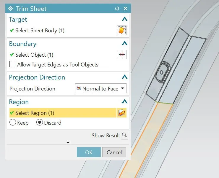
- Generate bridge curves on corners and trim the excess portion for to avoid sharp corners or edges.
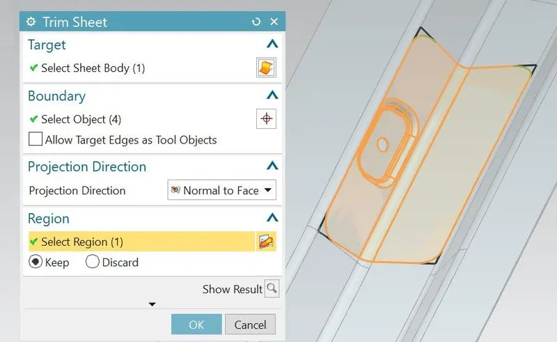
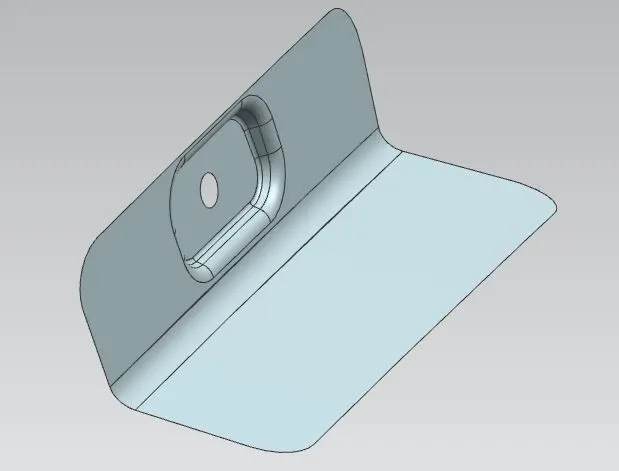
- Thicken the sheet to 1.5mm
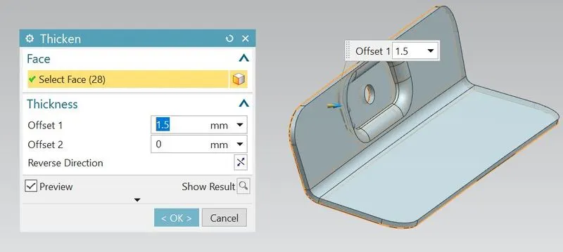
- So that Gas stay reinforcement on LH side should be completed.
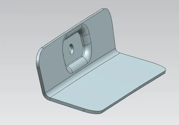
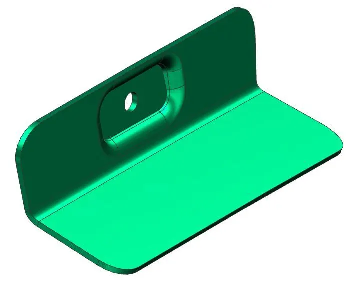
- Using mirror assembly feature, mirror the LH side reinforcement with respect to XY plane to get in on the Right hand(RH) side.
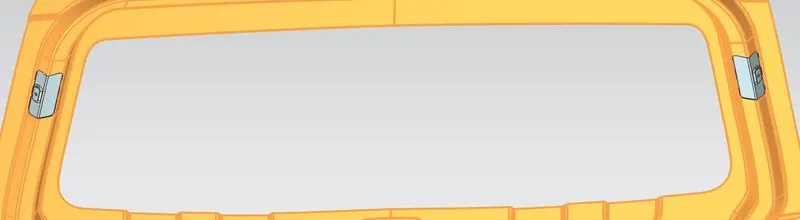
- For wiper mounting reinforcement, create the new part in the assembly and name it as Wiper-Reinforcement.
- Go to wiper reinforcemet part navigator, copy the required surfaces using the wave geometry linker.
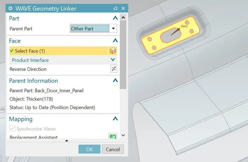
- Thicken the sheet to 1.5mm
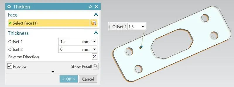
- So that wiper mountig reinforcement should be completed.
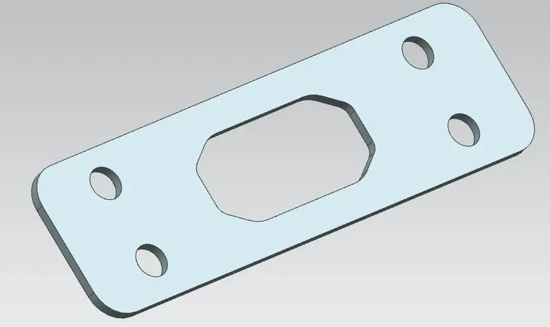
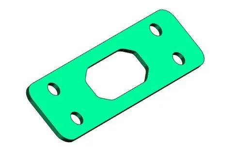
- For striker mounting reinforcement, create the new part in the assembly and name it as striker-Reinforcement.
- Go to striker reinforcemet part navigator, copy the required surfaces using the wave geometry linker.
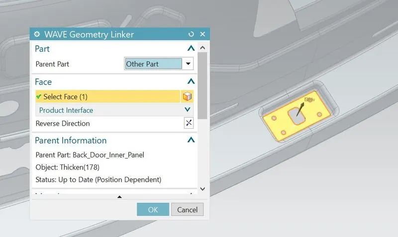
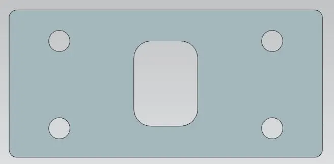
- Thicken the sheet to 1.5mm
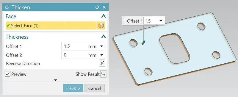
- So that striker mountig reinforcement should be completed.
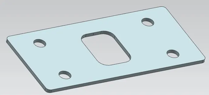
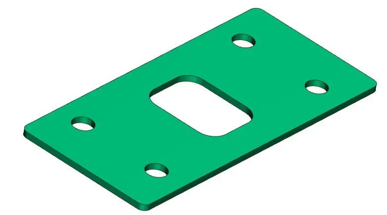
- Go to upper outer panel part navigator and extract the working surface from styling surface.
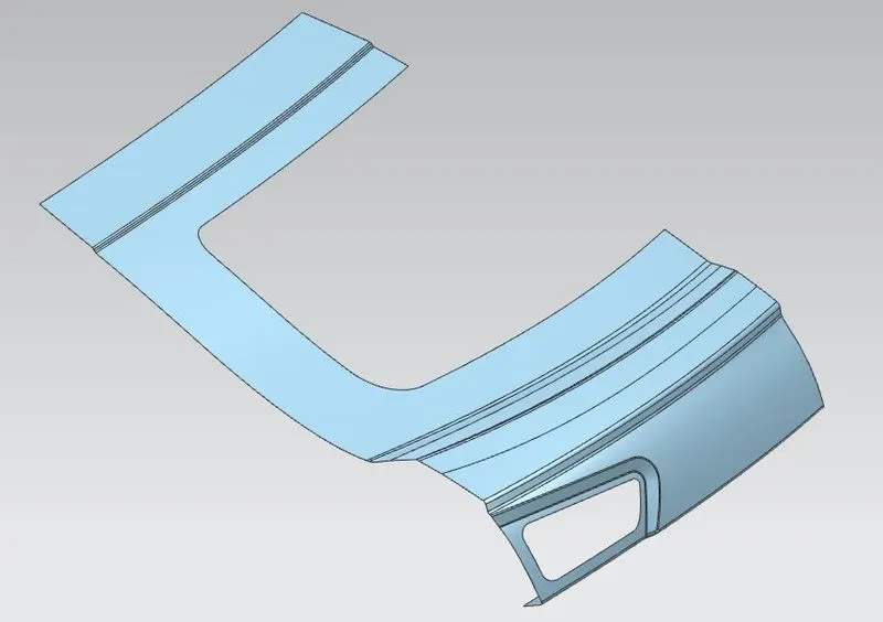
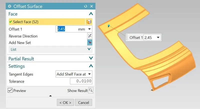
- Offset the working surface to 2.45 mm.
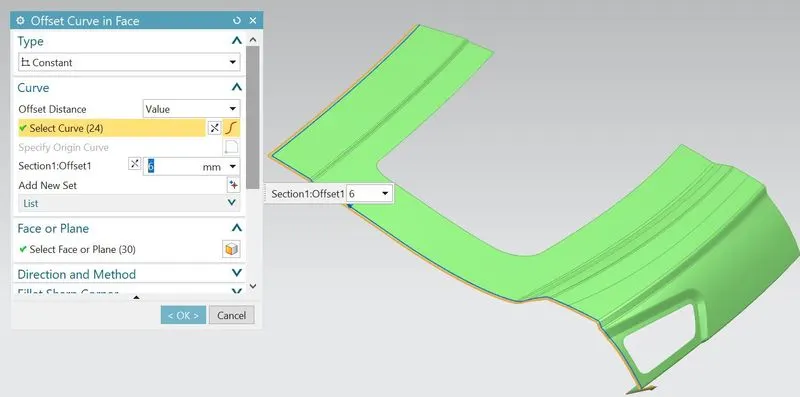
- On offset surface,offset the curve to 6mm for to create the hemming flange.
- Trim the offset surface excluding 6mm offset curve space.
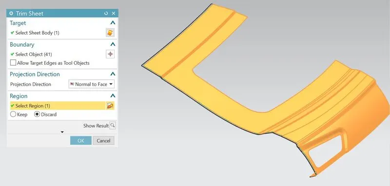
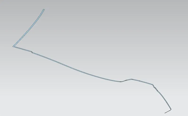
- So there are two flanges-one is upper flange and another one is 6mm lower flange.
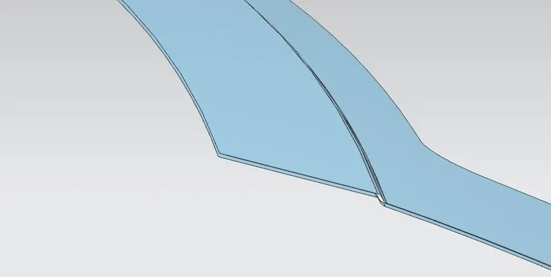
- Then after bridge the curves in between two flanges and developed the hemming by using swept, studio surface or through curves mesh features.
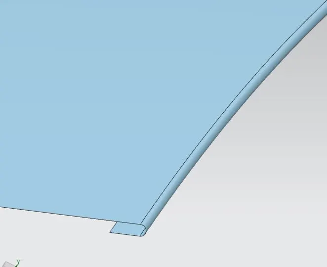
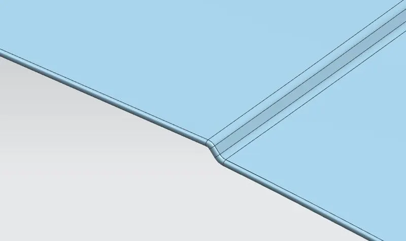
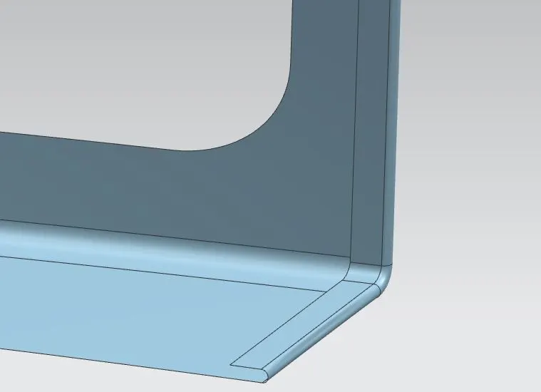
- Then after sew them all together.
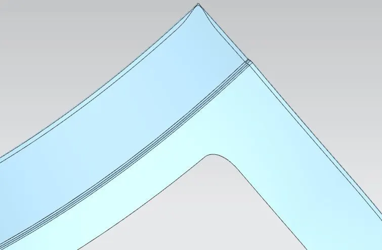
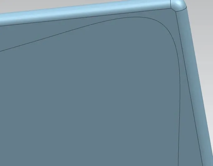
- For giving relief at the corners, draw the relief curve using spline feature and trim the excess portion.
- Mirror the panel along XY plane and sew them together.
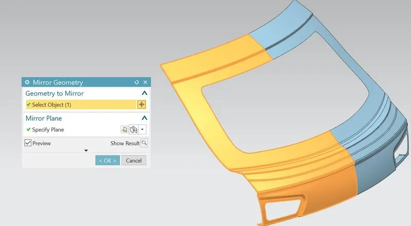
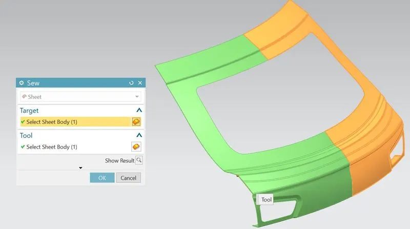
- Thicken the part inside to about 0.75mm.
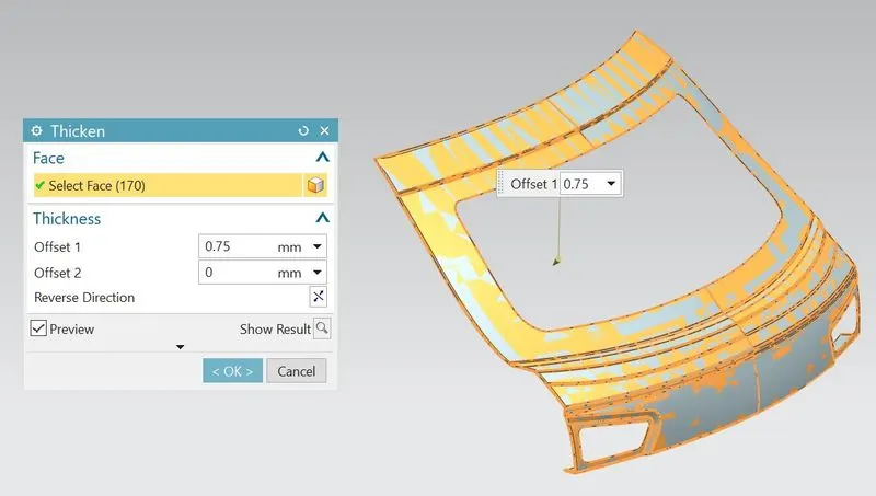
- So the Upper outer panel should be completed.
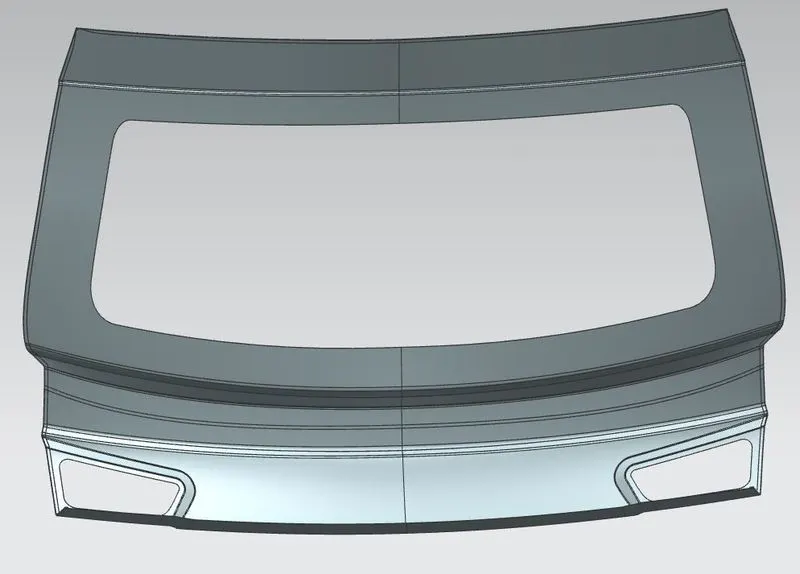
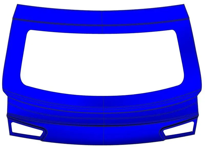
- Go to Lower outer panel part navigator and extract the working surface from styling surface.
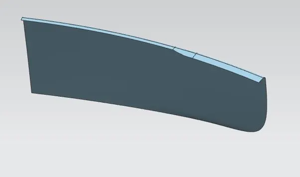
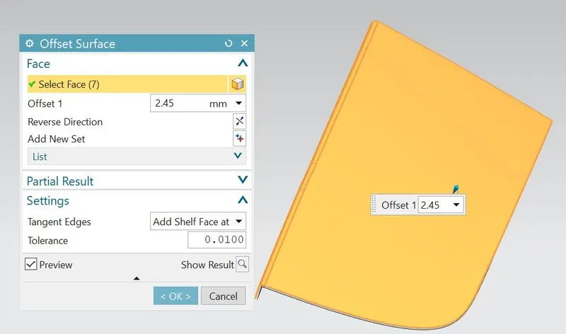
- Offset the working surface to 2.45 mm.
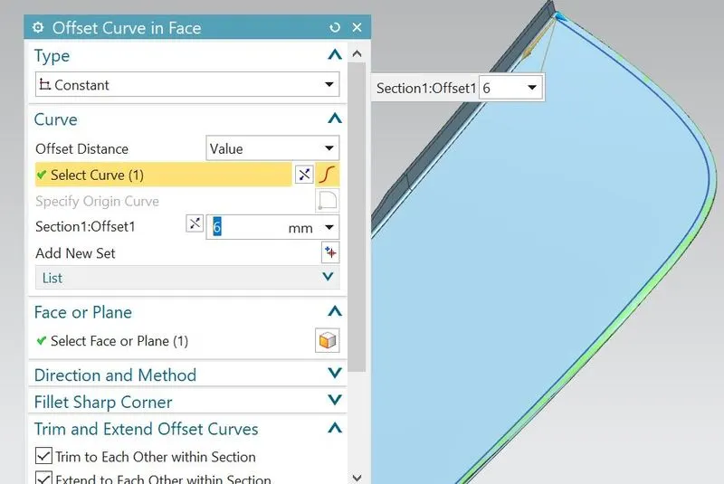
- On offset surface,offset the curve to 6mm for to create the hemming flange.
- Trim the offset surface excluding 6mm offset curve space.
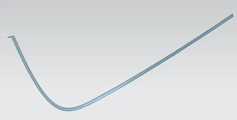
- So there are two flanges-one is upper flange and another one is 6mm lower flange.
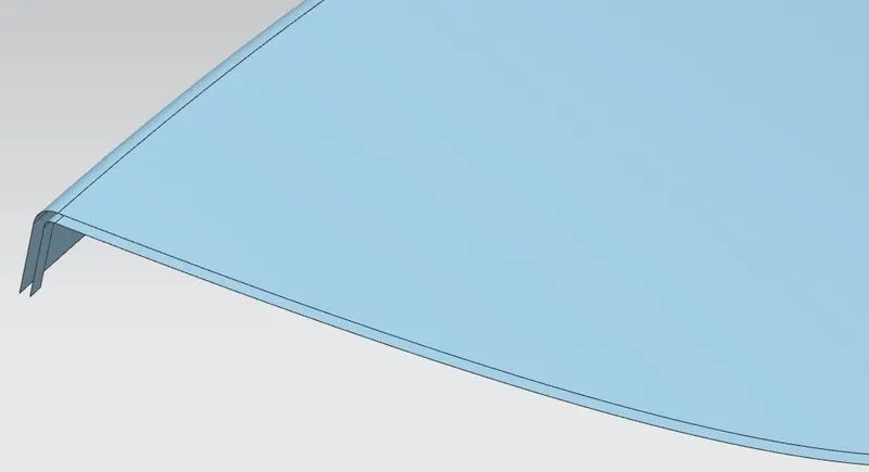
- Then after bridge the curves in between two flanges and developed the hemming by using swept, studio surface or through curves mesh features.
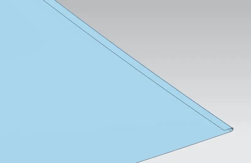
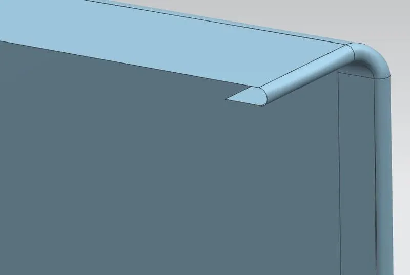
- Then after sew them all together.
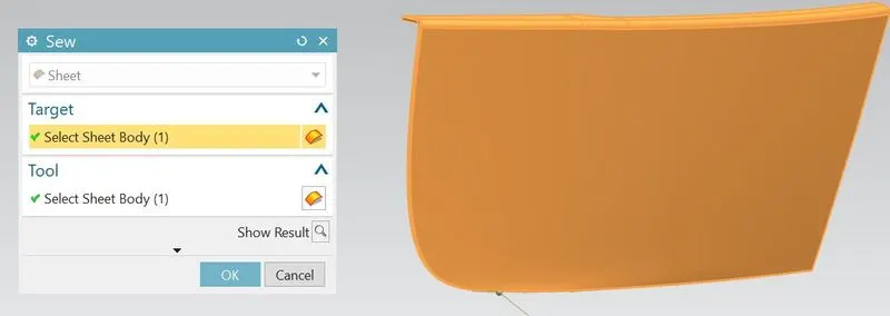
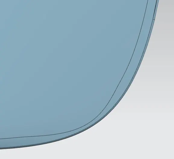
- For giving relief at the corners, draw the relief curve using spline feature and trim the excess portion.
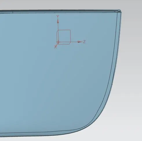
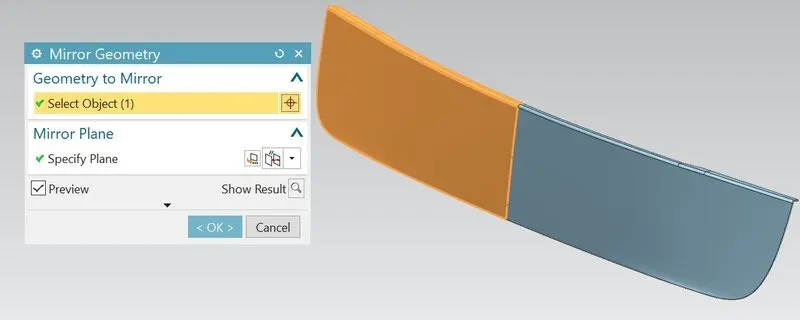
- Mirror the panel along XY plane and sew them together.

- Thicken the part inside to about 0.75mm.
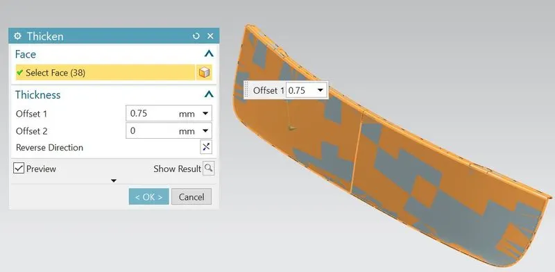
- So the Lower outer panel should be completed.
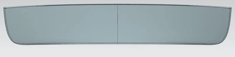
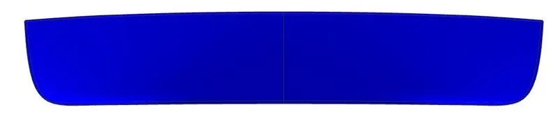
- Hence all the components of back door can be completed and assembled.After that, I have checked the various positions of back door i.e;satisfying as per manufacturing requirements or not.
Hemming section view
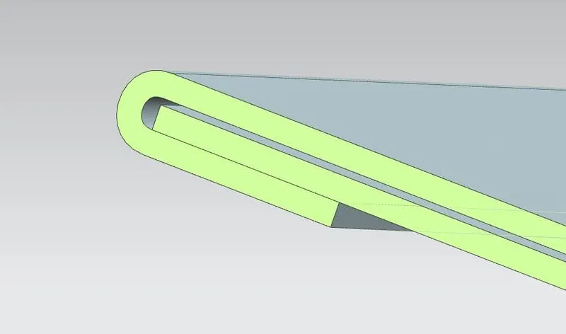
Position of upper and lower outer panel hemming flanges with respect to inner panel
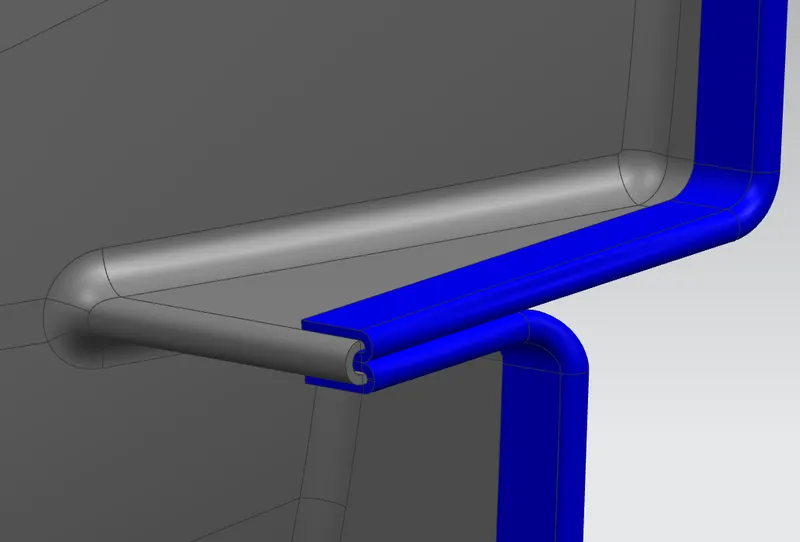
Corner reliefs on upper and lower outer panels
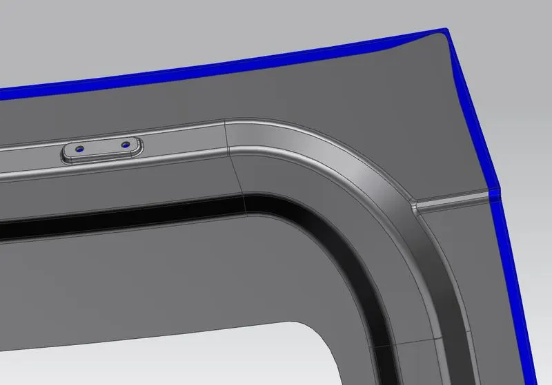
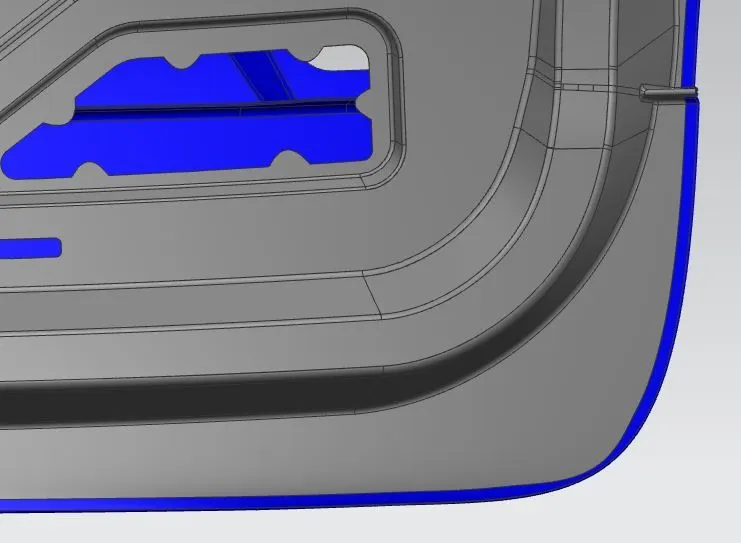
Mastic sealant area(Maintained 5mm gap between inner and outer panel)
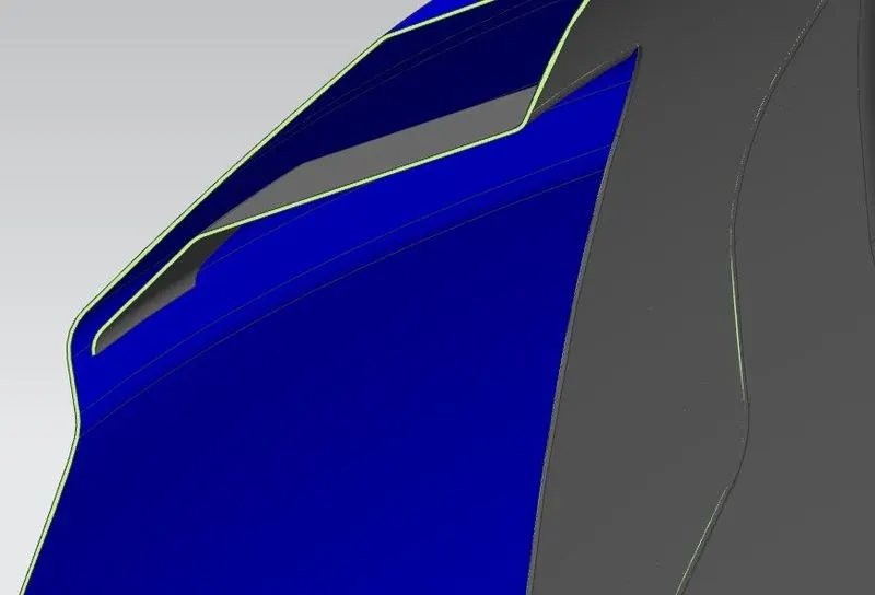
Reinforcements assembly positions on inner panel
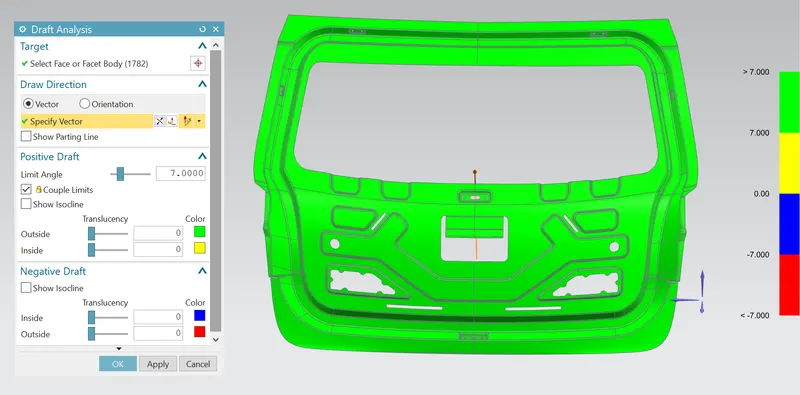
Draft Analysis:
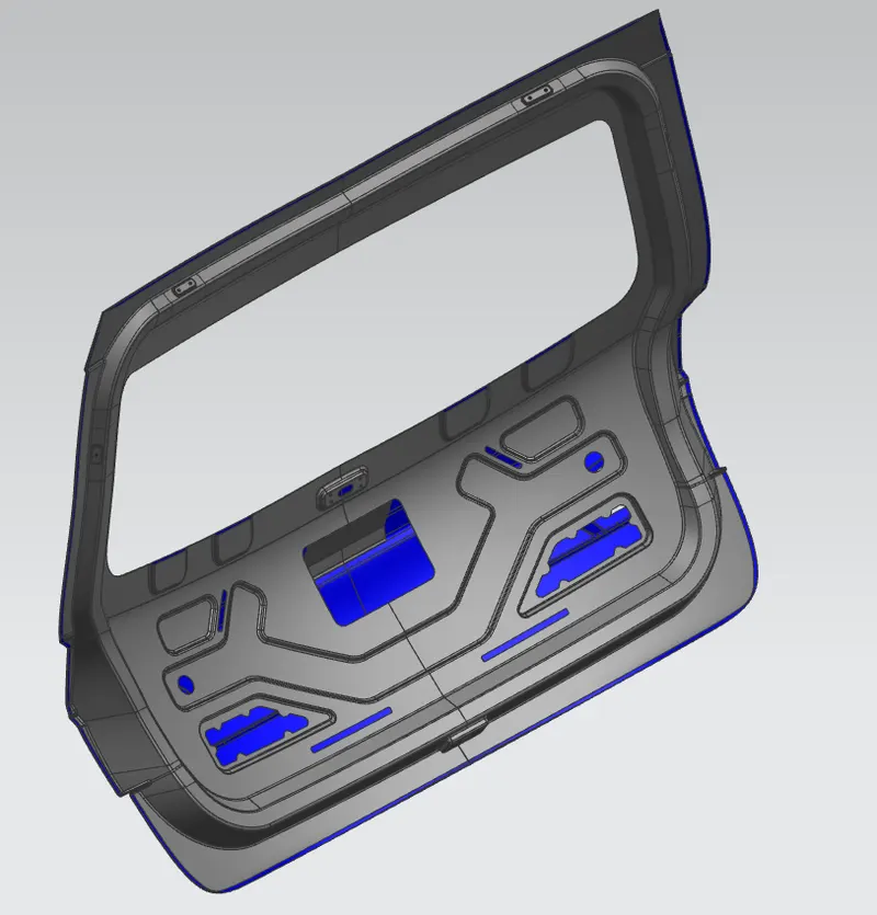
Draft analysis is a tool to check the correct application of draft to the faces of their part and verifies the draft angles or examine angle changes within a face.It commonly detect whether the designed component within the positive draft or negative draft.Positive draft means the angle of face with respect to the direction of pull is more than reference angle.Negative draft means the angle of face with respect to the direction of pull is less than the reference angle.
In the NX software, the draft analysis tool represents draft result with colour zones.The minimum draft angle of steel is 7° and it is considered as positive draft in the analysis which represents as green colour.If the draft angle is less than 7°,it identifies the component having negative draft and can represent in yellow, Blue and red colours.
Assembly views of Back Door:
Image1
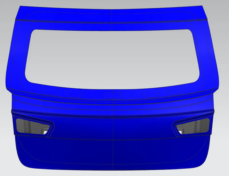
Image2
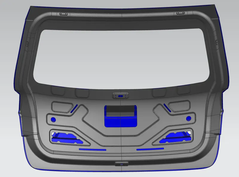
Image3
Conclusion:
Design and assembly of back door(BIW) along with its reinforcements can be successfully designed as per the manufacturing requirements and functional requirements by using NX-CAD software and also got a advanced knowledge on surface tools or commands.
THANK YOU