Advanced Sheet Metal Design Using NX Cad Challenge_7_ Metal bracket-II
DESIGN OF SHEET METAL BRACKET-II BY USING NX-CAD SOFTWARE
Aim:The main aim of this project is to design the sheet metal of Bracket-II by using sheet metal workbench within the NX-CAD software.
Introduction:Metals formed into thin pieces from the various forming process like bending, cutting, punching, embossing etc is known as Metal sheets.They are made up from the materials like aluminium, copper, brass, titanium, galvanized steel etc.Each use for sheet metal requires a specific thickness or guage.A higher guage number indicates a thinner piece of material.These are used even from small light applications to large applications like in car bodies,airplane wings,medical tables,casing plates etc; because of their high durable strength,low in weight,cost effectiveness and mostly it is free from corrosion.
In this project,a sheet metal of bracket is designed by using the NX-CAD software.Actually sheet metal brackets are the mounting components used for mounting purpose on the various formed products because of their high strength. Coming to software, NX is the computer aided software formerely known as unigraphics.Firstly it was introduced solid modeling, surface modeling features and gradually sheet metal metal application is also came into existence.It having several widely used sheet metal features like flanges,normal cutout,corners,unbending,rebending,gusset etc and also it converts non sheet metal parts into valid sheet metals.By using this features,bracket can be designed accurately and also generate the drafting of bracket by using drafting feature.
Design Methodlogy:
Design of sheet metal bracket involves a application of various normal,advanced features and several sketches are to be created.The detailed workflow on how to desgin the bracket is described below.
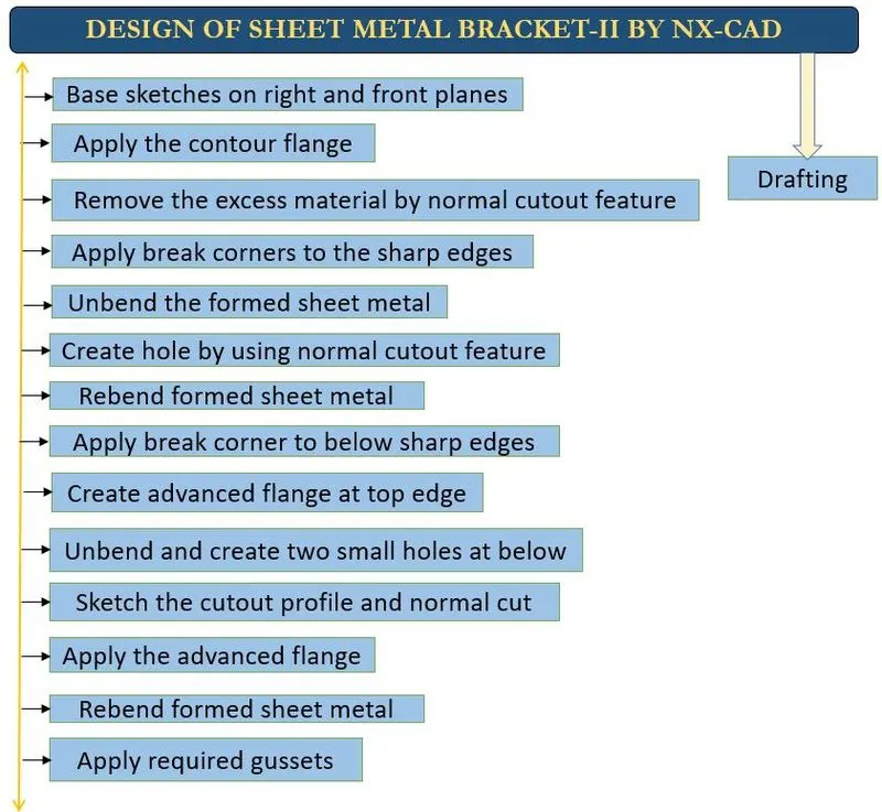
Features used for designing sheet metal bracket:
Sketch:Sketch creates the 2D drawing for which the model is to be designed.It consists of several sketch tools like line arc,rectangle, spline etc.
Contour flange:It is used for extruding the sketch along the defined vector direction for non linear profiles.It consists of base as well as secondary cotour flanges.
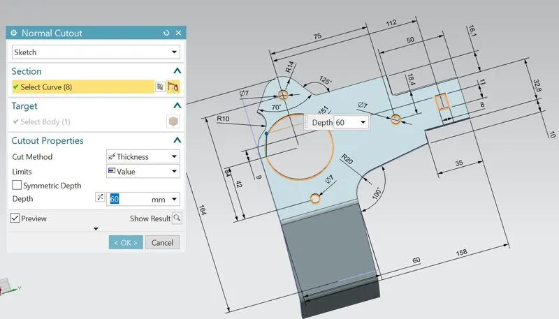
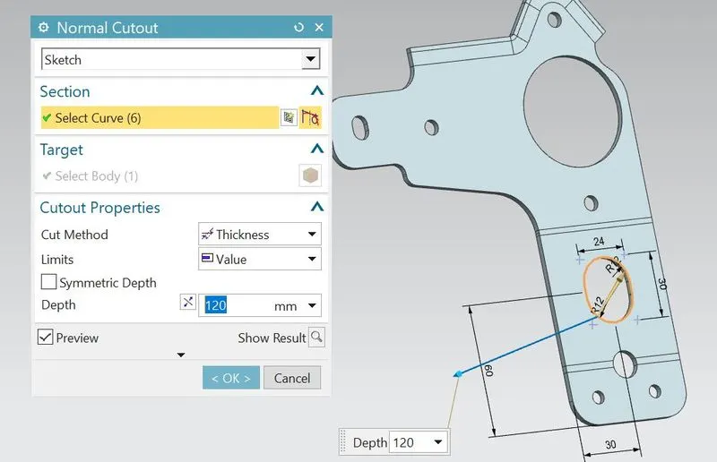
Normal Cutout:It is used for removing the material by projecting sketch onto the model and then cutting perpendicular to the faces intersected by the projection.
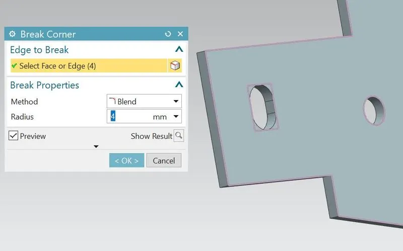
Break Corner:This feature is used for creating smooth faces at the edges in order to avoid Sharp edges.
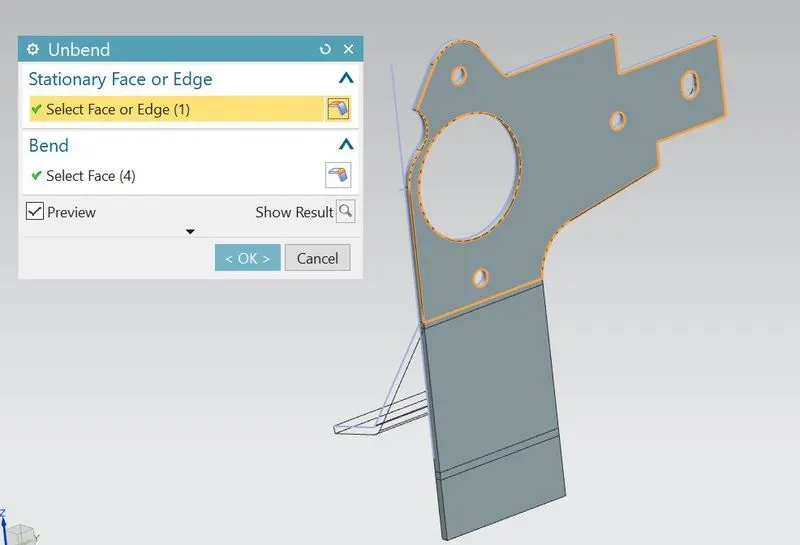
Unbend:Unbend feature converts the formed bended sheet metal into flat sheet metal by using one of the stationary face as flat face.
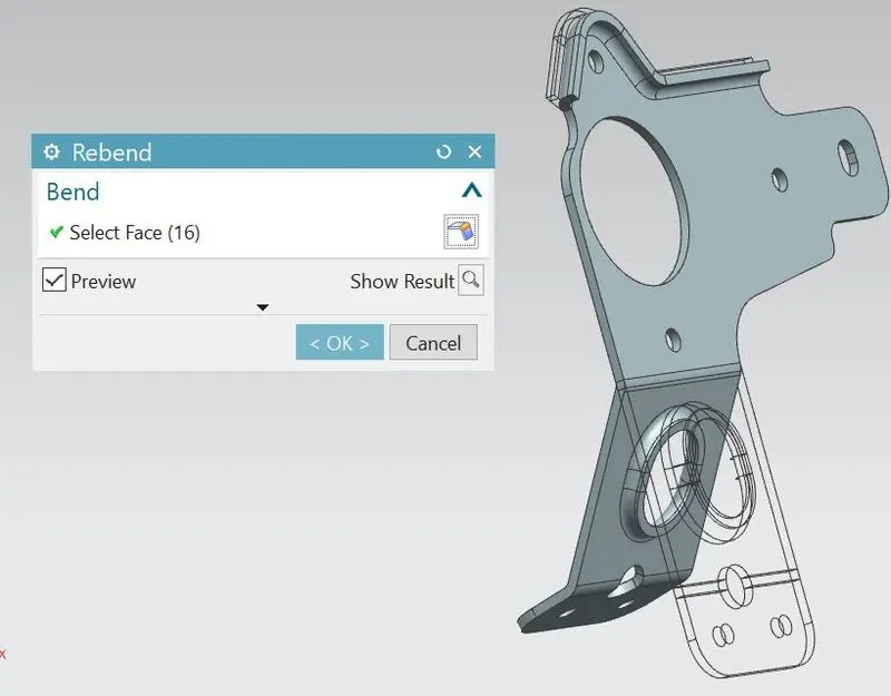
Rebend:Rebend is used to revert the flat sheet metal into bended form.
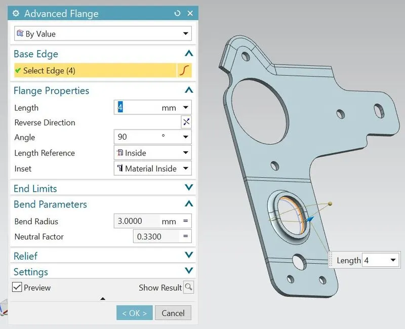
Advanced flange:This is the advanced feature in sheet metal features and it is as similar to normal flange.Normal flange will extend the material along the straight edge where as advanced flange extend the material along the tangential edges.
Gusset: Gusset is the stiffening feature which is mainly used for providing additional strength to the sheet metal.Gusset can be applied on the bend faces along specified plane direction.
Description:
- First open the NX application from the start menu,select model workbench and change unit system to millimeters.
- Select sheet metal ribbon from application tab.
- Create the new sketch on YZ plane(Right plane) and draw the profile as per dimensions as shown.
- Exit from sketch.
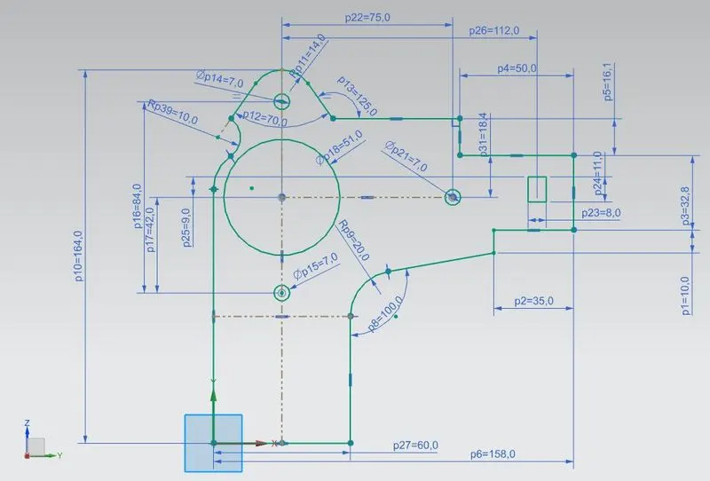
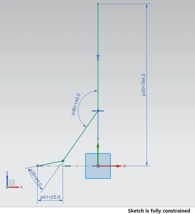
- Create new sketch on XZ plane(Front plane) and draw the profile per dimensions shown below.
- Exit from sketch.
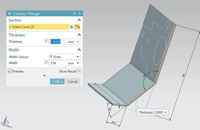
- Create contour flange by selecting sketch2 as section curve
- Change thickness to 3mm and width as 158mm.
- Remove the excess material using sketch1 profile with normal cutout feature.
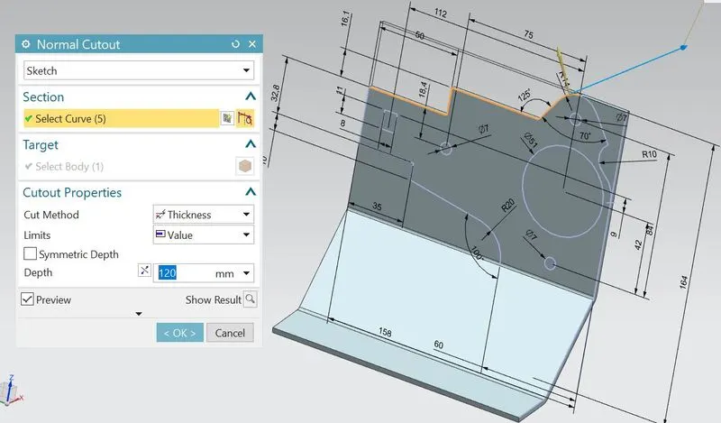
- Remove the additional excess material using sketch1 profile with normal cutout feature.
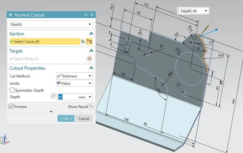
- Apply the break corner on the edge between two faces with radius 4.5mm.
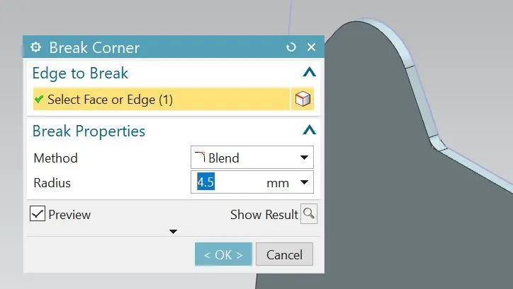
- Remove the additional excess material using sketch1 profile with normal cutout feature.
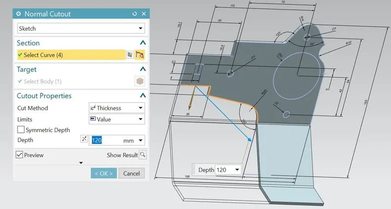
- Similarly remove the additional excess material using sketch1 profile with normal cutout feature.
- Apply the break corner on 4 corner edges of rectangle slot with radius 4mm.
- Unbend the formed sheet metal by selecting orange colour face as stationary face.
- Create new sketch on the surface of YZ plane.
- Draw the circle as per dimensions below.
- Exit from sketch.
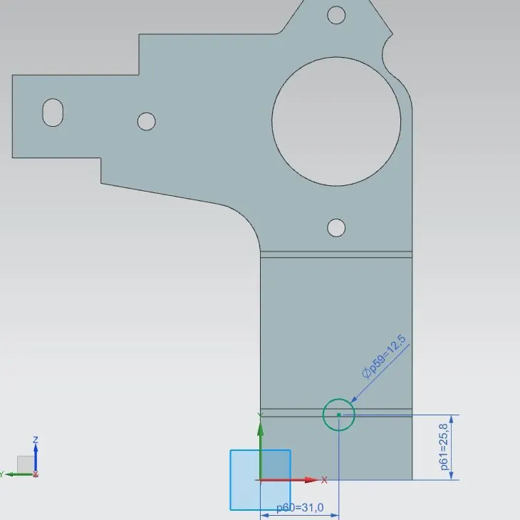
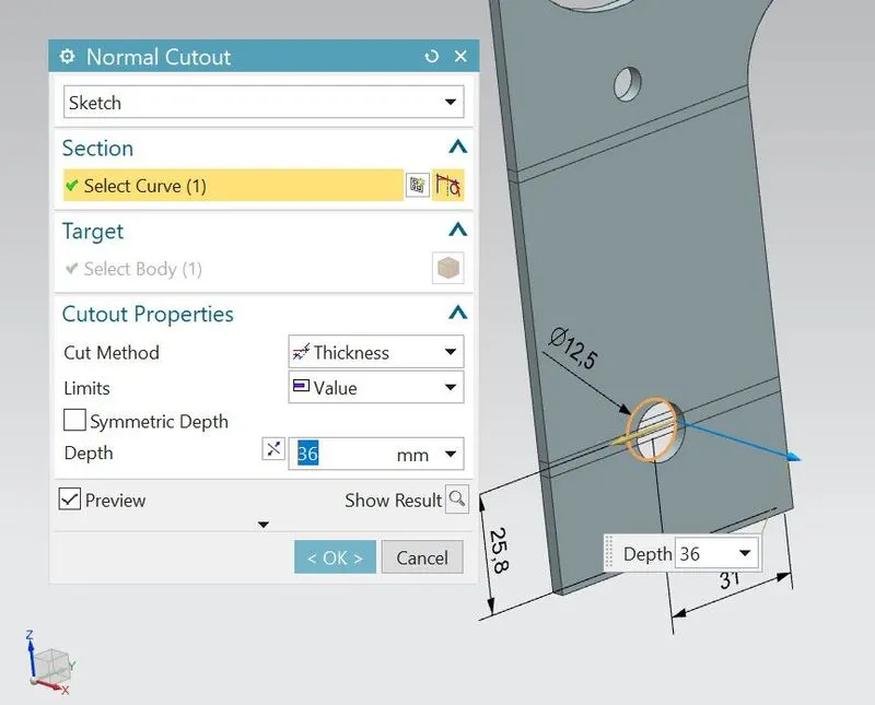
- Remove the circle portion material by using normal cutout feature.
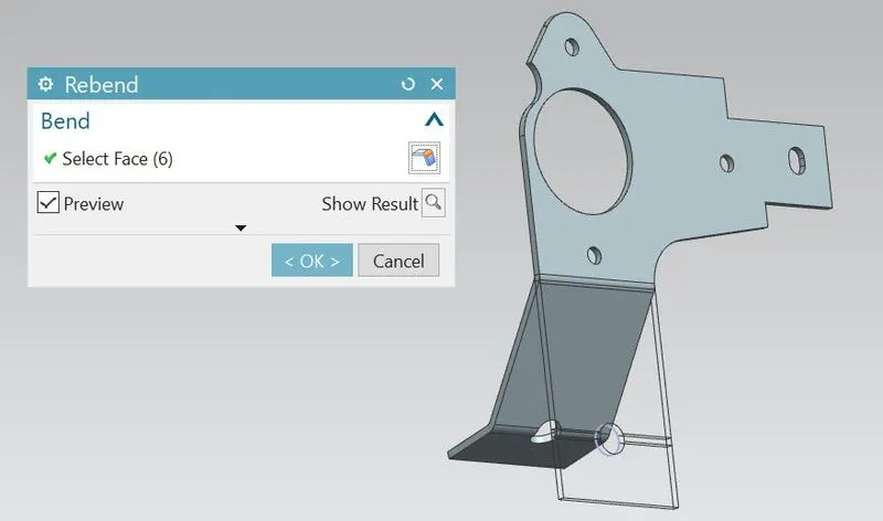
- Rebend the formed flat sheet metal.
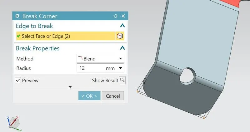
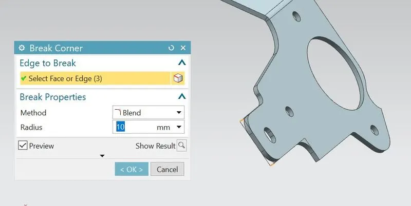
- Apply the break corner at bottom two corner edges with radius 12mm.
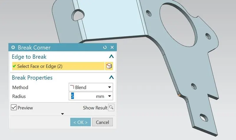
- Apply the break corner at orange colour edge with radius 5mm.
- Apply the break corner at two side corner edges with radius 10mm.
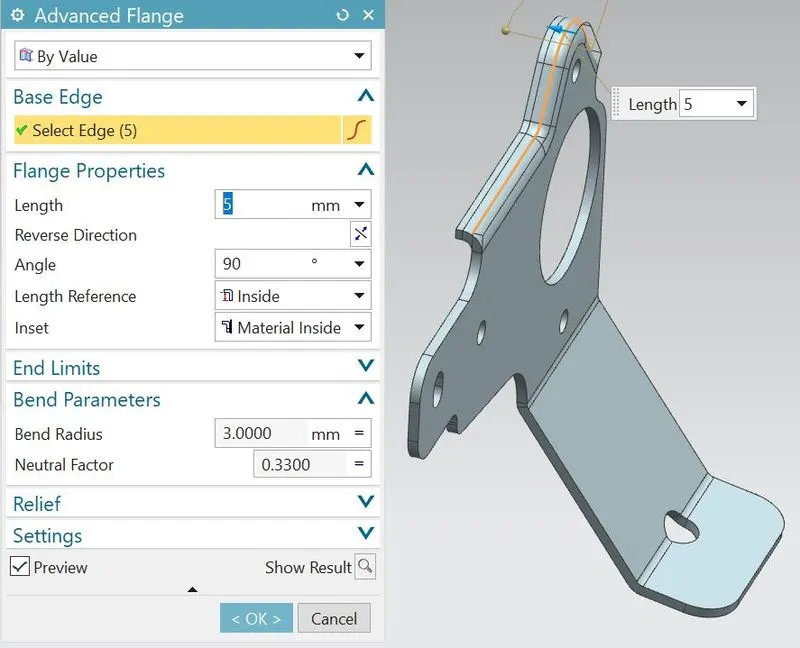
- By using advanced flange, generate flange by selecting the orange colour edge as shown.
- Change flange properties of length 5mm and angle 90 degrees.
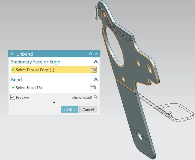
- Unbend the formed bended sheet metal by selecting orange face as stationary face.
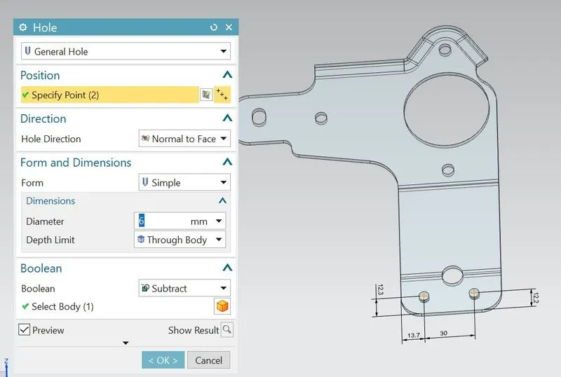
- Open the hole feature and by using the sketch creation,create the two points with required dimensions as shown.
- Exit from sketch and then holes are generated at positioned points.
- Change the hole diameter to 6mm.
- Create new sketch on the surface of YZ plane.
- Draw the profile as per dimensions shown below.
- Exit from sketch.
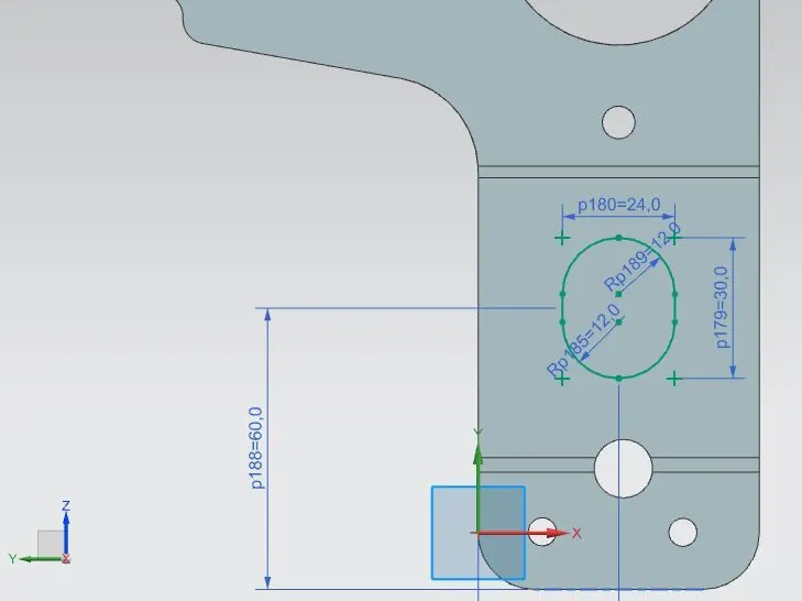
- Remove the sketched portion material by using normal cutout feature.
- Using advanced flange,extrude the material from previous cutout edge.
- Change length to 4mm and angle 90 degrees.
- Rebend the formed flat sheet metal.
- Apply the gusset on the bend face with distance -15mm from the selected face.
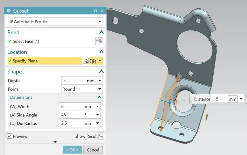
- Apply the gusset on the bend face with distance -15mm from the selected face.
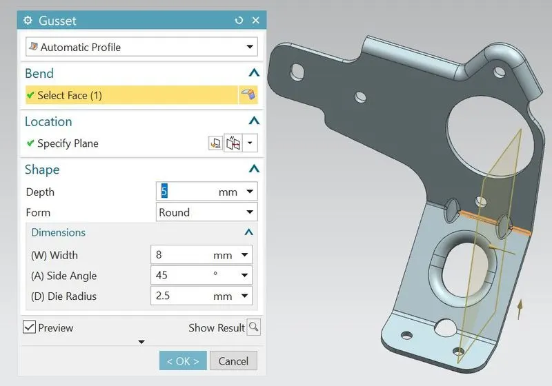
- Apply the gusset on the bend face with distance -15mm from the selected face.
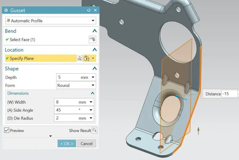
- Apply the gusset on the bend face with distance -15mm from the selected face.
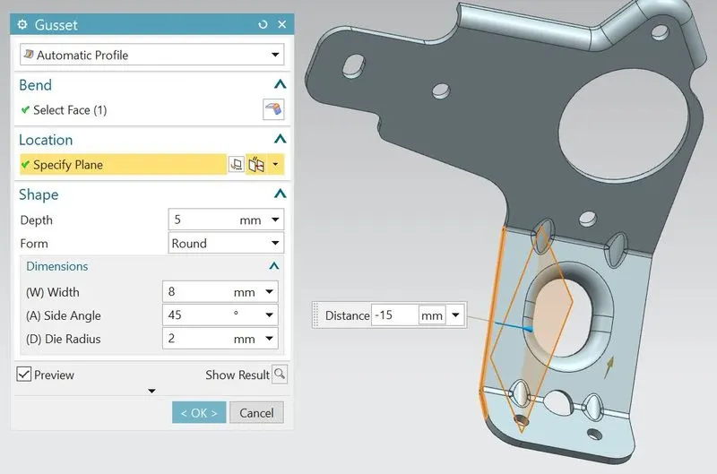
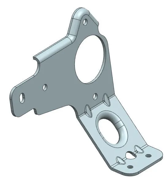
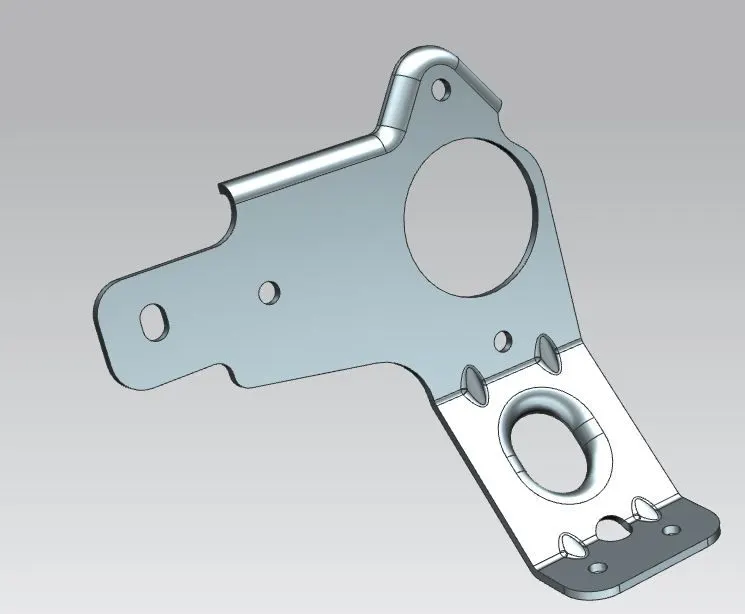
- Finally the design of bracket is completed and can be look like this.
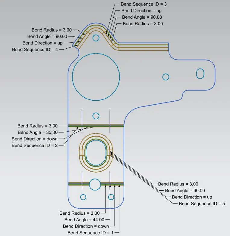
- Create the flat pattern view of bracket for determing total blank properties and parameters and thereby extremely used in drafting as additional view.
- After that select the drafting ribbon from the application tab.
- Automatically it opens the sheet dialogue box and select sheet size as per requirement.
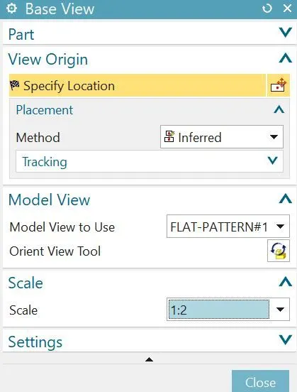
- Select base view tab feature and select flat pattern as model view.
- Select the suitable scaling ratio based on the model view.
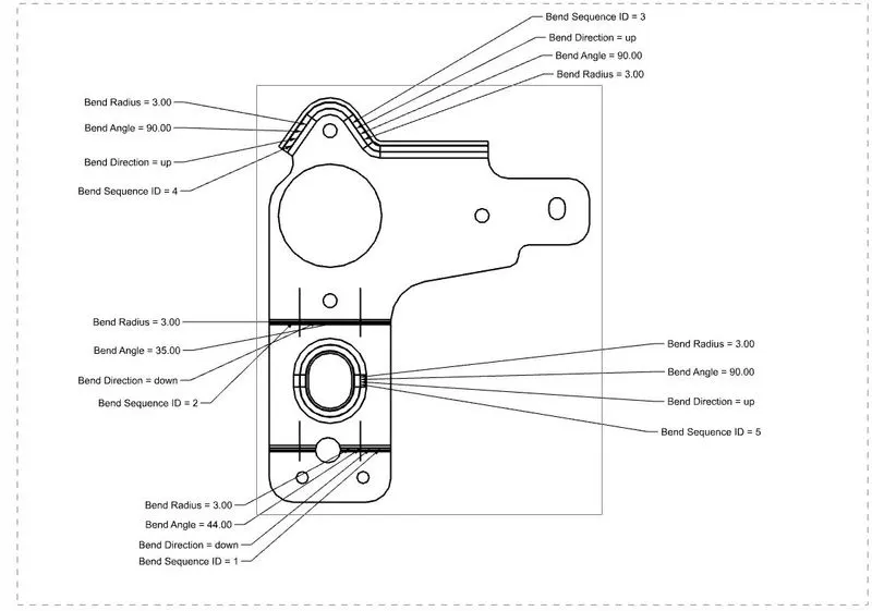
- Once the drafting is completed,click on save button to save the entire work.
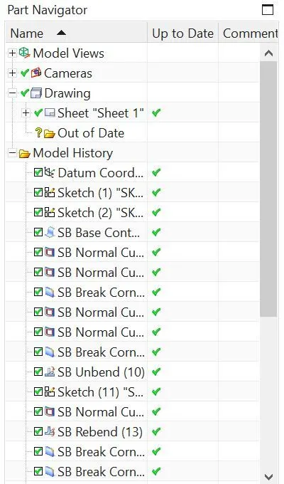
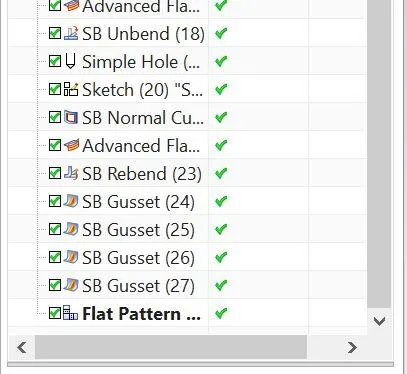
Feature tree of Bracket part navigator:
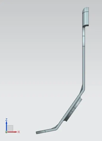
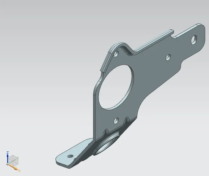
Different views of sheet metal bracket:
Front view
Top view
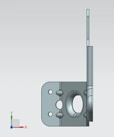
Left view
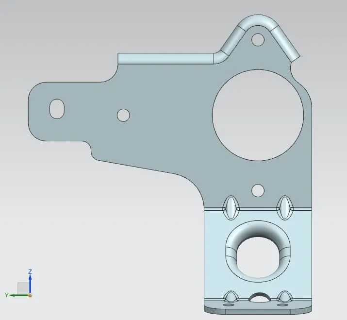
Isometric view
Final model image:
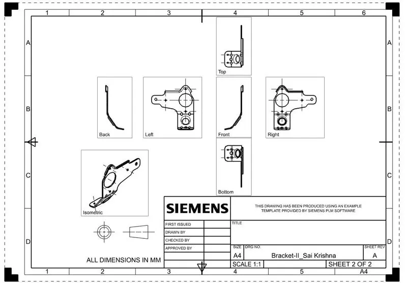
Drawing sheet images:
1.Image with flat pattern view-
2.Image with proper standard views-
Conclusion:
Design of sheet metal bracket-II can be completed by using several normal features along with the advanced feature like advanced flange from the sheet metal workbench within the NX-CAD software.
THANK YOU