Radar Mast & Final Assembly of Yacht
MODELLING AND ASSEMBLY OF AN SUNSEEKER PREDATOR YACHT
Objective:
The main aim of this project is to model the parts and assembly of an sunseeker predator yacht, also to gain a knowledge on how to convert this CAD model into rendered model for the photo-realistic purpose.
Introduction:
In this project the sunseeker predator yacht can be designed by using the solidworks.To design this model it requires a lot of surface modelling and solid modelling features and it can be done by using Solidworks .Initially start with designing the individual parts using the part model template and after that enaging those parts into single assembly file by using the assembly template of applying with the several mating relations like concentric,coincident etc.
During this designing, the blueprints of yacht can be taken as reference purpose because it really helps us of matching the exact yacht profile.Whle giving the dimensions for designing its defines only the size and shape parameters,not exactly the profile parameters.For example,designing of yacht requires a spline feature.so its not only require the dimensions but also needs good curvature and it is resolved by using the blueprint set up.
Solidworks also provides the rendered models,because after the completion of CAD model the looking and appearnce is not as realistic.So solidworks helps us of generating the photo-realistic models by using the photoview 360 and solidworks visualise.
Design Methodlogy/Approach:
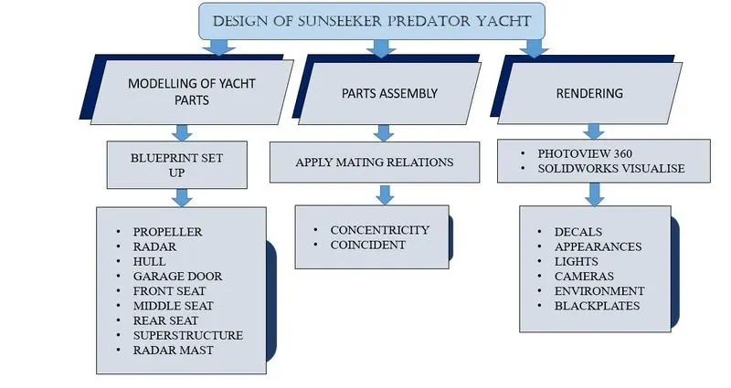
MODELLING OF YACHT PARTS
Blueprint set up
Blueprints are the 2D representation drawing images used for reference while designing.So these blueprints can be set up based on their respective views and as per the requirement of creating model.
Procedure to be followed for setting the blueprint:
Firstly open a new solidworks part with MMGS unit system.
- Select the all planes and make them as visible.
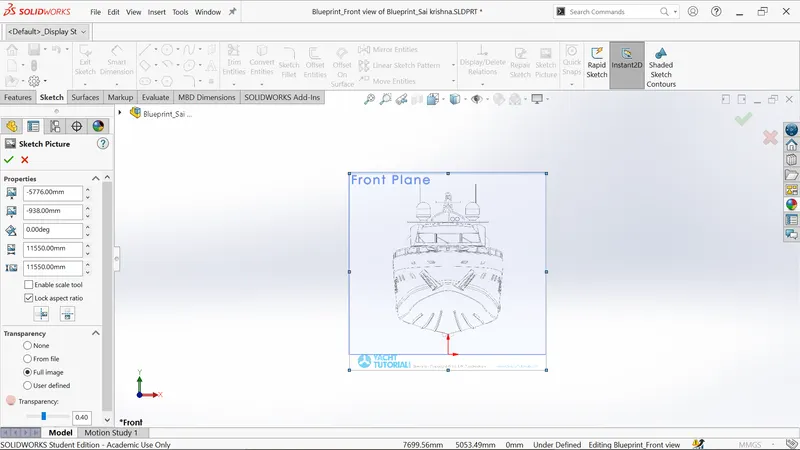
- Select the new sketch on front plane and insert the front view blueprint picture from the sketch tools.
- Change the name of sketch1 to Blueprint front view.
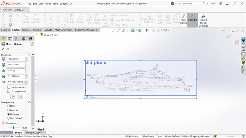
- Select the new sketch on right plane and insert the side view blueprint picture from the sketch tools.
- Change the name of right plane as mid plane.
- Change the name of sketch2 to Blueprint side view.
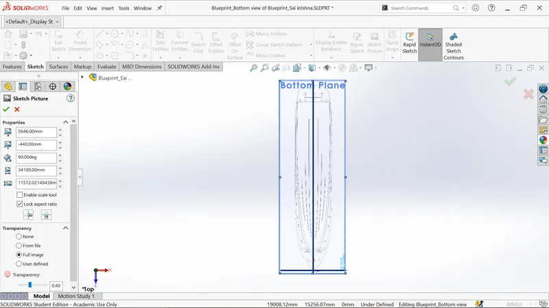
- Select the new sketch on top plane and insert the bottom view blueprint picture from the sketch tools.
- Change the name of top plane as bottom plane.
- Change the name of sketch3 to Blueprint bottom view.
- Create a new plane and as reference take the front plane with offset distance 32920mm.
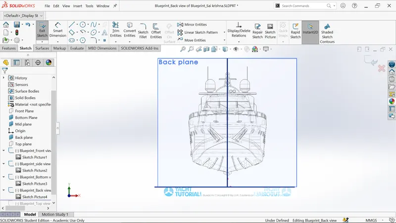
- Change the name of plane 1 as back plane.
- Create a new sketch on back plane and insert back view blueprint picture.
- Change the name of sketch4 to Blueprint back view.
- Create a new plane and as reference take the bottom plane with offset distance 10000mm.
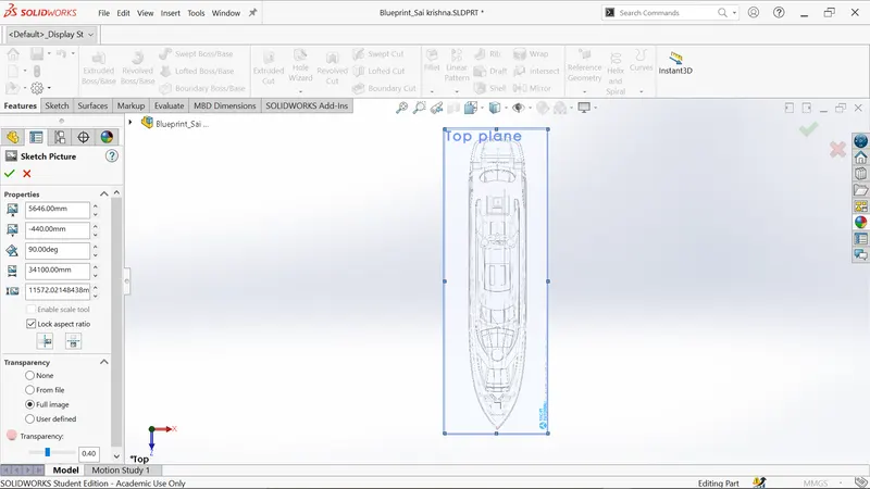
- Change the name of plane 2 as top plane.
- Create a new sketch on top plane and insert top view blueprint picture.
- Change the name of sketch5 as Blueprint topview.
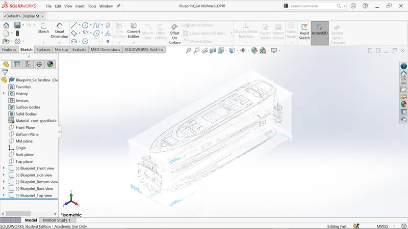
- Finally save the part model as blueprint set up.
Modelling of Propeller
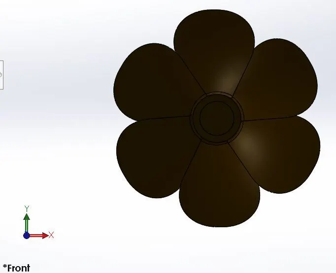
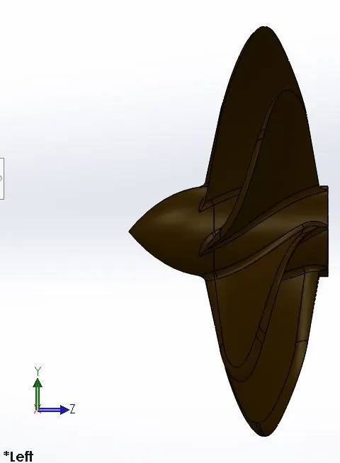
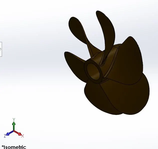
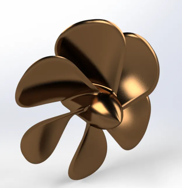
A propeller is a mechanical device consisting of revolving shaft with two or more broad angle blades that is used to propel the vehicle such as ships or airplanes.
Features used:
Sketch: Sketch creates 2D drawing for the model of having several entities like lines,spline,circles,rectangle etc.
Revolve:Used to create the revolve body by selecting centerline as axis.
Lofted Surface:Used to fill the gap between two curved surfaces.
Fillet:Used for creating smooth edges in order to avoid the sharp edges.
Cut extrude:Used to remove the material from extrude body.
Circular pattern:Creates a pattern around a circular path.
Procedure to be followed:
- Firstly open a new solidworks part with MMGS unit system.
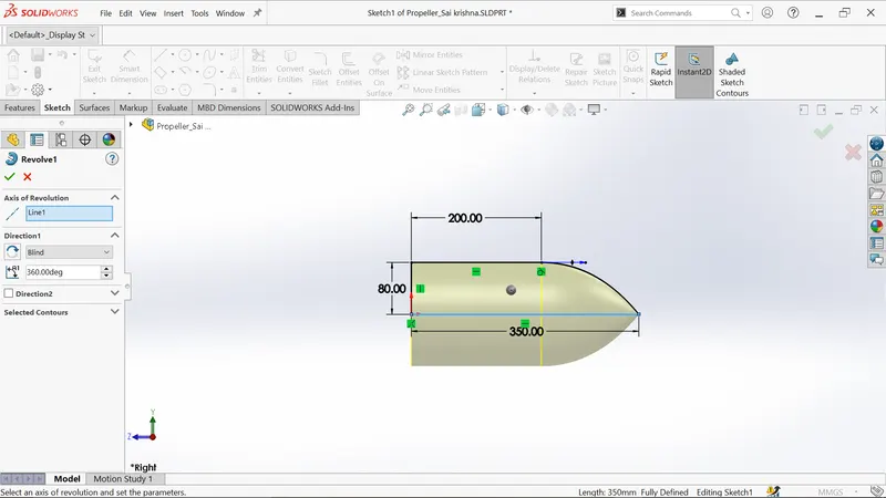
- Create a new sketch on right plane and draw the sketch as shown in below.
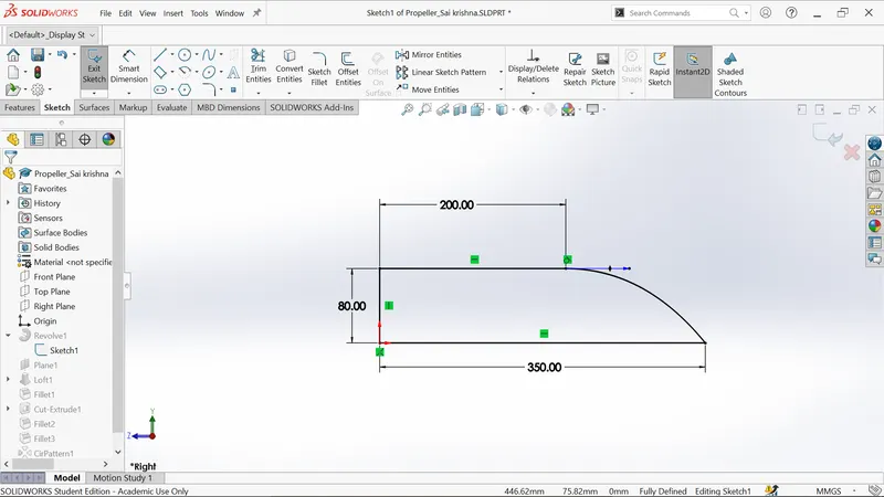
- Select the boss/base revolve and select blue line as axis to revolve as shown in picture.
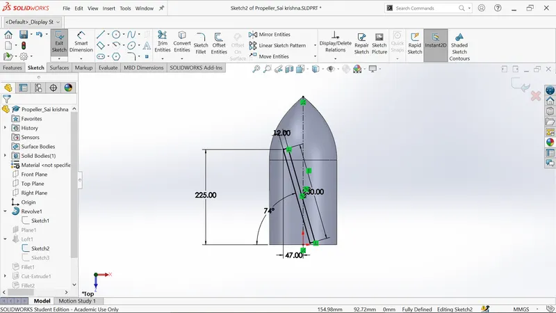
- Select the top plane and sketch and draw the rectangle .
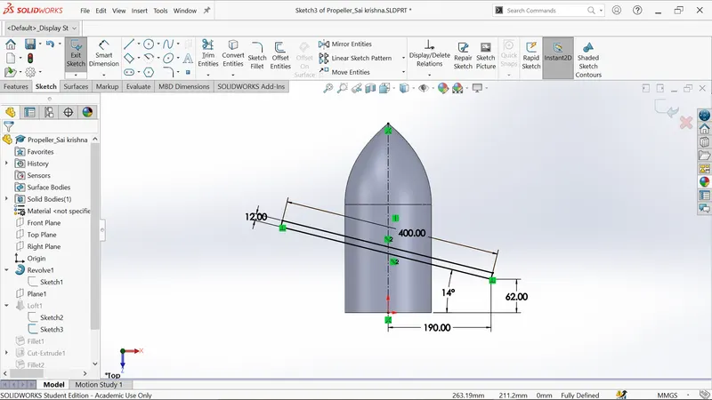
- Create a new plane with reference as top plane with offset distance 360 mm.
- Select the new plane and click sketch to draw the rectangle.
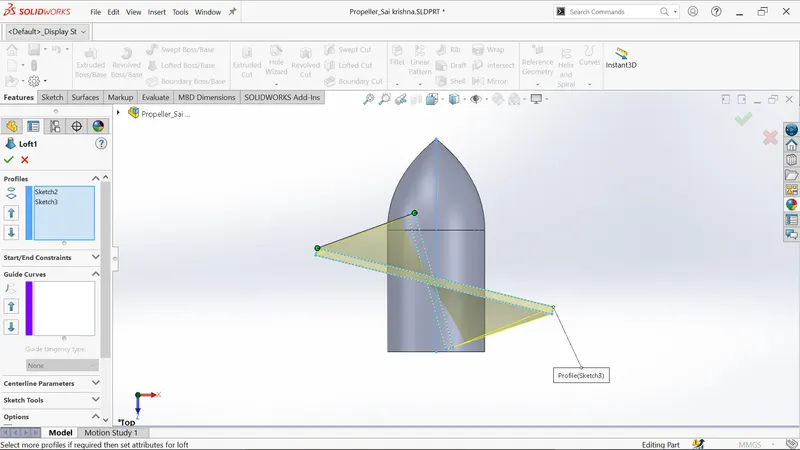
- Select boss/base loft and create a solid loft as shown below.
- Add the fillets for edges.
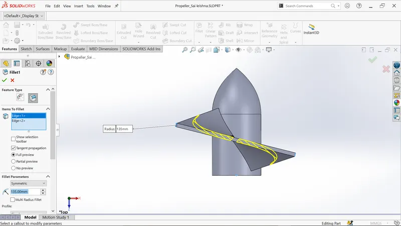
- Create the sketch on the surface and draw the circle as shown in picture.
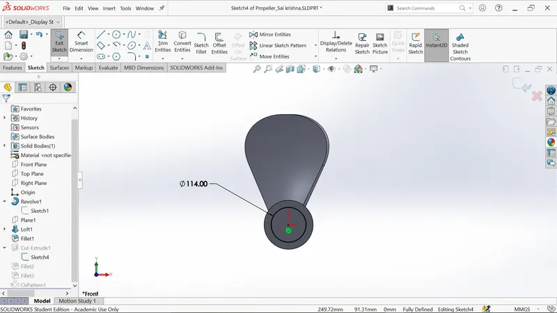
- Select cut extrude and extruded inwards as shown in below.
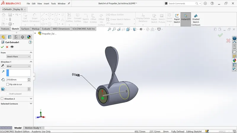
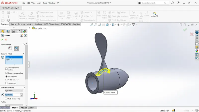
- Add the fillets for the four edges of loft.
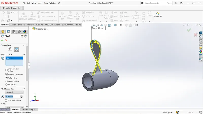
- Add the two fillets as shown below.
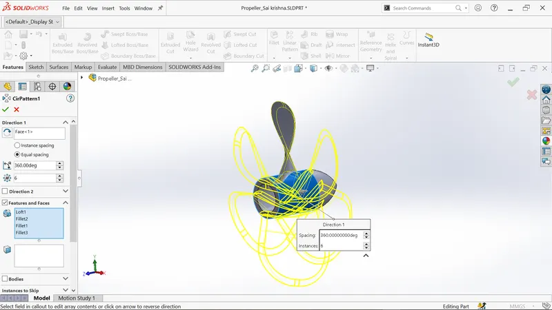
- Now use the circular pattern to create pattern of blades around the hub.
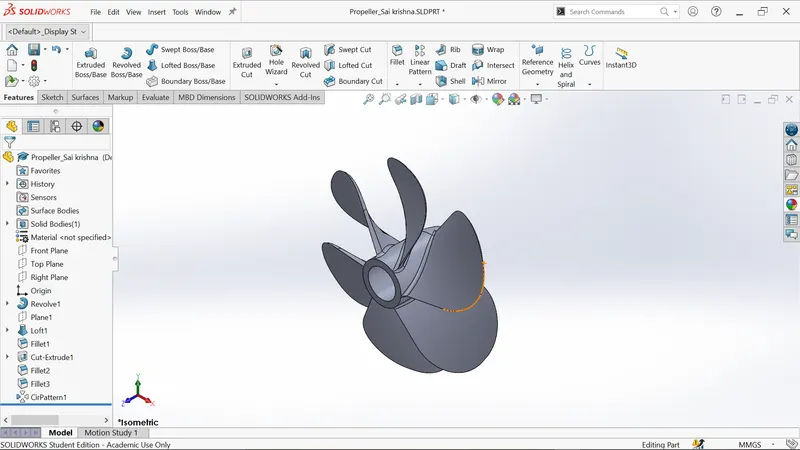
- Add the appearnce as shown below.
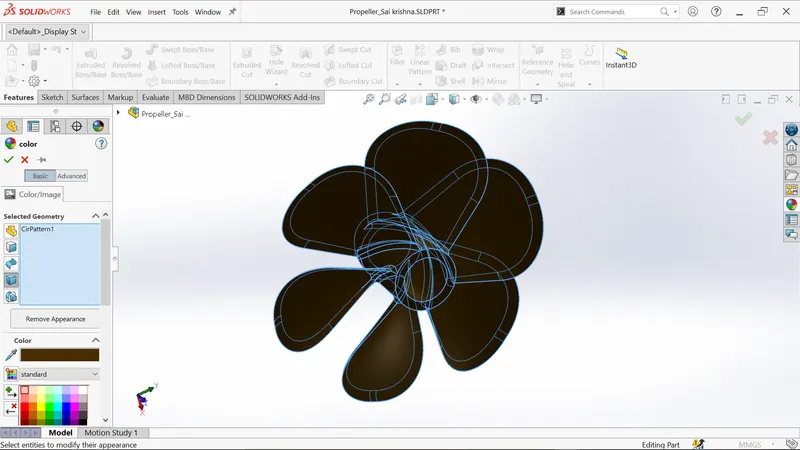
- Finally save the part model as Propeller.
Views of Propeller:
Front view:
Left view:
Isometric view:
Render image of propeller:
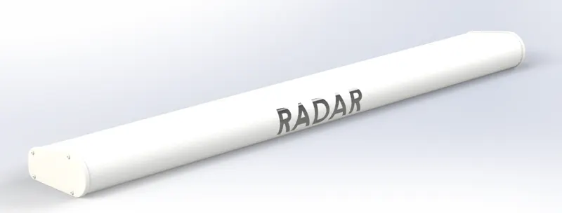
Modelling of Radar
A radar is a device used for detecting the surrounding objects with the help of radio waves.
Features used:
Sketch:Sketch creates 2D drawing for the model of having several entities like lines, splines,circles etc.
Boss extrude:Used to extrude 2D sketch into 3D body and it can be done in both forward and reverse directions.
Fillet:Used for creating smooth edges in order to avoid sharp edges.
Sketch pattern:Used to create the 2D pattern.
Mirror:This feature used to mirror the selected features or bodies.
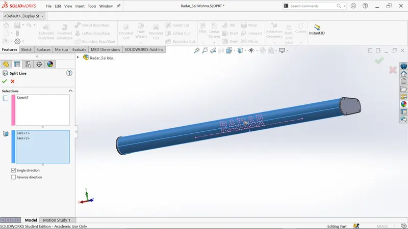
Split line:Used for projecting entities on planar or curved faces.
Procedure to be followed:
- Firstly open a new solidworks part with MMGS unit system.
- Create the new sketch on right plane and sketch as shown below.
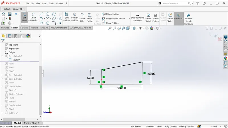
- Extrude the sketch with distance 700 mm.
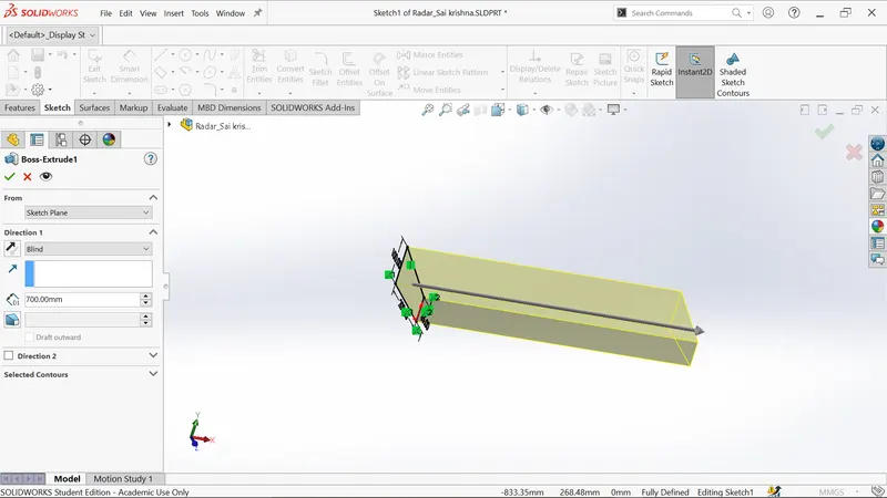
- Add the fillets as shown below.
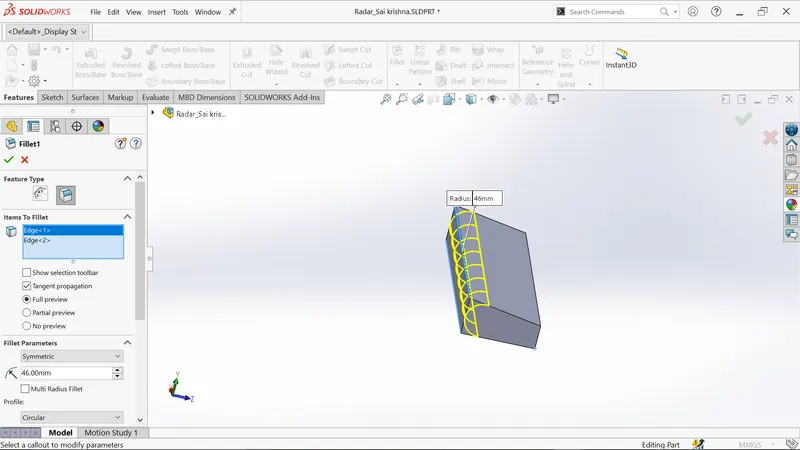
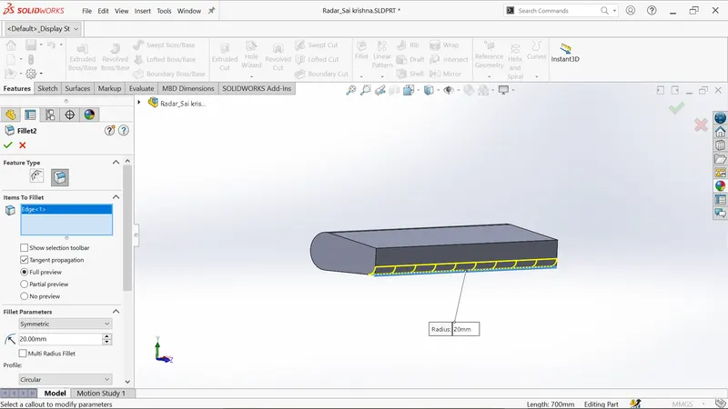
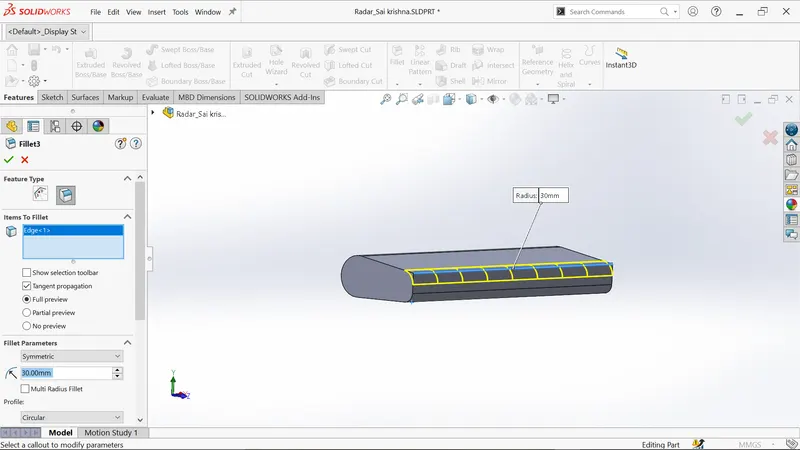
- Select the below surface and make the offset with 3 mm.
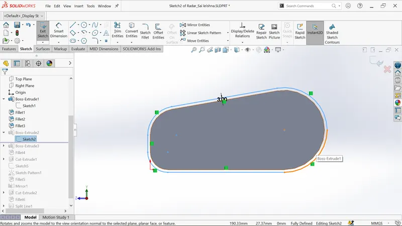
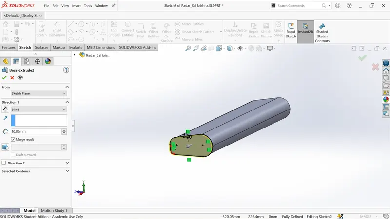
- Extrude with 10 mm.
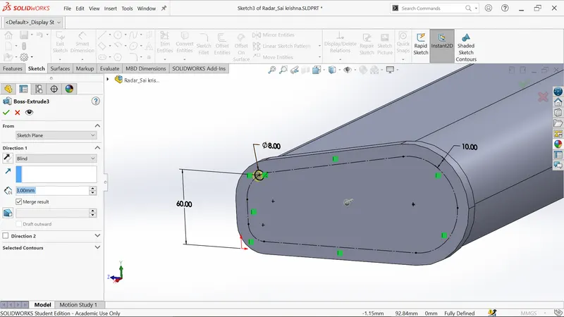
- Select the surface as shown below and draw the sketch as shown.
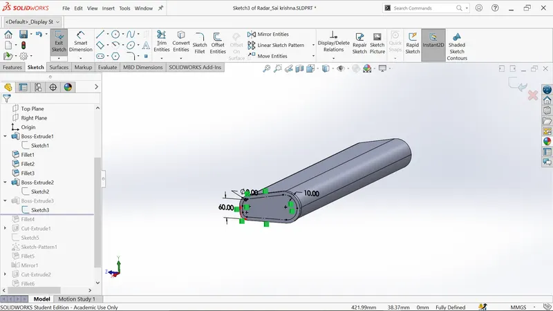
- Extrude with depth 3mm.
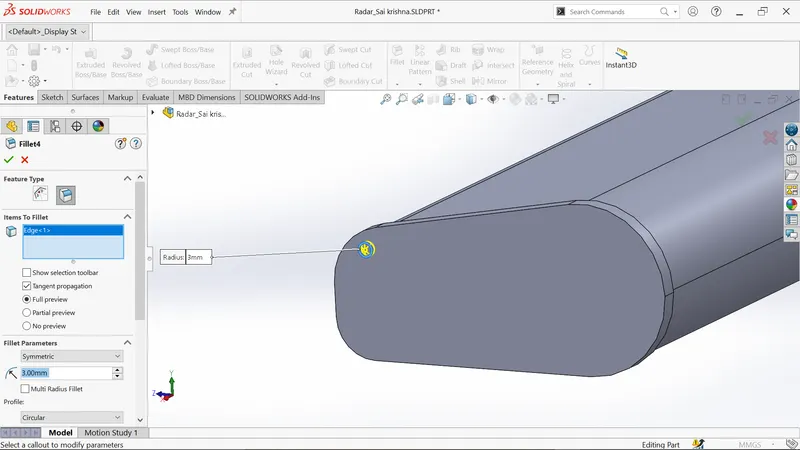
- Add the fillet for upper edge.
- Select the surface as shown below and draw the polygon.
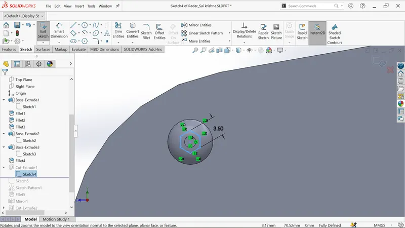
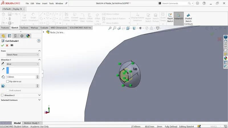
- Extrude with depth 1.5 mm.
- Select the surface as shown below and sketch the points with required dimensions as shown.
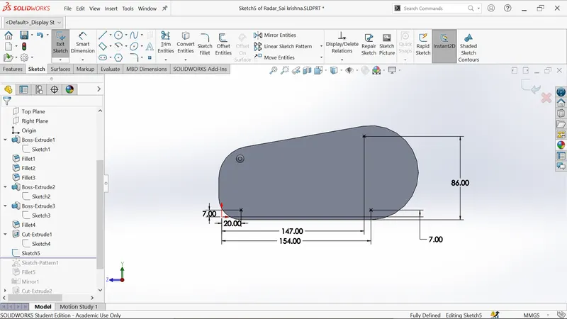
- Use the sketch drive pattern as shown below.
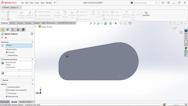
- Add the fillets for edges.
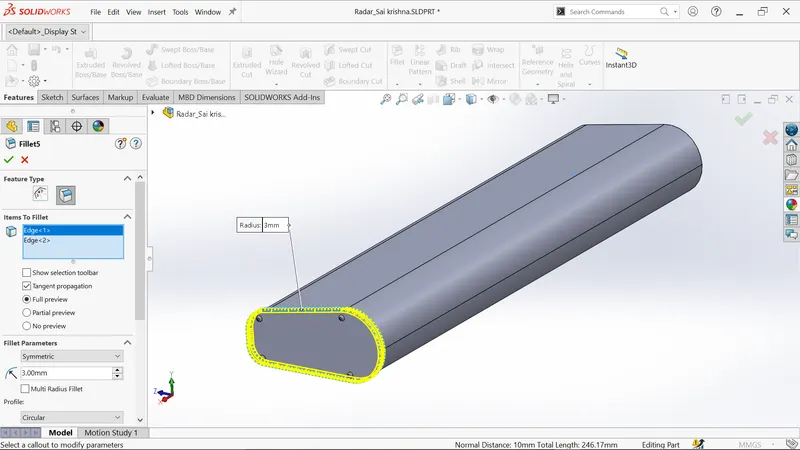
- Mirror the body.
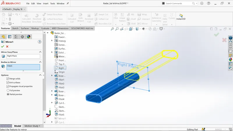
- Draw the circle on the surface with required dimensions as shown below.
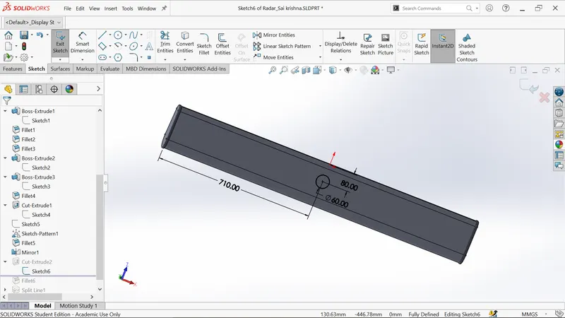
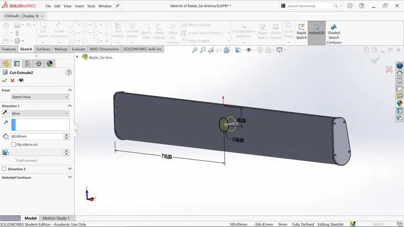
- Extrude cut inwards with 40 mm.
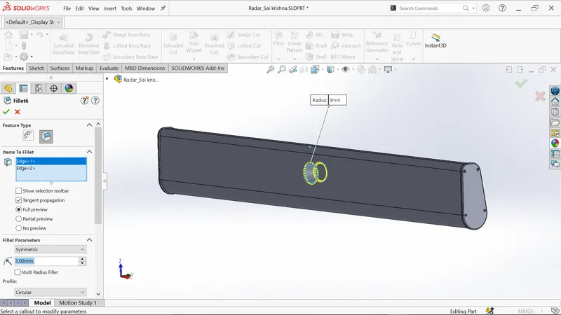
- Add the fillets for edges.
- Create the sketch on surface as per dimensions and add the text as shon below.
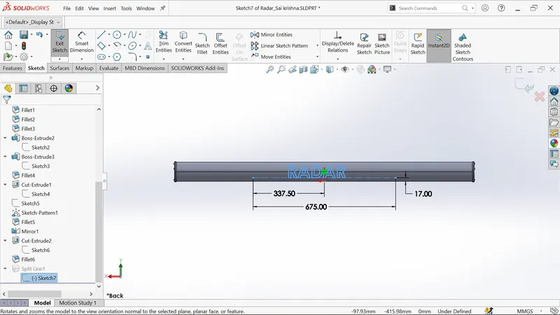
- Now use the split line feature for splitting the text from the surface.
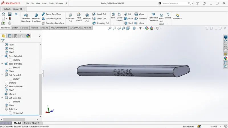
- Chane the appearance for the radar.
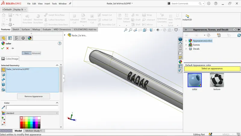
- Chane the appearance for the text.
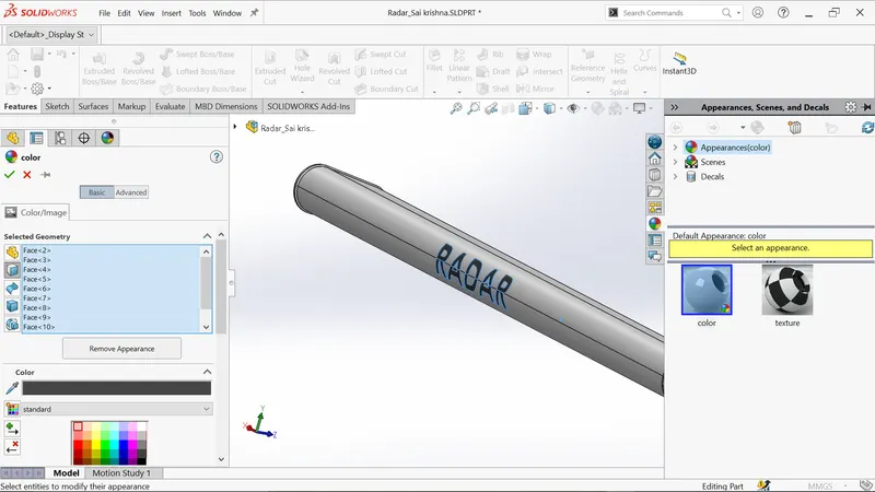
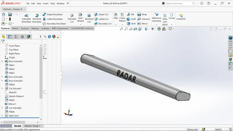
- Finally save the part model as Radar.
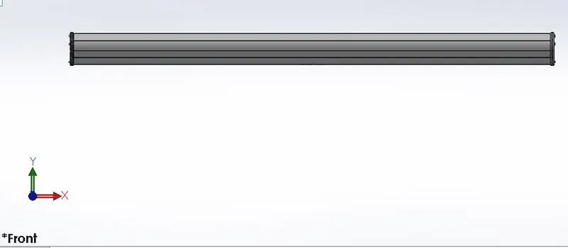
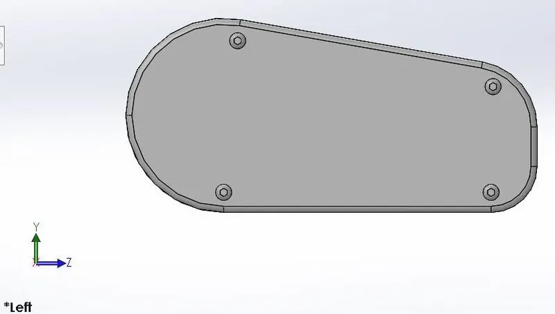
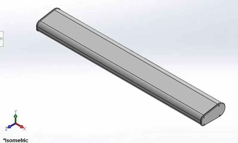
Views of Radar:
Front view:
Right view:
Isometric view:
Render image of Radar:
Modelling of Hull
A hull is watertight body of the ship of having the deck surface at top in which all the other parts of ship like superstructure,seats ,anchor are incorporated on it.
Features used:
Sketch:Sketch creates 2D drawing for the model of having several entities like lines, splines,circles etc.
Project Curve:Used to project the two sketches into single curve.
Lofted Surface:Used to fill gap between two curved surfaces.
Trim Surface:Used to trim selected surfaces by trim tool.
Knit surface:Used to combine the multiple surfaces into single surface.
Filled Surfcae:This feature used to fill the the surface material in between two surfaces.
Shell:Shell feature is used for defining the thickness of thick and thin materials.
Boss Extrude:Used to extrude 2D sketch into 3D body and it can be done in both forward and reverse directions.
Cut Extrude:Used to remove the material from extrude body.
Fillet:Used for creating smooth edges in order to avoid sharp edges.
Chamfer:Used for creating the sloping surfaces at the edges.
Sweep:It is used to make extrude body for sweeping curves.
Revolve:Used to create revolve body by selecting centerline as axis.
Dome:Use to create concave shape on the surface.
Helix/spiral:Used to create helical profile around the selected feature.
Linear pattern:Used to pattern the 2D sketch in linear direction.
Delete Face:Used to delete the selected faces.
Body-Delete/Keep:Used to delete or keep the selected bodies from the model.
Split Line:Used for projecting entities on planar or curved surfaces.
3D sketch:Used to draw the sketch entities in 3D environment.
Procedure to be followed:
- Firstly open the blueprint set up file and save the file as Hull.
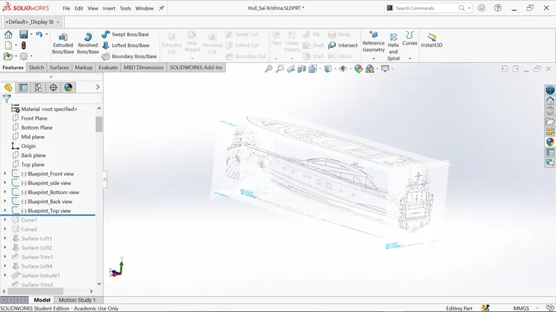
- Select the bottom plane and sketch and draw the line,spline with dimensions as shown below
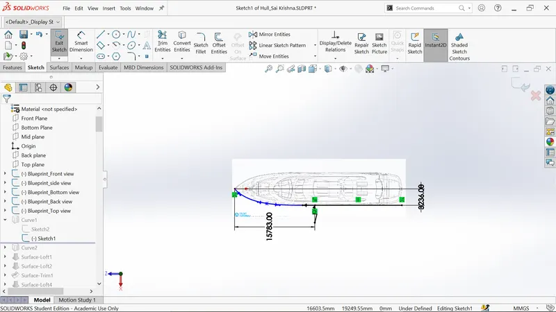
- Draw the sketch on the midplane (LINE AND SPLINE)as shown below.
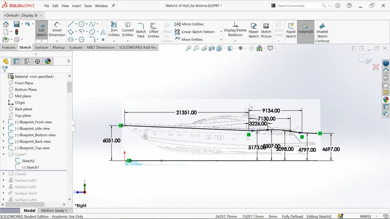
- Use the project curve feature to project the sketch1 and sketch2.

- Sketch on the midplane as shown below.
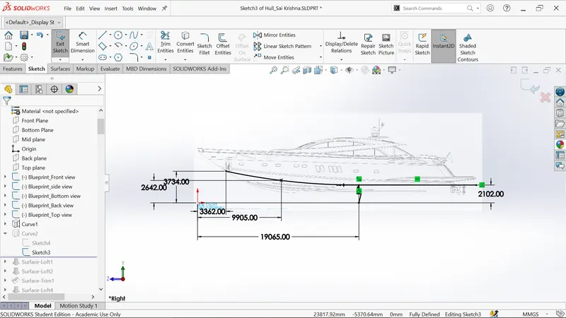
- Sketch on the bottom plane as shown below.
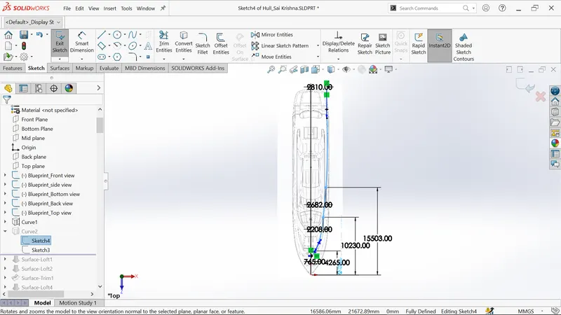
- Project the sketch3 and sketch4 using project curve feature.
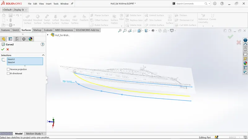
- select back plane sketch and draw spline coonecting with curve 1 and curve 2.
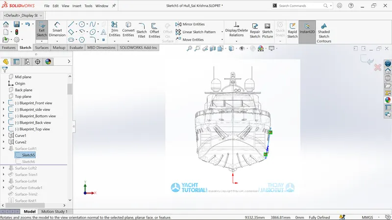
- Create sketch on midplane and draw the straight line and connect with front of curve 1 and curve 2.
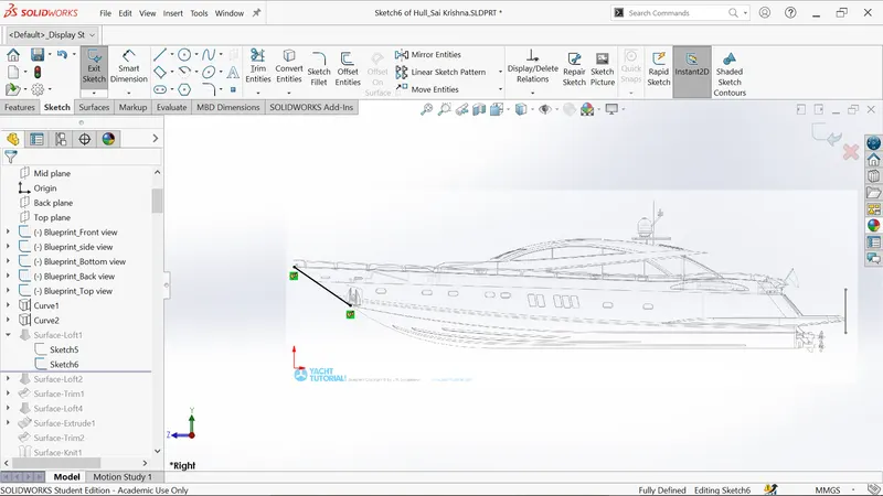
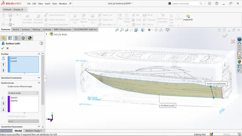
- Use surface loft feature for creating the loft between curve 1 and curve2.
- Click on sketch of midplane and draw as shown below.
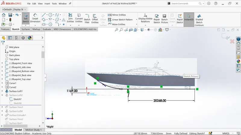
- Select back plane and sketch and draw the the spline connecting surface loft1 and previous sketch.
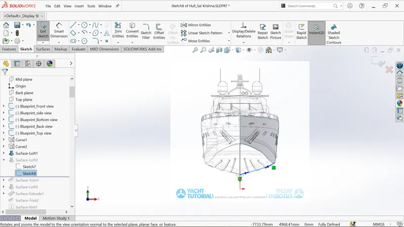
- Use surface loft feature for creating the loft at lower portion.
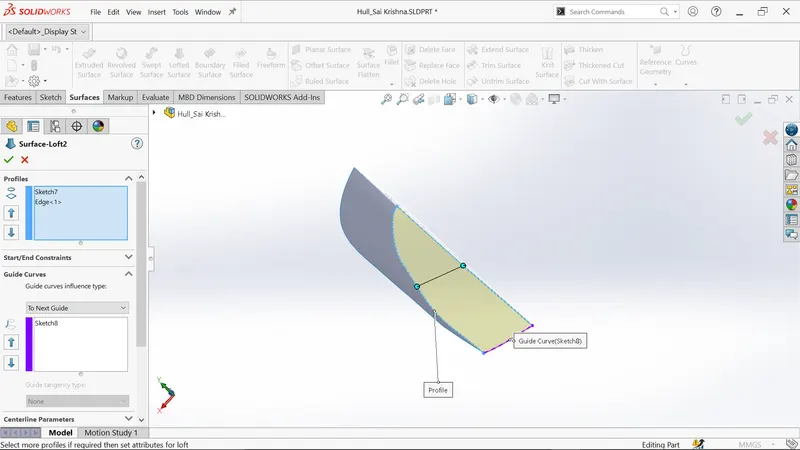
- Click on sketch of midplane and draw as shown below.
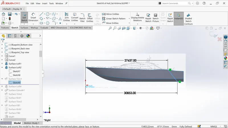
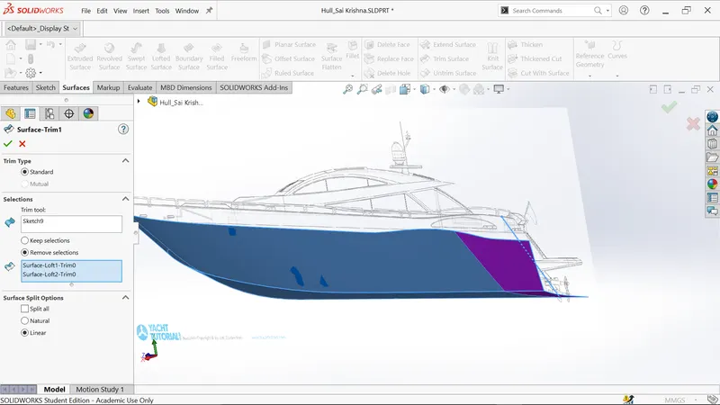
- Trim the unnecessary surface of purple area.
- Click on sketch of midplane and draw as shown below.
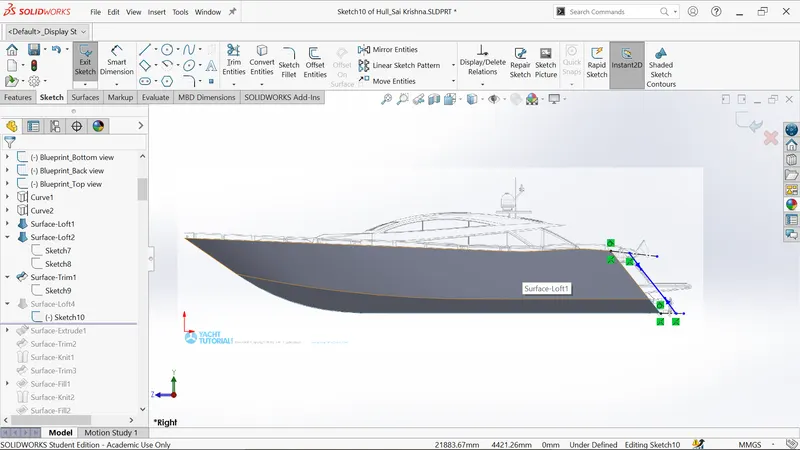
- Now create the loft surface as shown below
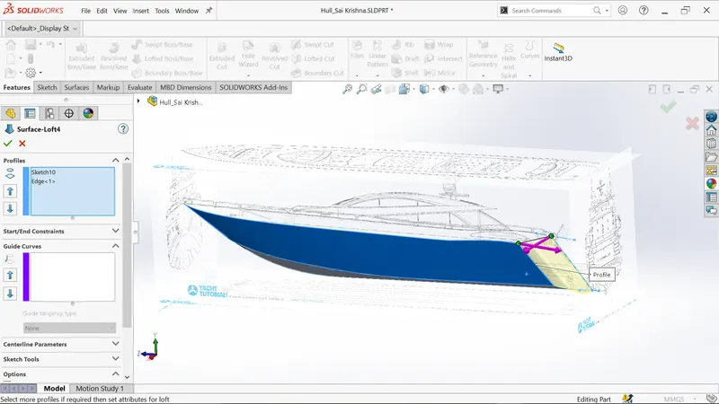
- Create the sketch on midplane as per the dimensions.
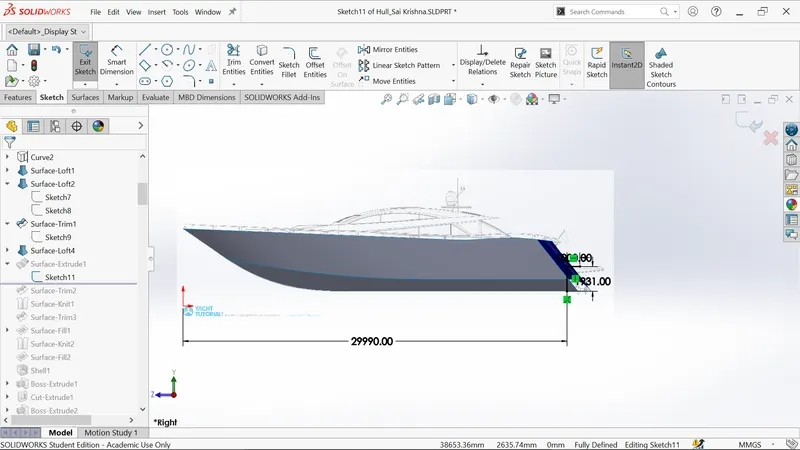
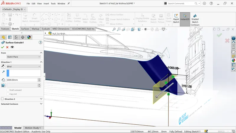
- Click surface extrude and extrude outwards as shown.
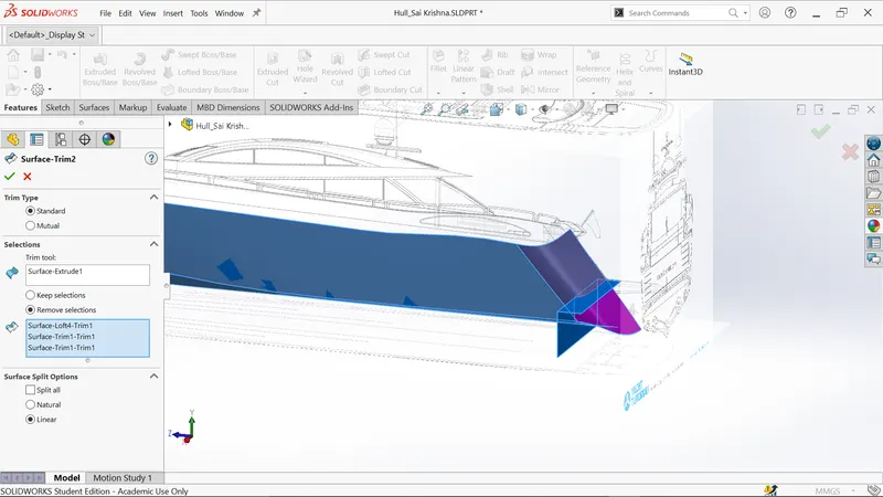
- Trim the purple surface.
- Knit the Surfaces as shown.
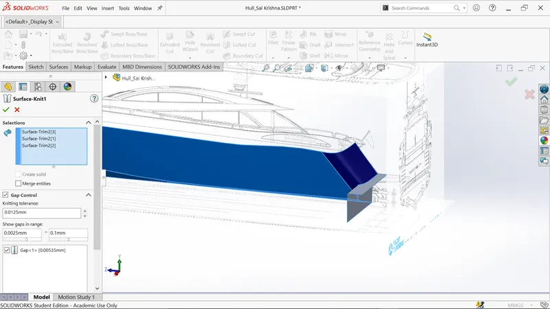
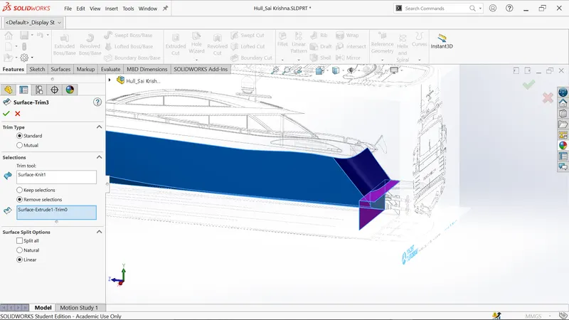
- Trim the purple surface.
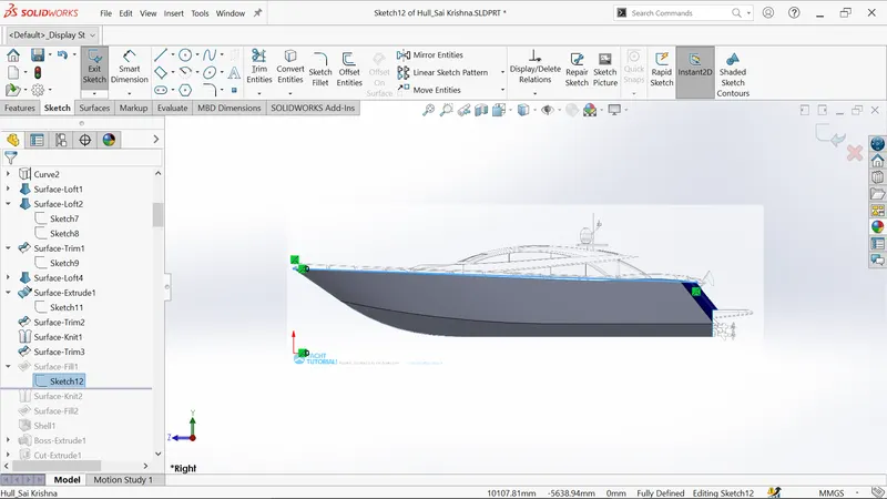
- Select midplane and click sketch and draw the straight line.
- Fill the surface using the surface fill feature.
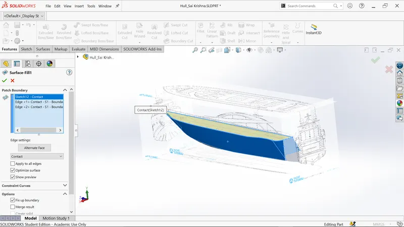
- Knit the blue surfaces as shown below.
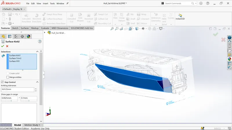
- Fill the surfaces using surface fill.
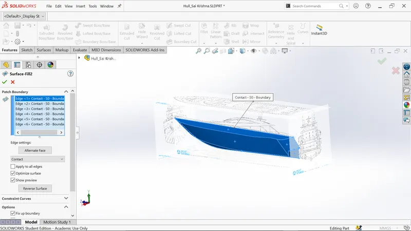
- Create shell with thickness 120 mm.
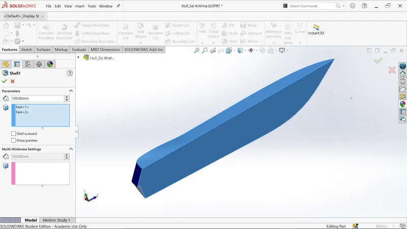
- Select midplane and click sketch and create profile by making offset with 50 mm and trim unnecessary lines.
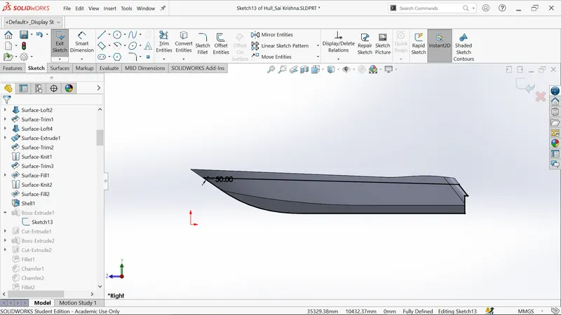
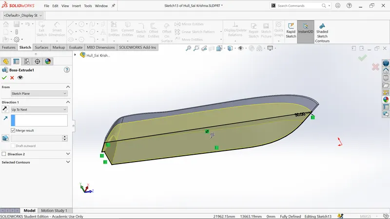
- Use boss extrude to extrude upto shell by selecting upto next.
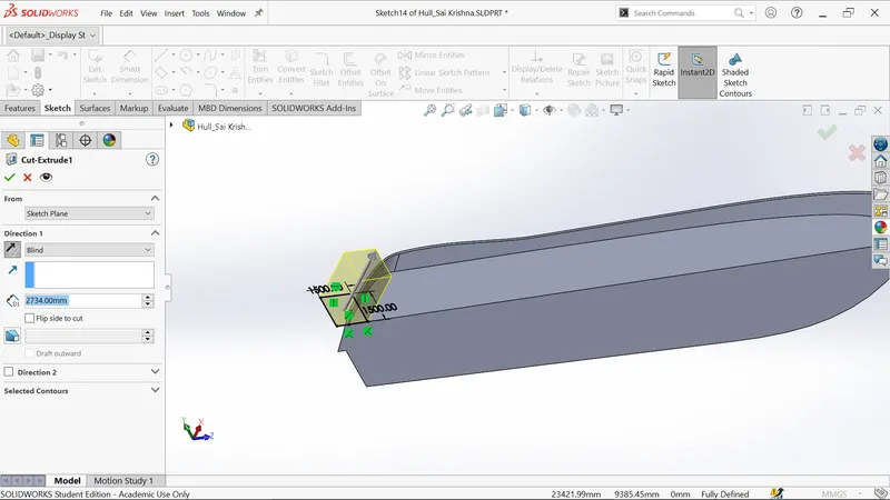
- Create the sketch on midplane and extrude with depth 2734 mm as shown below.
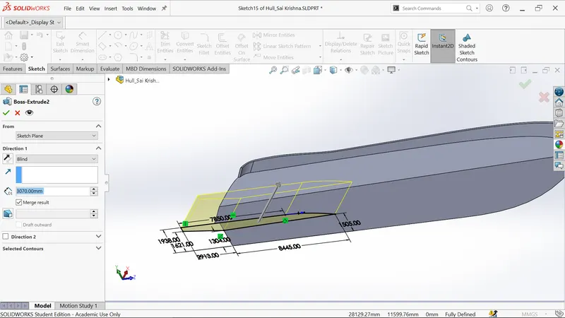
- Create the sketch on midplane and extrude with depth 3070 mm as shown below.
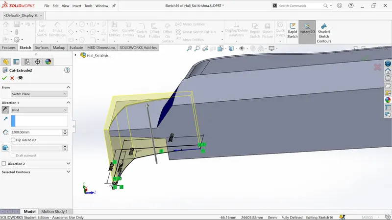
- Create the sketch on bottom plane and extrude with depth 3200 mm as shown below.
- Add the fillet for the edge.
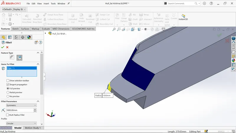
- Apply the chamfer with angle distance as shown below.
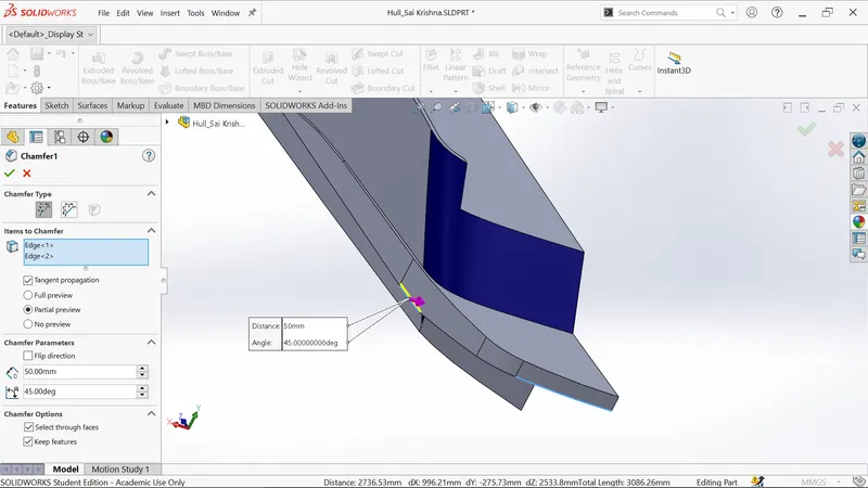
- Apply the chamfer with distance distance option as shown below.
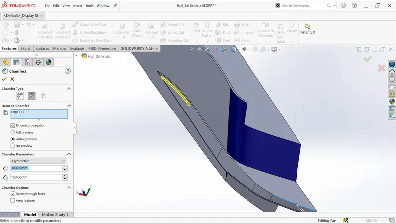
- Apply the fillet for the following edges.
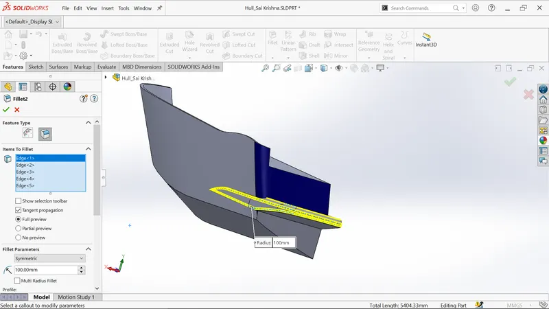
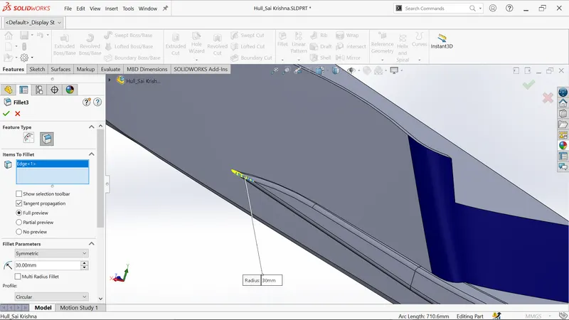
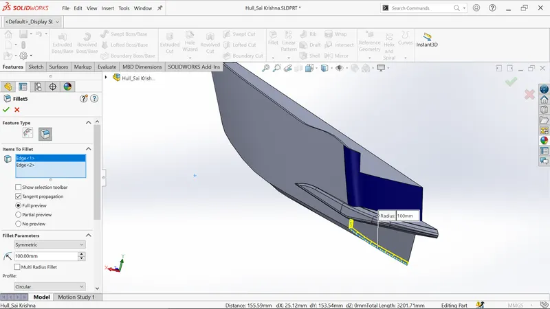
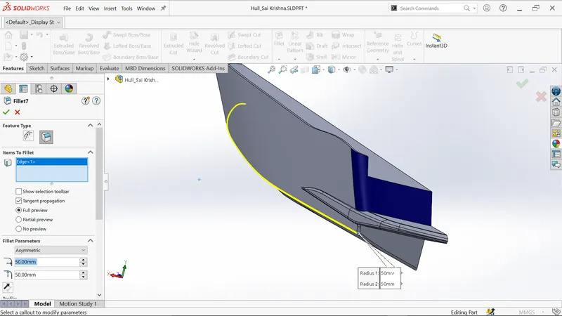
- Create new plane 1 with reference as midplane with offset 5000mm.
- Create the sketch on plane1 and extrude cut with depth 38 mm as shown below.
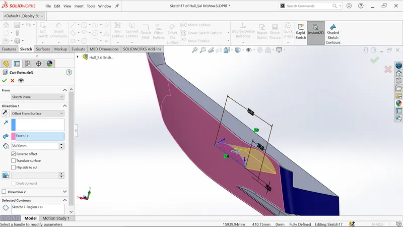
- Apply the fillet for the following edges.
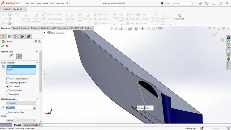
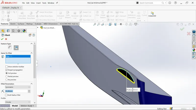
- Create the sketch on plane1 for windows profile and draw sketch as per dimensions and extrude cut with depth 50 mm as shown below.
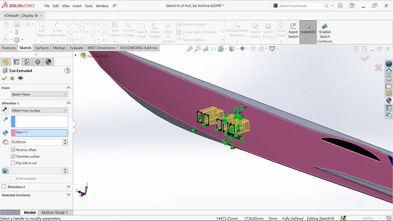
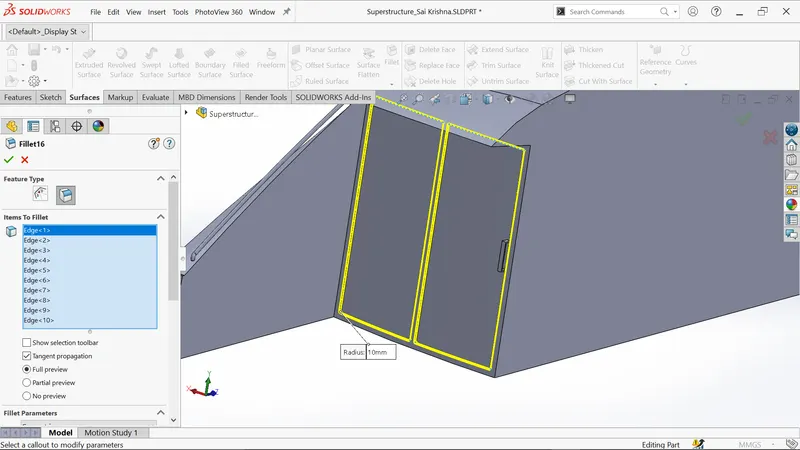
- Apply the fillet for all edges.
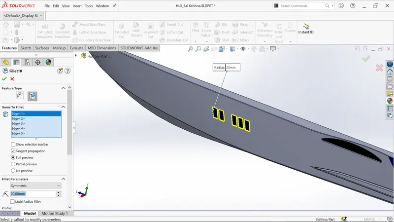
- Create the sketch on plane1 for portholes and draw sketch using straight slots as per dimensions and perform extrude cut with depth 50 mm as shown below.
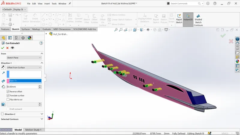
- Create the new plane2 as show below.
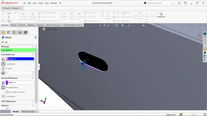
- Create the sketch on plane2 and draw circle with diameter 40 mm.
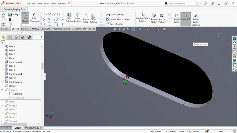
- Select 3D sketch and convert the edge as shown below.
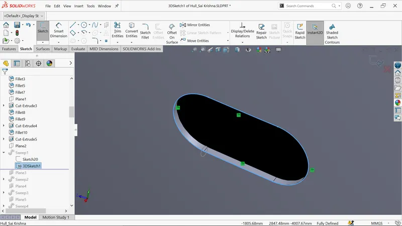
- Perform sweep feature for obtaining the sweep for port hole.
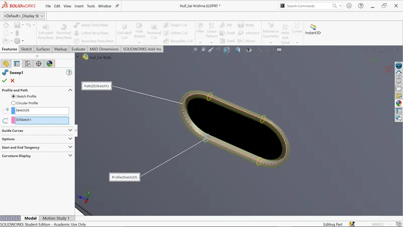
- Repeat same procedure for all the portholes.
- Create the sketch on plane1 for cable hole and cut extrude as shown below.
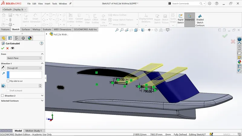
- Create the new plane as shown below.
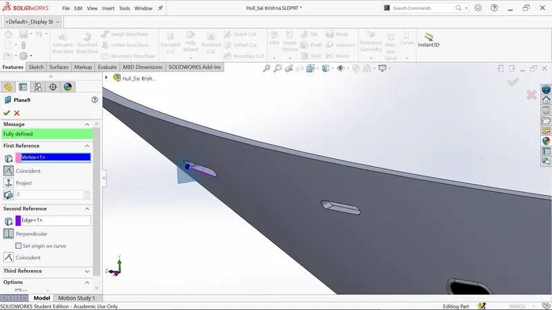
- Create the sketch on new plane and draw circle 25mm diameter.
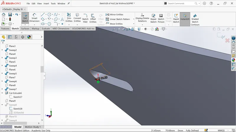
- Create the 3D sketch and convert the edge as shown.
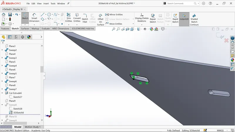
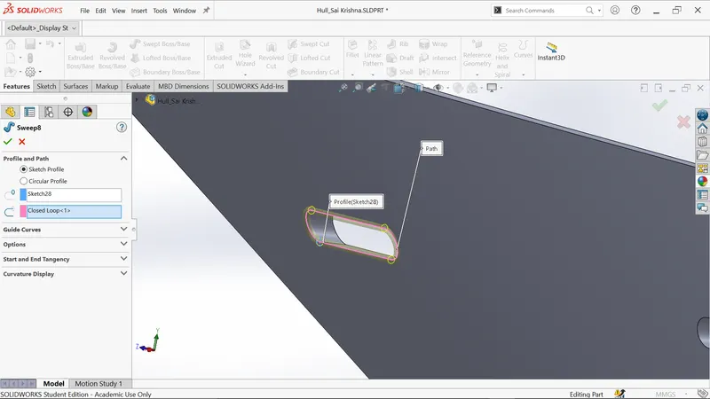
- Create the sweep by using sweep feature.
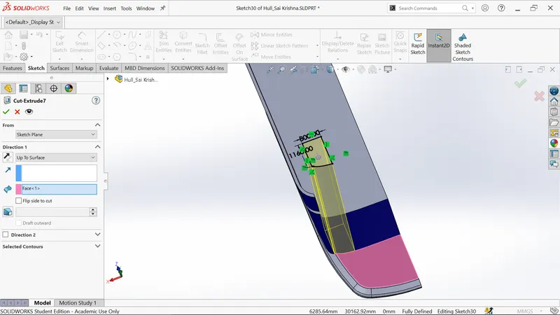
- Create the sketch on top plane as shown and extrude cut upto surface as shown below.
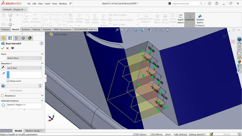
- Create the sketch for steps on the surface as per dimensions and extrude upto next as shown below.
- Create sketch on the same surface and extrude upto surface.
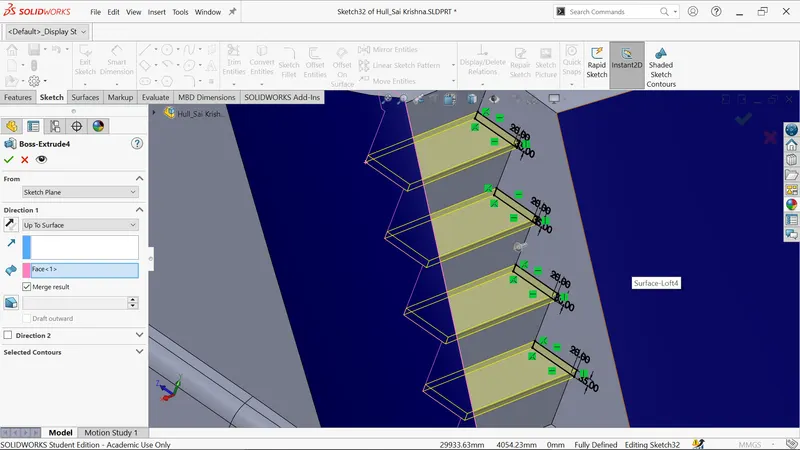
- Create the sketch on the surface as per dimensions and extrude with depth 10 mm.
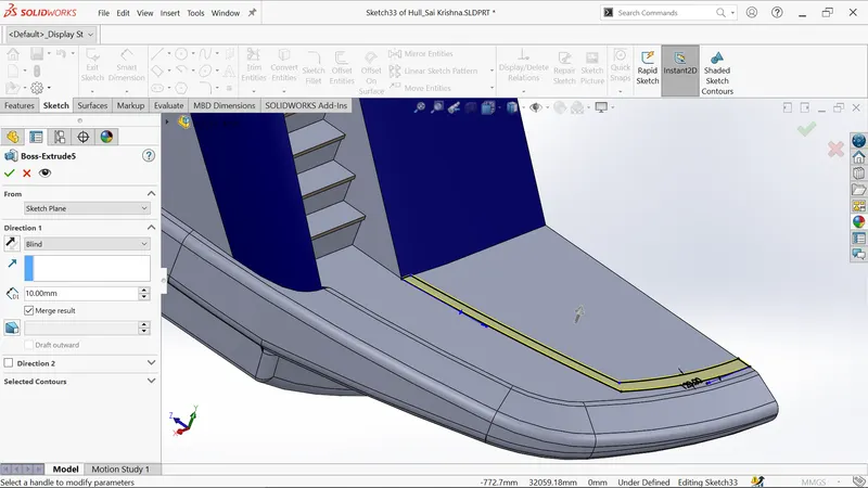
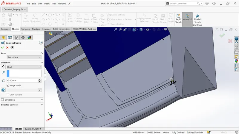
- Select before extrude surface and draw lines and trim unnecessary lines for make rectangle and extrude upto 10mm.
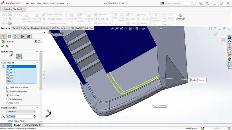
- Apply the fillet of 10m radius.
- Sketch on top surface and extrude as shown.
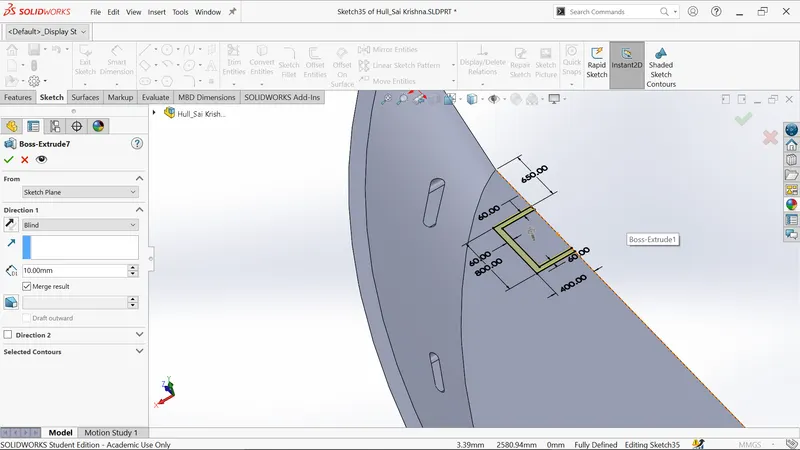
- Create the new plane as shown.
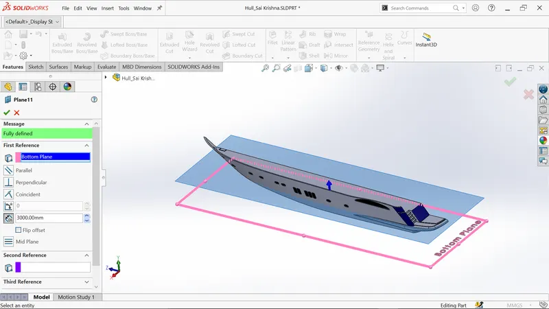
- Sketch on new plane and draw splines with offset and extrude upto surface.
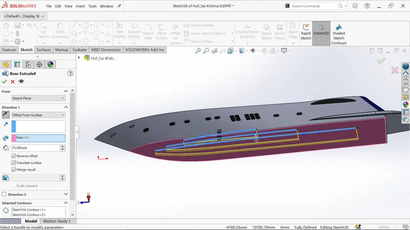
- Sketch on top surface and extrude as shown.
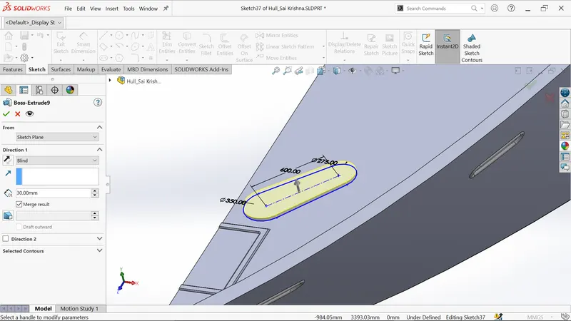
- Create the new plane as shown.
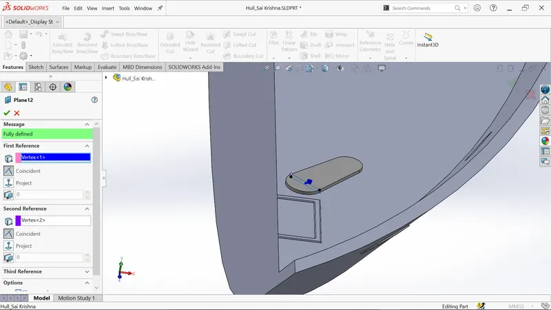
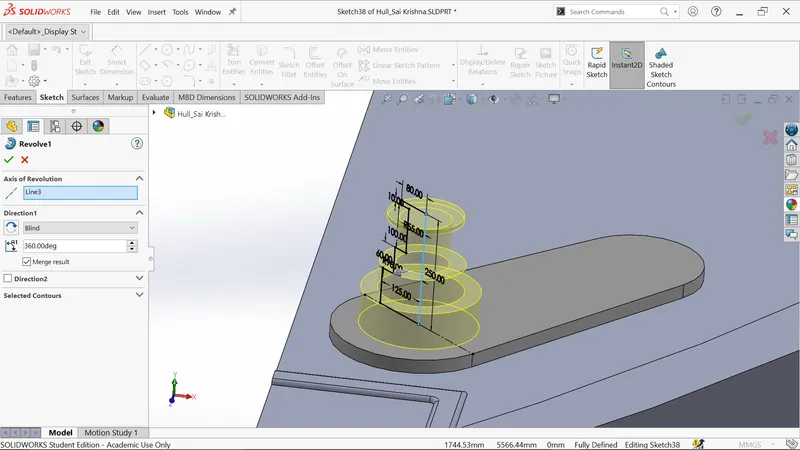
- Sketch on new plane and revolve by selecting blue line as axis.
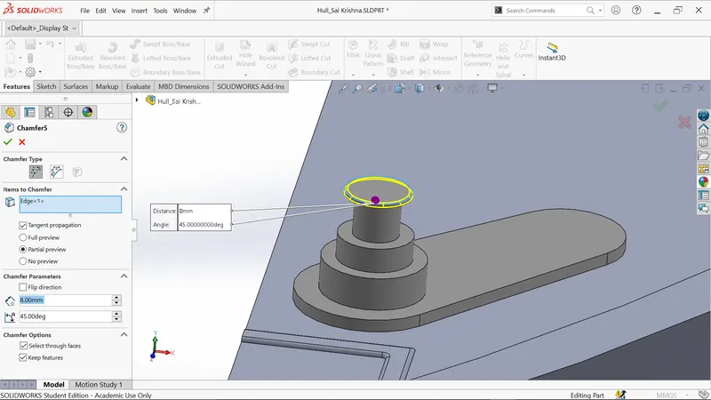
- Apply the fillet at outer edge.
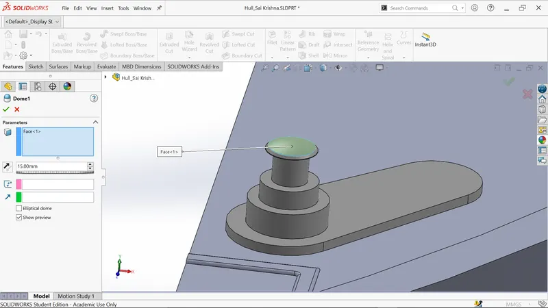
- Apply the dome at outer surface.
- Create the new plane as shown below.
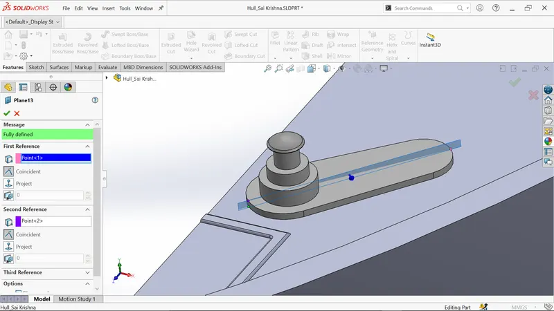
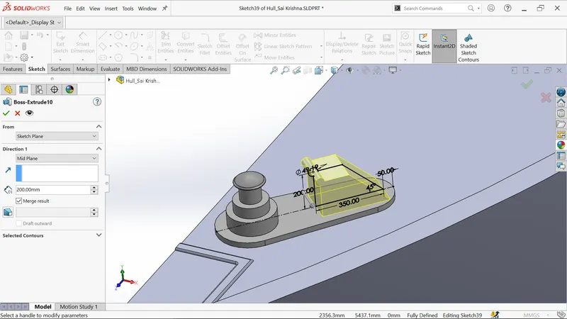
- Sketch on new plane as per dimensions and extrude as shown.
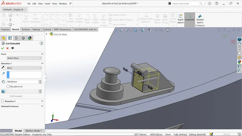
- Select the surface and sketch and extrude cut with 180 mm.
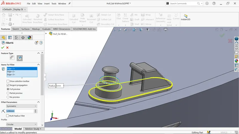
- Apply the fillet for all edges.
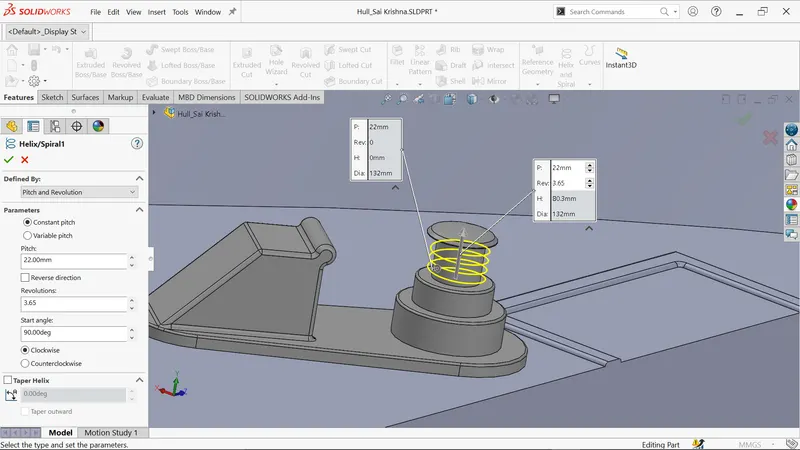
- Select the suface,click sketch and convert the edge and made helix profile.
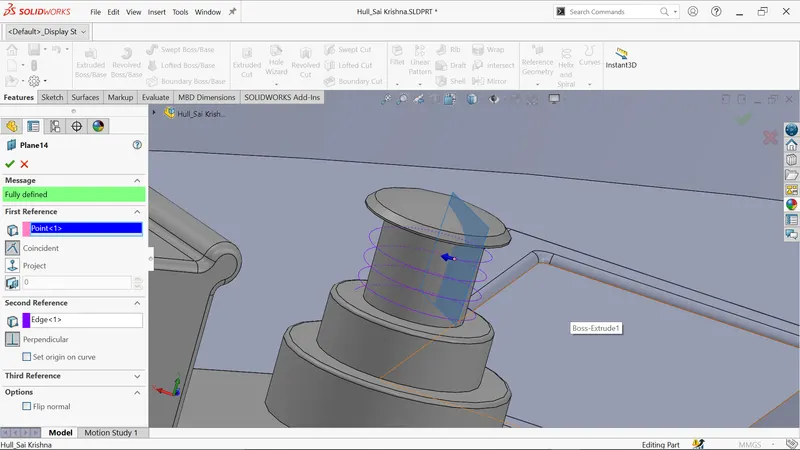
- Create the new plane as shown.
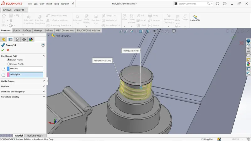
- Sketch on new plane and draw circle of 20 mm and perform sweep.
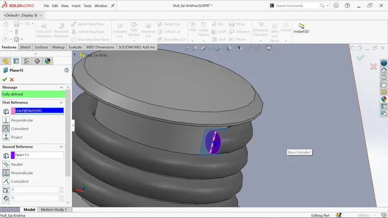
- Selectt outer surface of sweep and sketch and convert the edge.
- Create the new plane as shown.
- Sketch on new plane of taking spline and perform the sweep as shown.
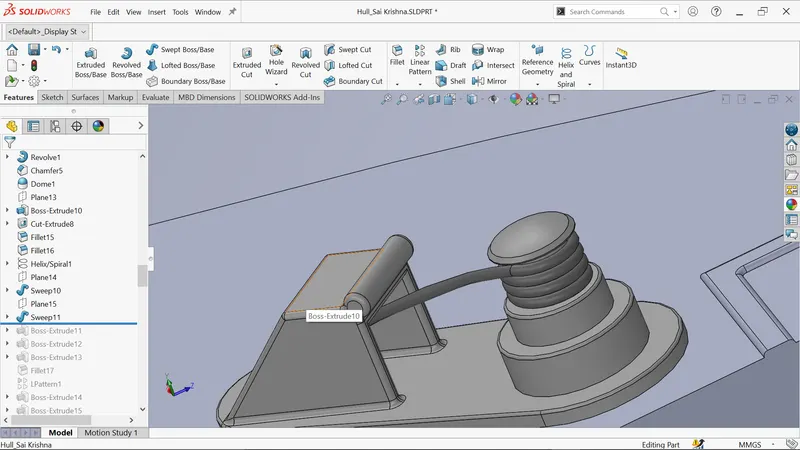
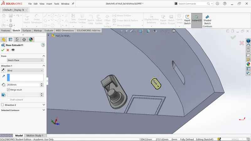
- Sketch on top surface for port hole using straight slot on top and extrude as shown.
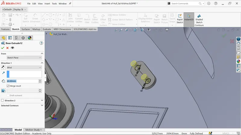
- Select top surface of porthole and sketch and perform an extrude as shown.
- Select top surface of porthole and sketch and perform an extrude as shown.
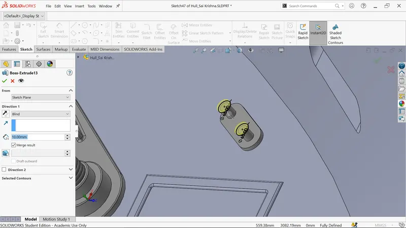
- Apply the fillet of 5mm.
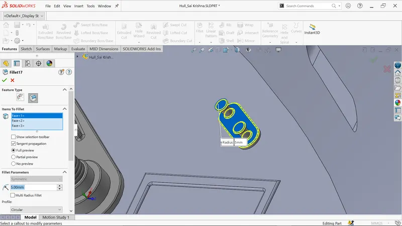
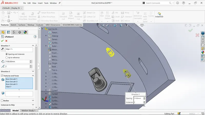
- Pattern the porthole as shown.
- Select top surface of hull and create sketch as per dimensions and extrude as shown below.
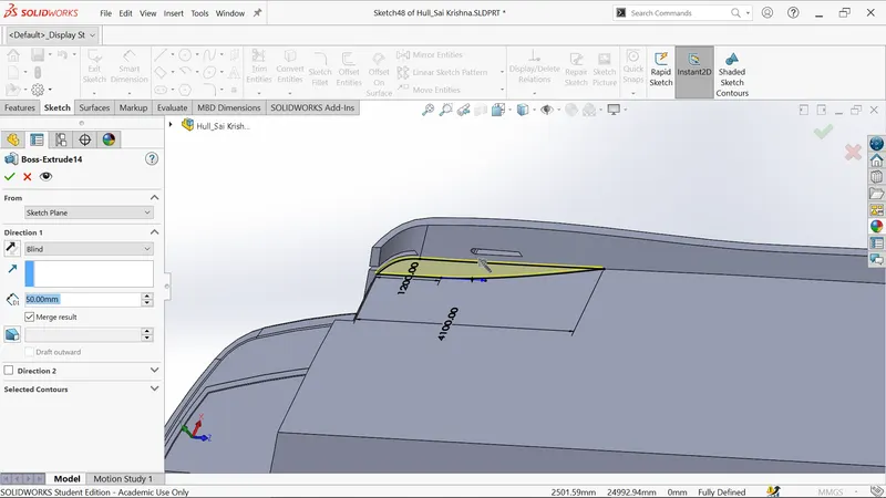
- Select the surface of before extrude body and sketch using straight slot and extrude as shown below.
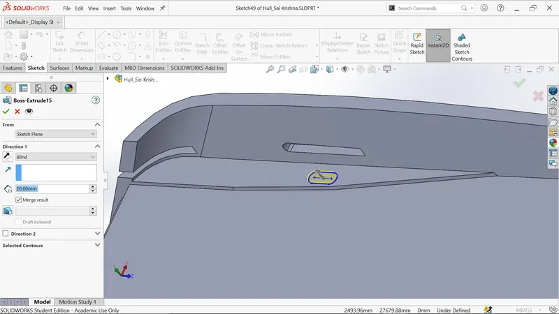
- Select top surface of porthole and sketch and perform an extrude as shown.
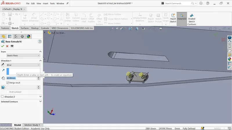
- Select top surface of porthole and sketch and perform an extrude as shown.
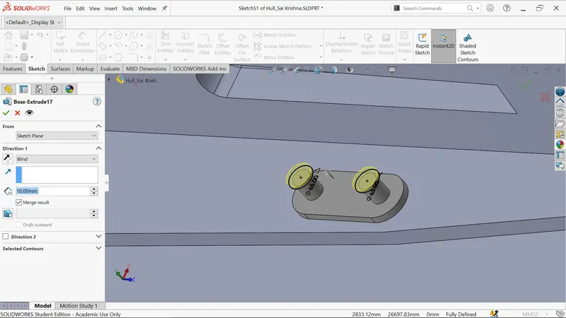
- Apply the fillets of 5mm.
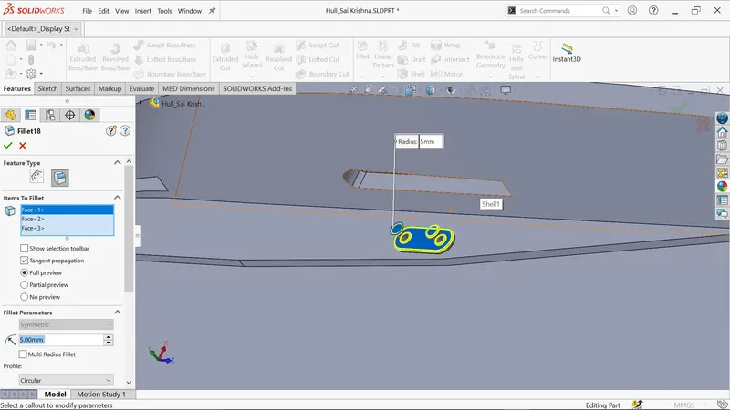
- Pattern the porthole as shown.
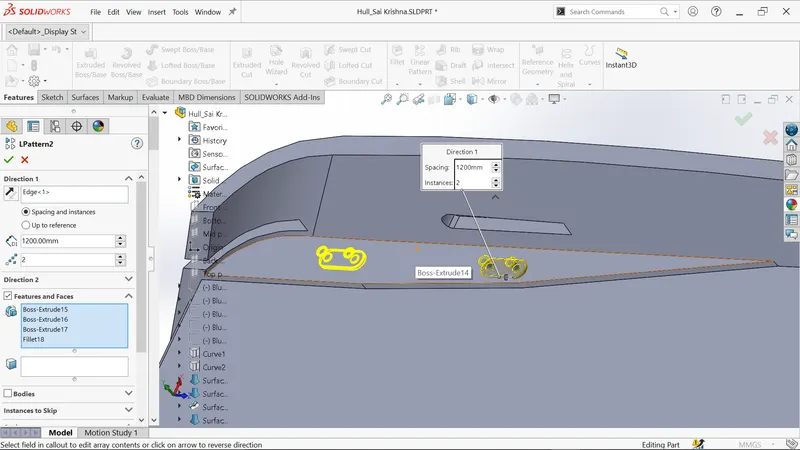
- Create the 2D sketch on surface as per dimensions and extrude upto next.
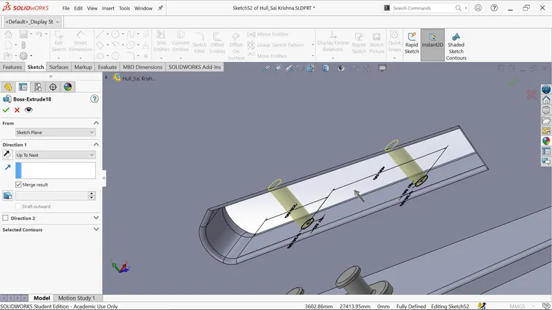
- Create the 2D sketch on surface as per dimensions and extrude upto next.
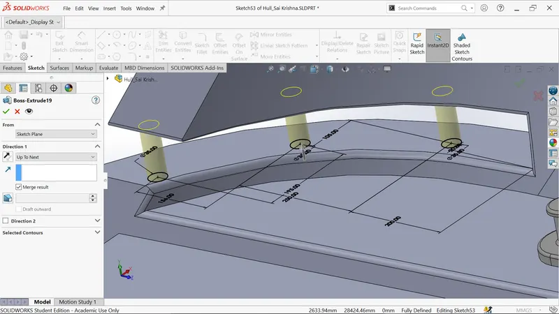
- Create the new plane as shown below.
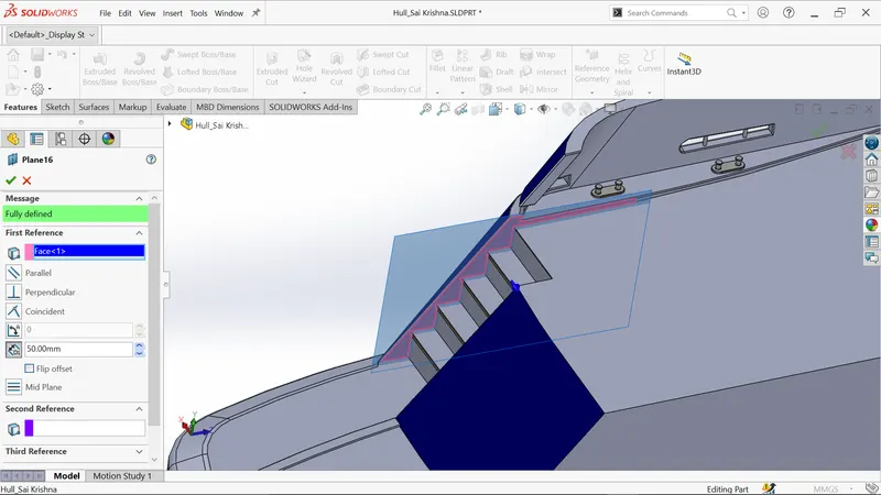
- Sketch on new plane and draw thw rectangle at end and exit sketch.
- Create the new plane as shown below and sketch the circle 30 mm on new plane.
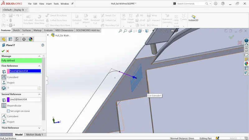
- Peform the sweep as shown below.
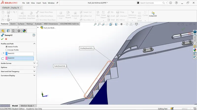
- Create the sketch on midplane.
- Offset the top edge of hull with 70 mm.
- Make the rail reference by taking lines and trim unnecessary lines as shown below and exit sketch.
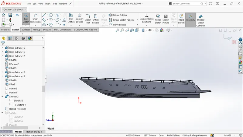
- Create the sketch on midplane.
- Convert the railing reference edge.
- Apply the sketch fillets for corners with 60 mm .
- Do this for all corners and exit sketch.
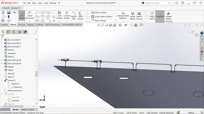
- Create a new sketch on plane11.
- Offset the two upper edges of hull ad exit from sketch.
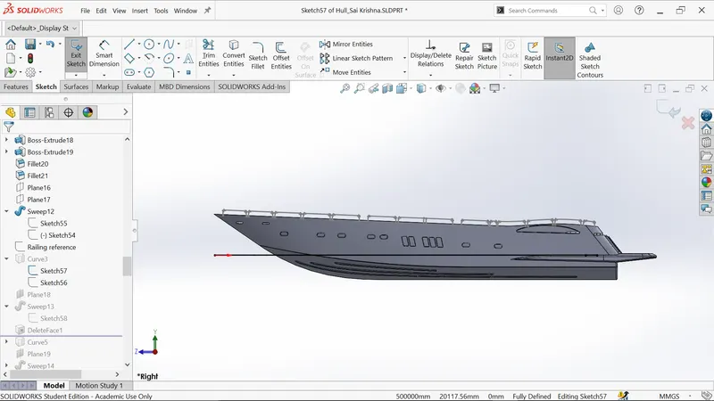
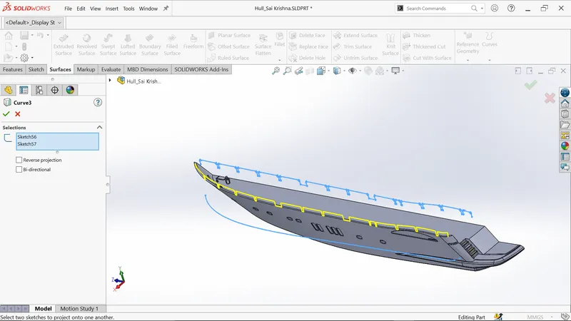
- Project the last two sketches using project curve feature.
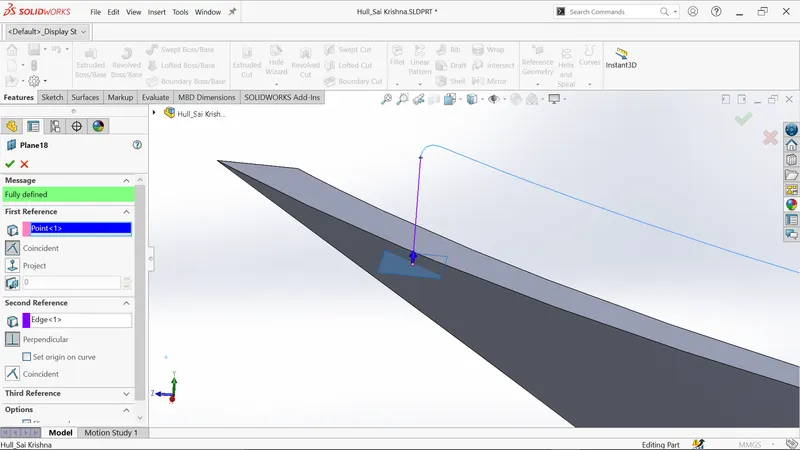
- Create the new plane as showw below.
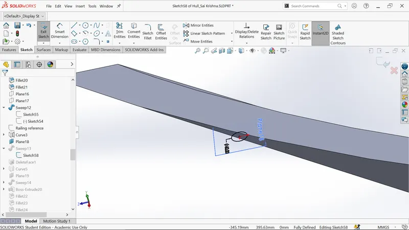
- Sketch on new plane and draw circle of 60 mm.
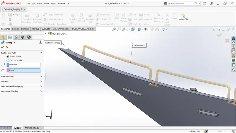
- Perform the sweep for railing.
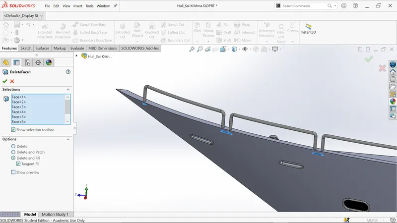
- Use delete face feature for deleting the extra faces on outside.
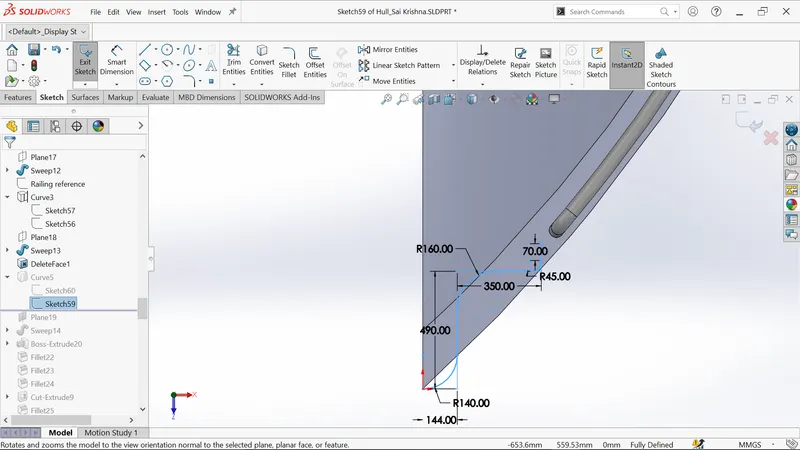
- Sketch on top plane as shown below.
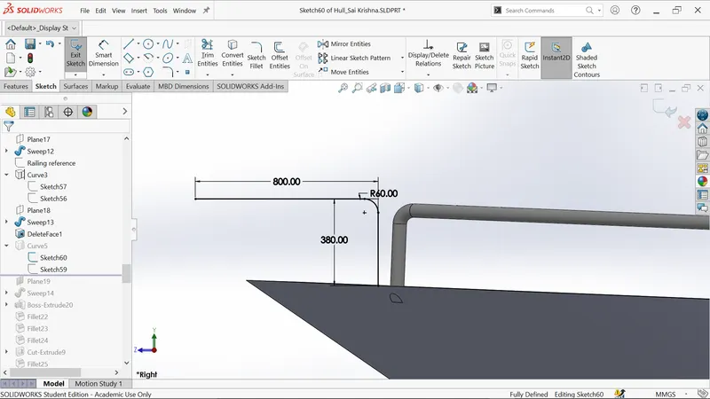
- Sketch on mid plane as shown below.
- Project the last two sketches using project curve feature.
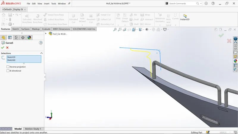
- Create the new plane as shown below.
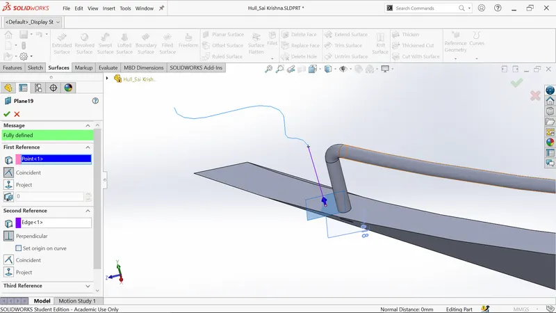
- Sketch on new plane and draw circle of 60 mm.
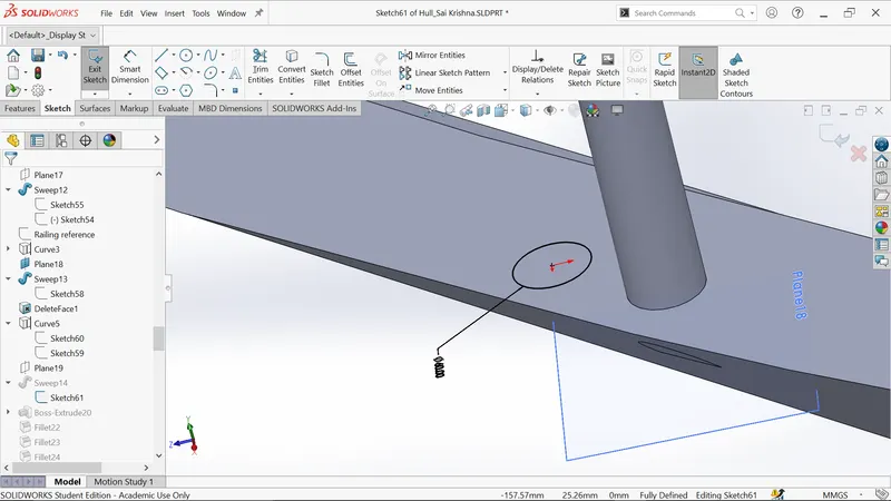
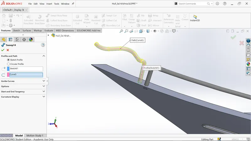
- Perform the sweep for front railing as shown below.
- Sketch on midplane and extrude as shown below.
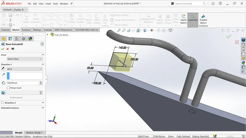
- Appy the fillet for edges.
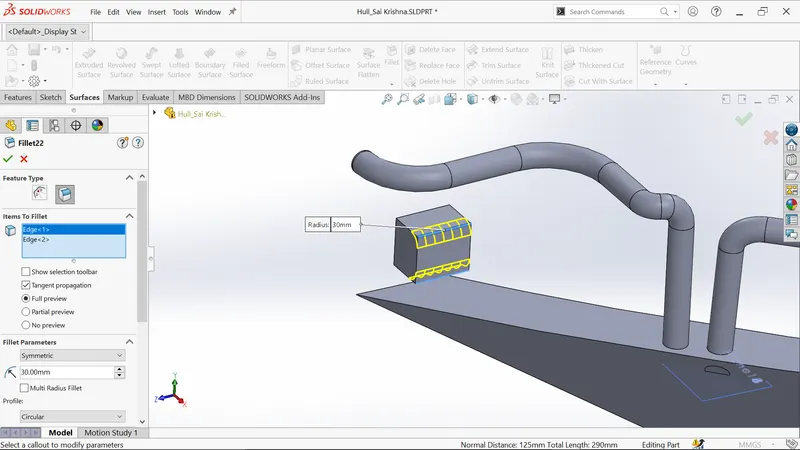
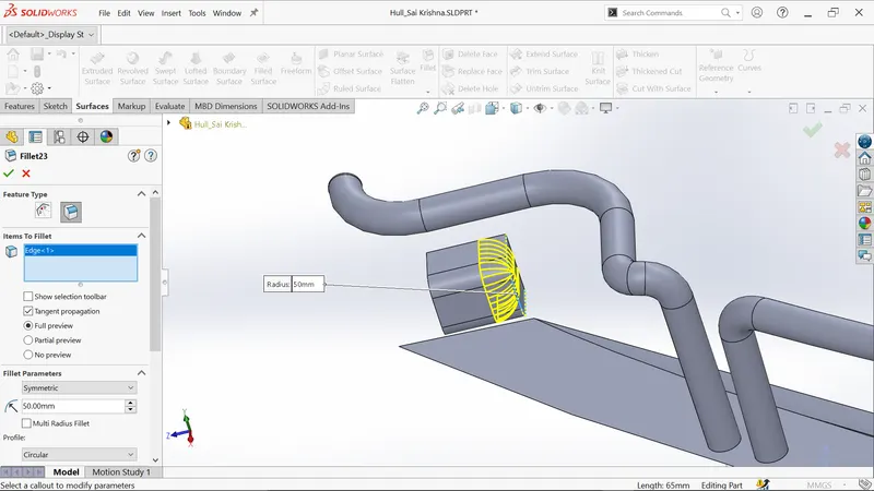
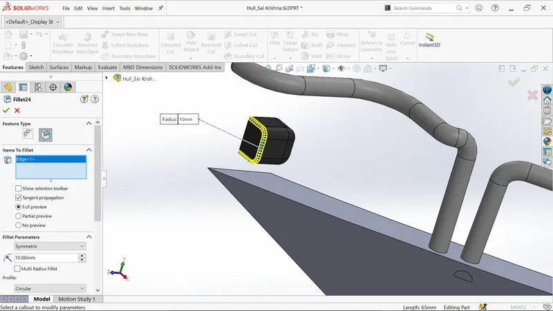
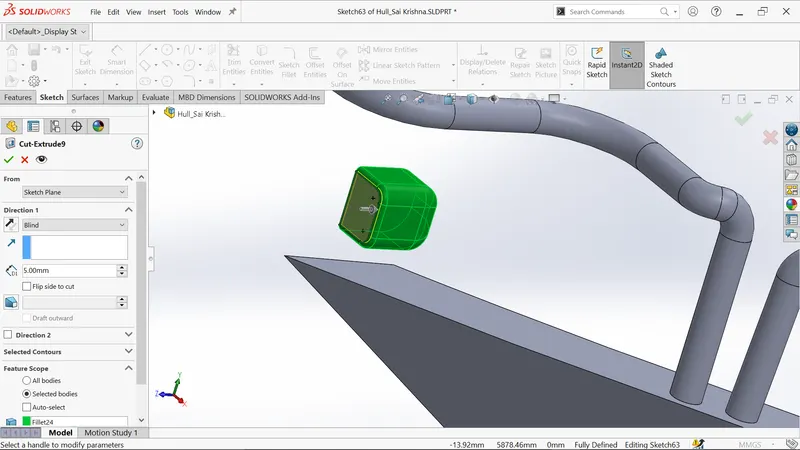
- Select front face of light and covert the edge and cut extrude upto 5 mm.
- Apply the fillet for edges.
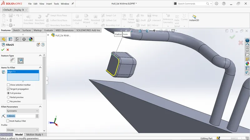
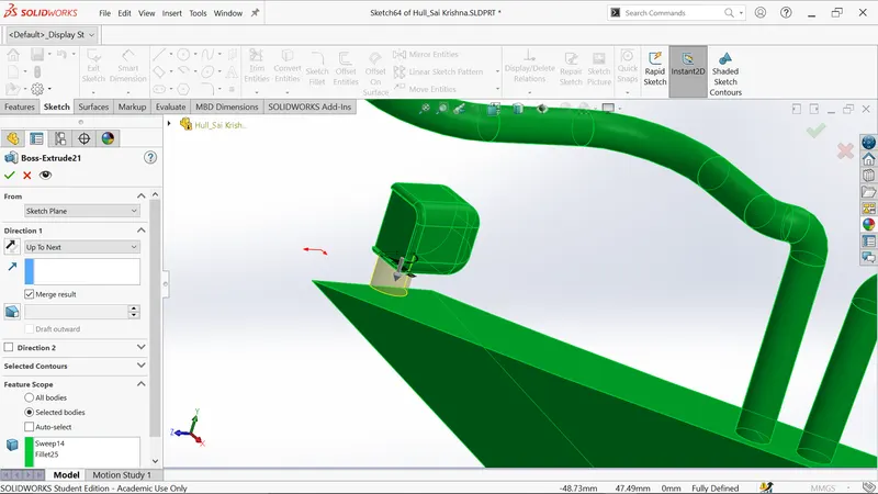
- Sketch on below surface of light with half circle of 70 mm and extrude upto next.
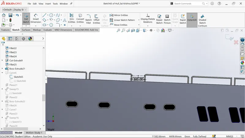
- Create the sketch on midplane as shown in figure.
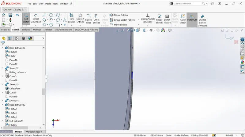
- Create the sketch on top plane as shown in figure.
- Project the last two sketches.
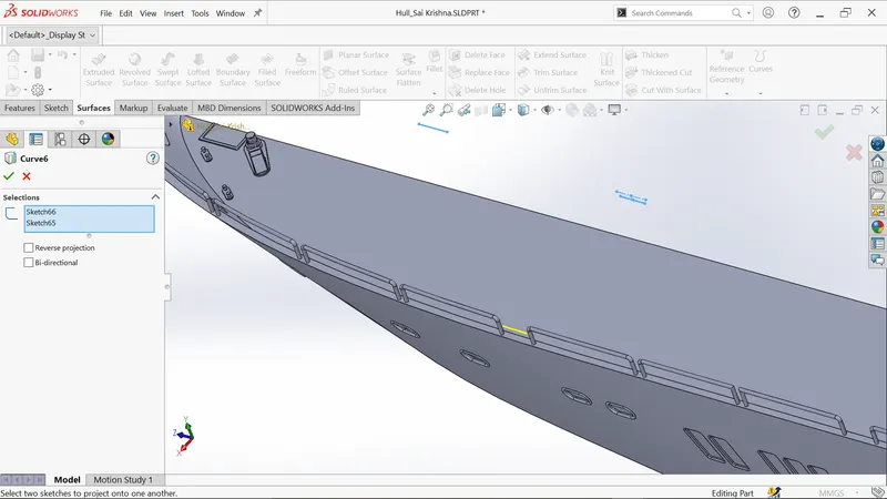
- Create the new plane as shown.
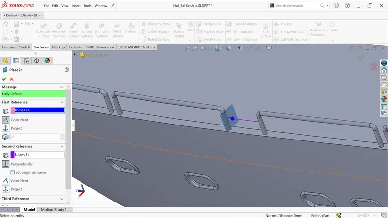
- Sketch on new plane as shown below.
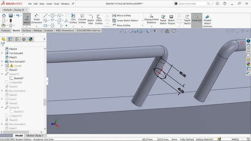
- Perform the solid sweep.
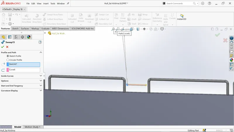
- Draw the line as shown and exit from sketch.
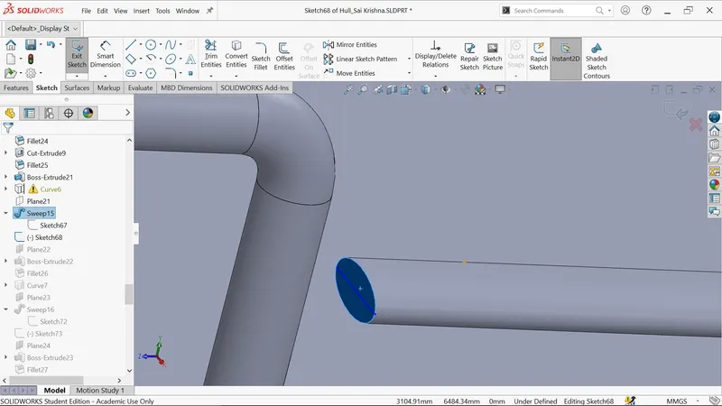
- Create the new plane as shown.
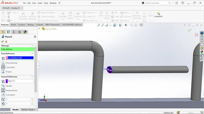
- Sketch on the new plane of two circles and extrude upto surface.
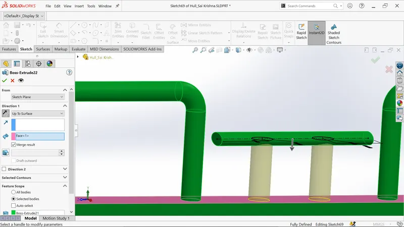
- Apply the fillet for two edges.
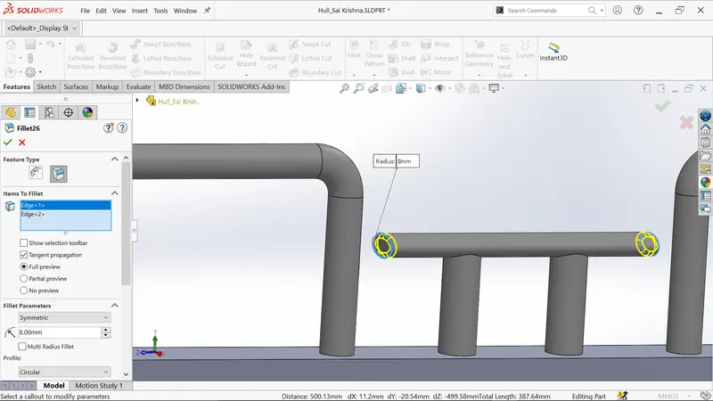
- Repeat the same process for another cable bracket.
- Select the back surface and sketch as per dimensions and extrude as shown.
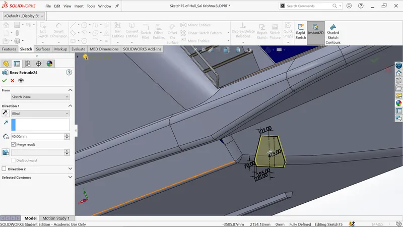
- Select the extrude surface and sketch as per dimensions and extrude as shown.
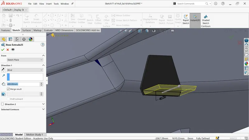
- Apply chamfer for edges.
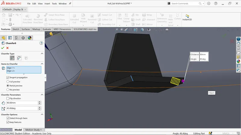
- Apply the fillet for all edges.
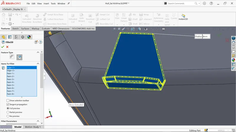
- Select the extrude surface and sketch as per dimensions and extrude as shown.
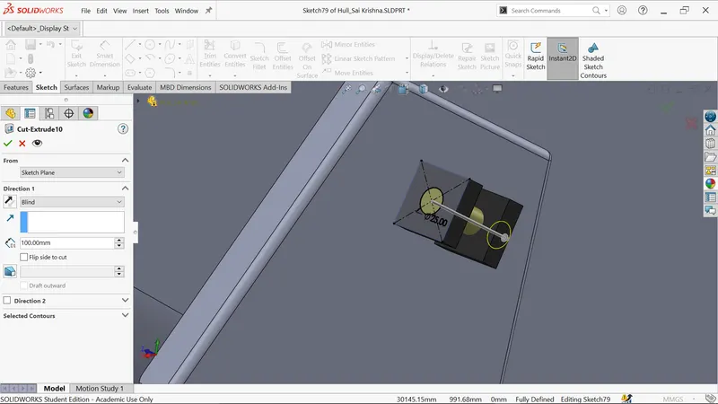
- Sketch on the surface as shown and extrude cut upto 100 mm.
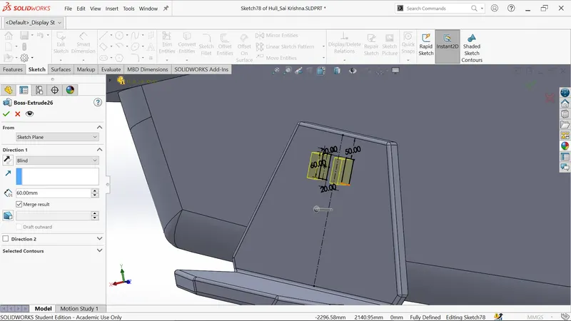
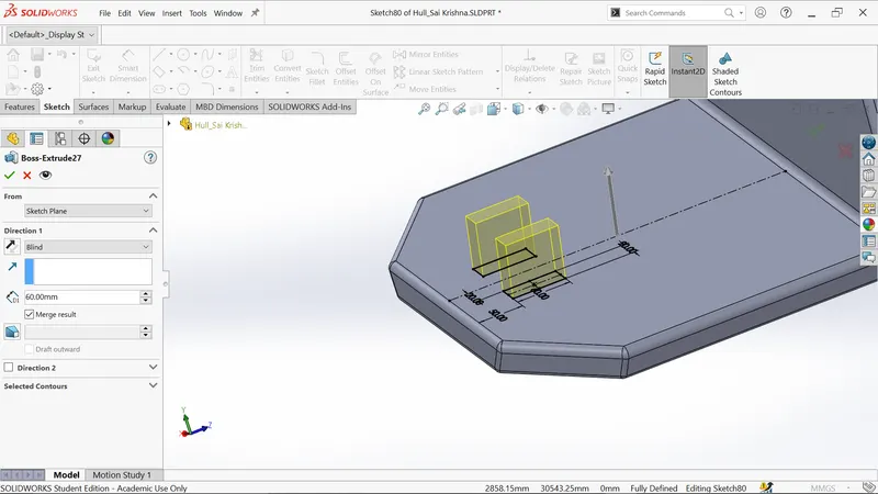
- Sketch on the surface as shown and extrude upto 60 mm.
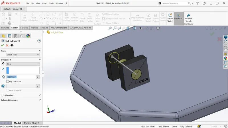
- Sketch on the surface as shown and extrude cut upto 100 mm.
- Apply fillets for edges.
- Create the new plane as shown below.
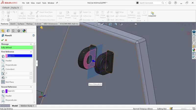
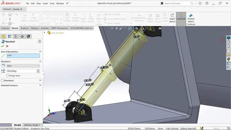
- Sketch on new plane as per dimensions and revolve by selecting blue line as axis.
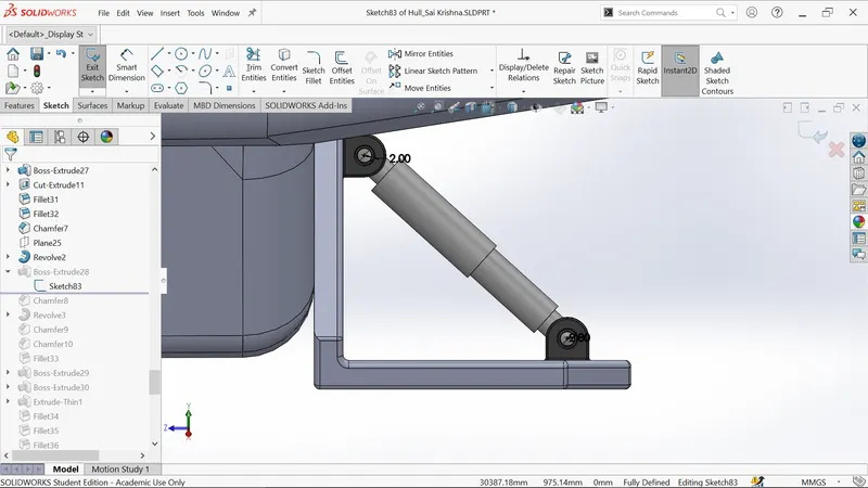
- Sketch on previous plane with two circles of distance 2mm from inner edge.
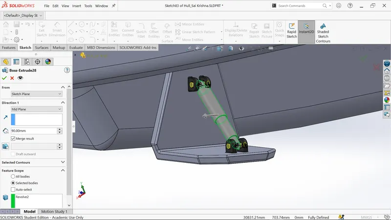
- Extrude th circles of 90 mm.
- Create the sketch on midplane and add the dimensions as shown.
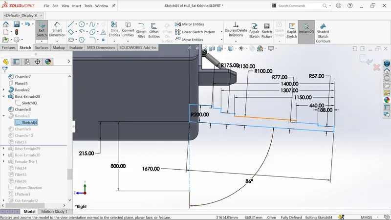
- Perform revolve by selecting blue line as axis.
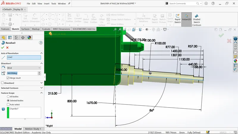
- Apply the necessary fillets.
- Sketch on midplane and add dimensions as shown and extrude.
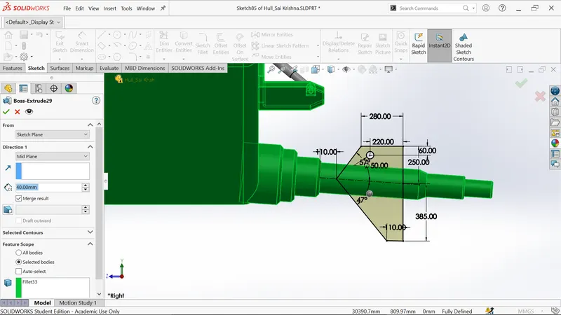
- Sketch on midplane and add dimensions as shown and extrude.
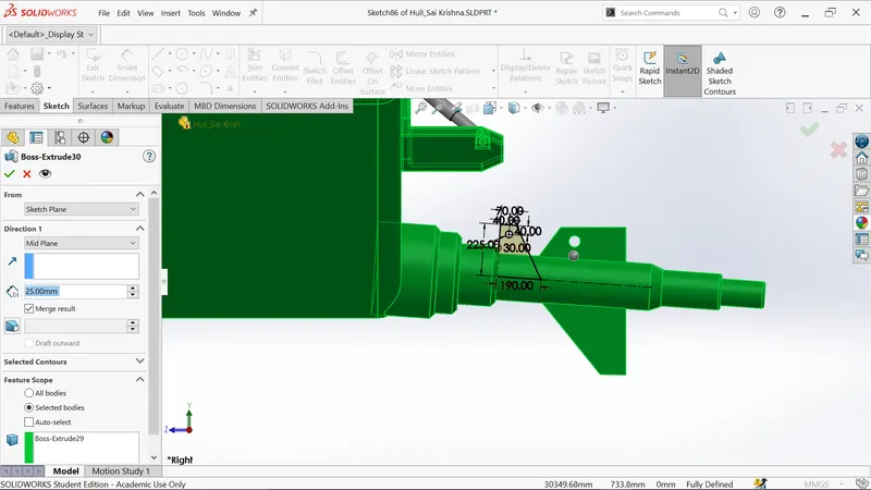
- Sketch on midplane by taking line and perform the thin extrude.
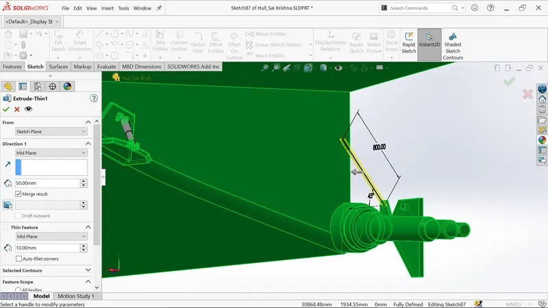
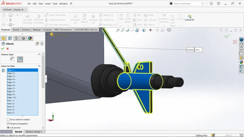
- Apply the fillets as shown.
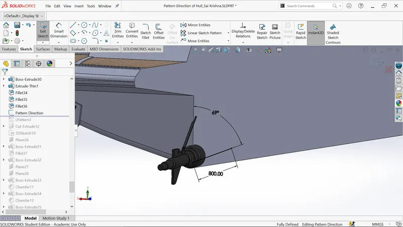
- Select the back surface and sketch as shown and change this sketch name as pattern direcction.
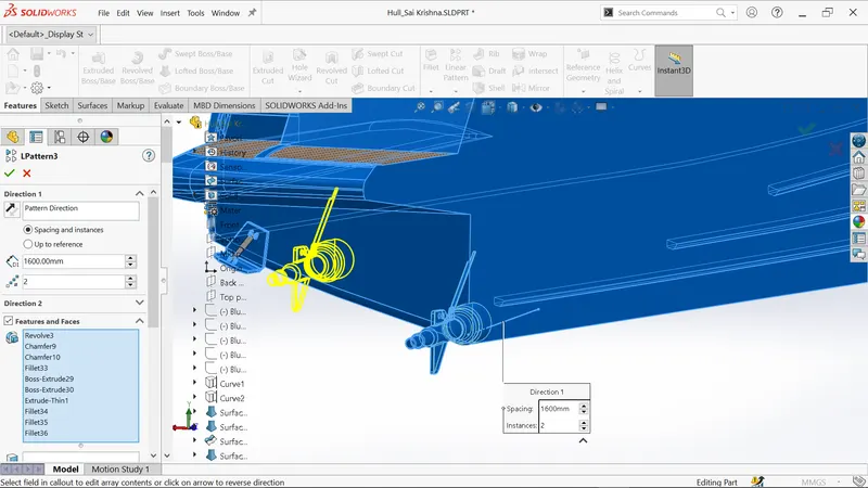
- Apply the linear pattern as shown.
- Sketch on front plane as per dimensions.
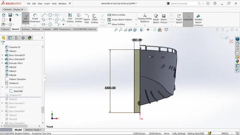
- Perform cut extrude as through all.
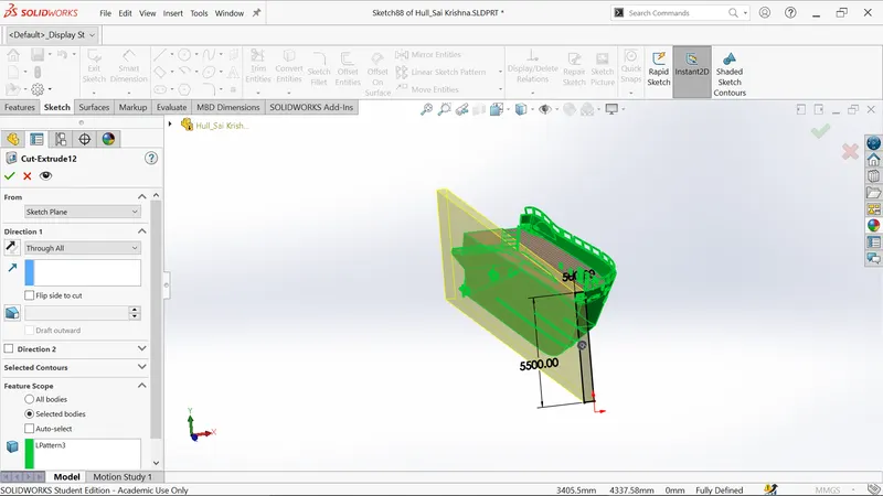
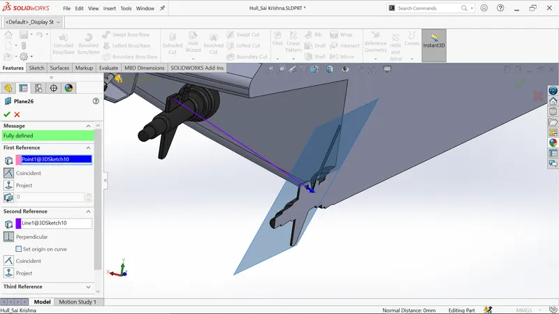
- Create the 3D sketch and draw line and after that create new plane as shown.
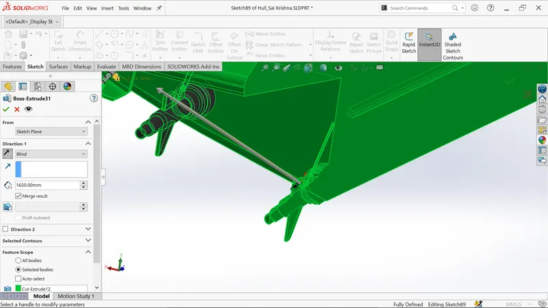
- Perform boss extrude with depth 1650 mm.
Sketch on midplane as shown below and extrude.
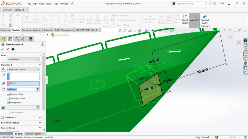
- Create new plane as shown.
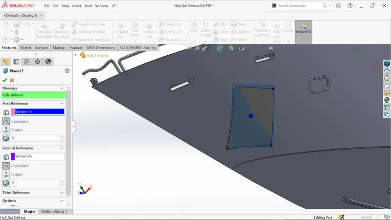
- Create another new plane taking reference as before palne as shown.
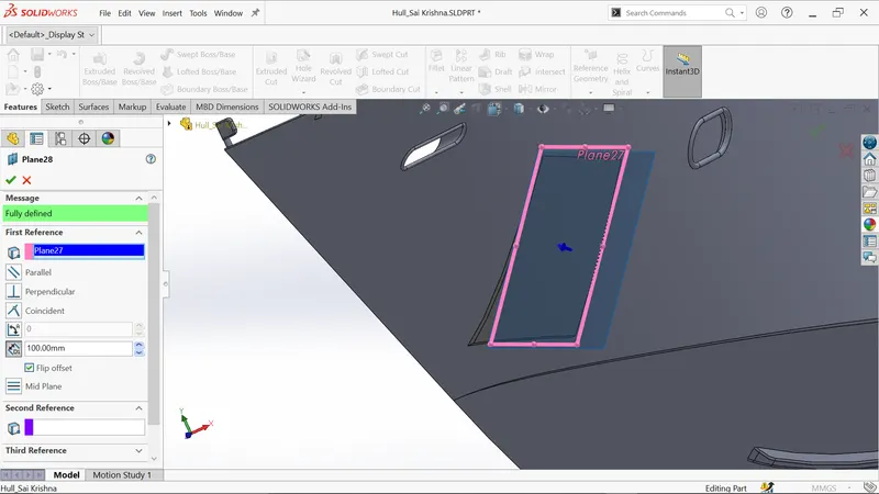
- Sketch on new plane and extrude as shown.
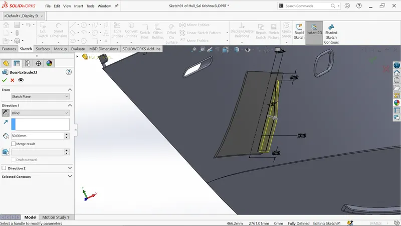
- Apply distance distance chamfer feature.
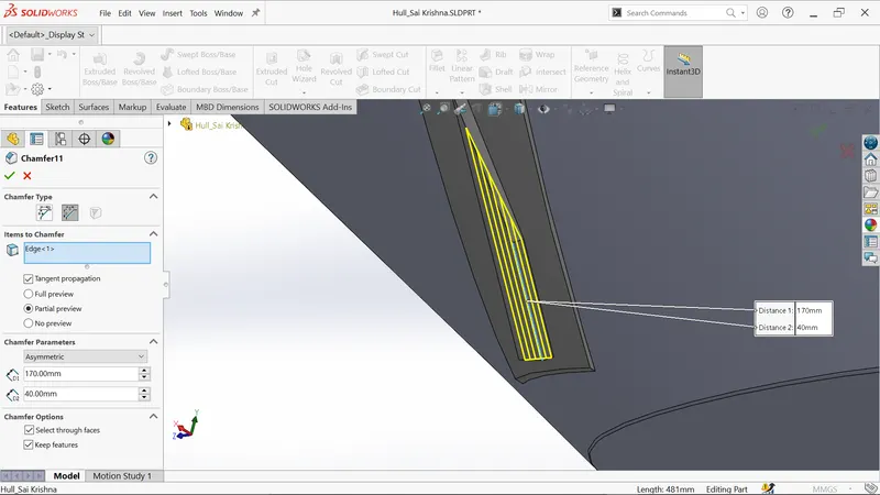
- Again sketch on new plane and extrude as shown.
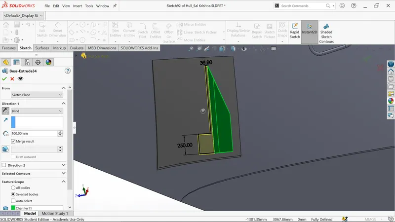
- Apply distance distance chamfer feature.
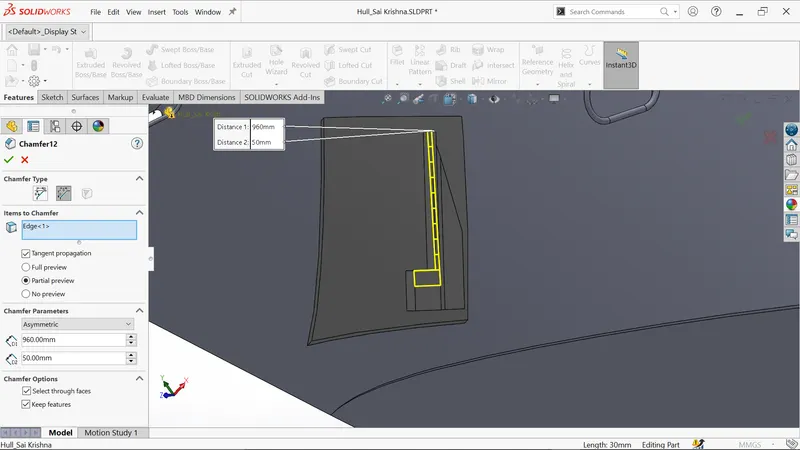
- Again sketch on new plane and extrude as shown.
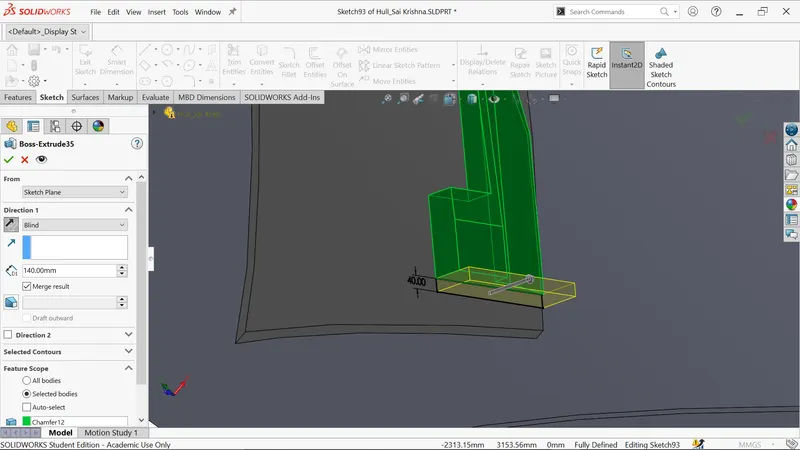
- Select left surface of anchor and sketch and extrude as shown.
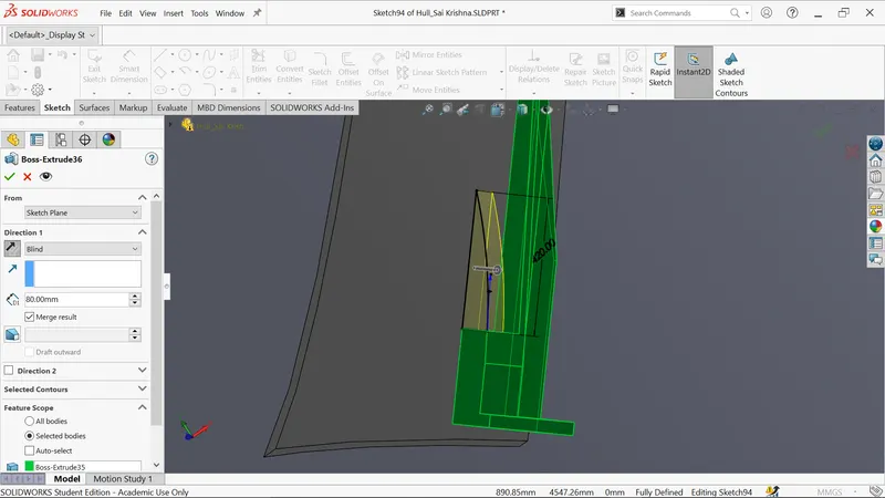
- Apply the necessary fillets.
- Mirror the half anchor for obtaining full anchor.
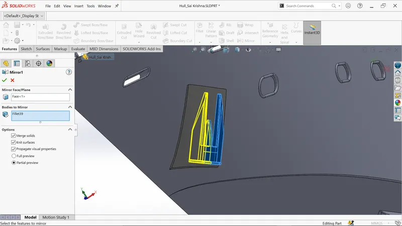
- Again sketch on new plane and extrude from back as shown.
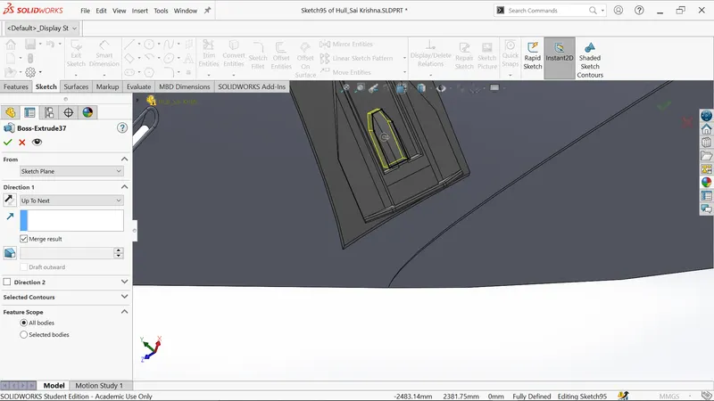
- Sketch on midplane and extrude as shown.
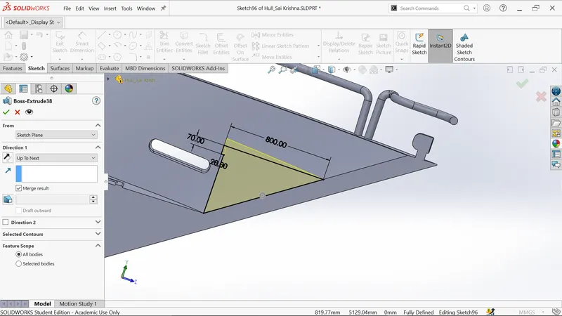
- Sketch on midplane as shown below for garage body and perform thin extrude cut.
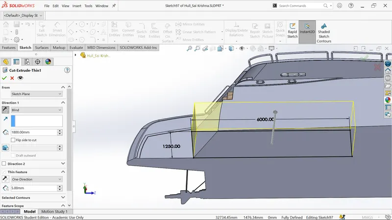
- Select on inner extrude surface and make sketchand cut extrude as shown.
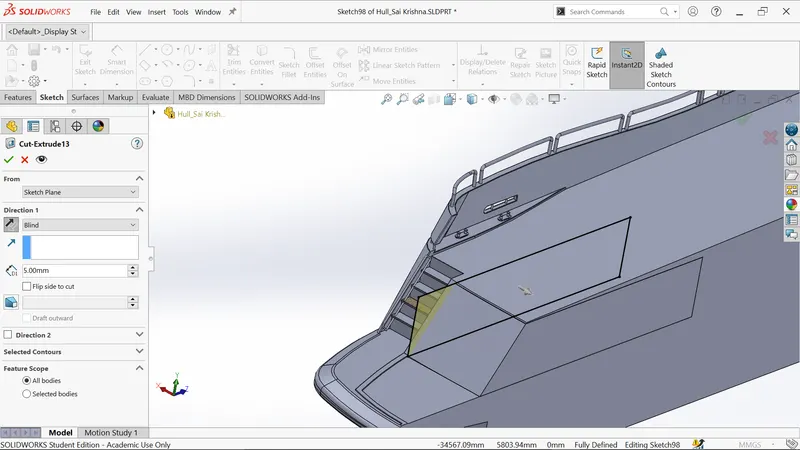
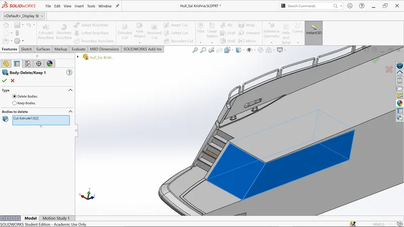
- Use the body-delete/keep to add or remove the garage body from the hull.
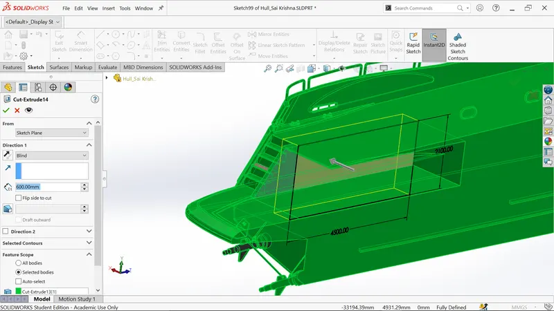
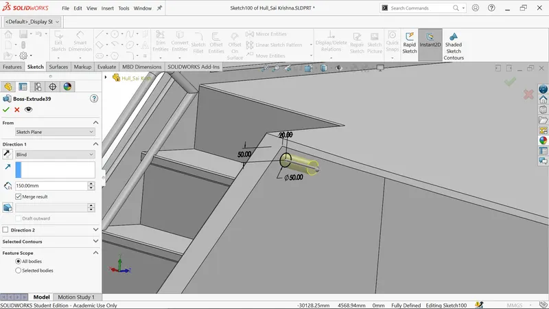
- Sketch on surface with circle of diameter 50 mm and extrude as shown.
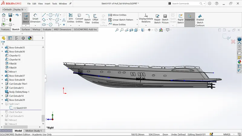
- Sketch on midplane and draw staright line and two splines with offset as shown below.
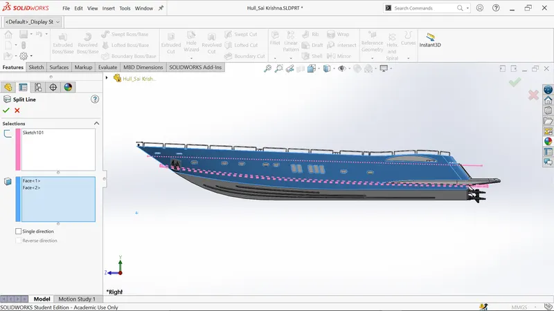
- Use the spline line feature to create split lines at hull.
- Add the necessary appearances.
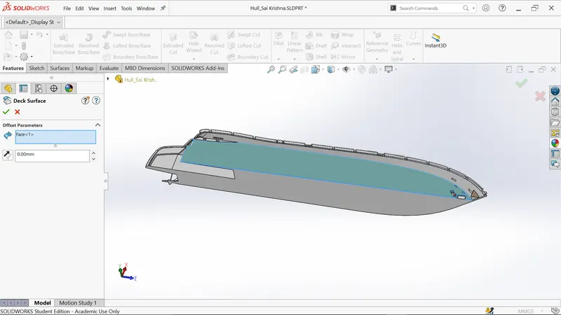
- Using surface offset, copy the deck surface used for creating another parts of yacht.
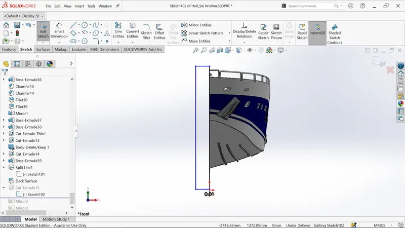
- Sketch on front plane and draw rectangle as shown.
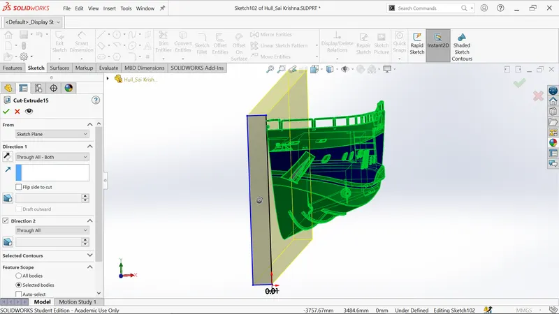
- Extrude the rectangle through all both directions.
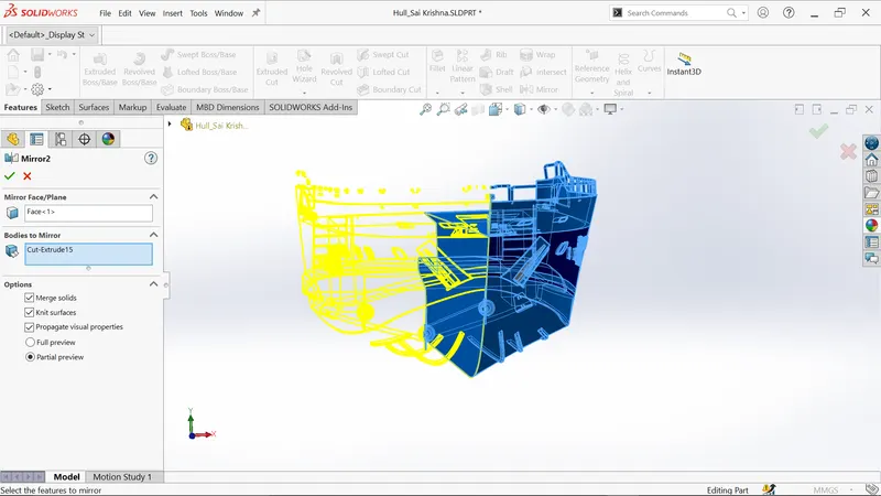
- Mirror the hull for obtaining the full hull body.
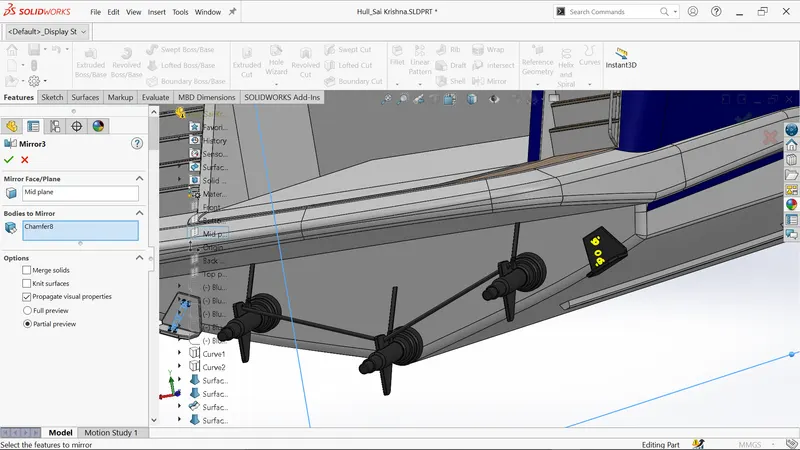
- Use mirror feature to mirror the stabiliser on another side.
- Add the appropriate decals on the hull, steps and appearances.
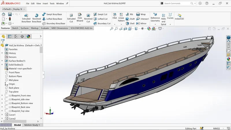
- Finally save the part model as hull.
Views of Hull:
Front view:
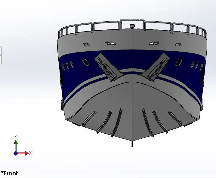
Right view:
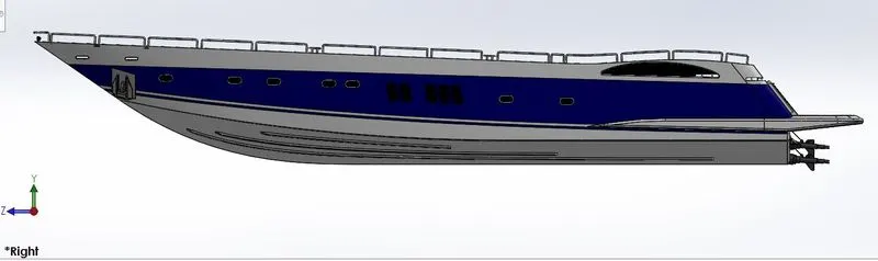
Isometric view:
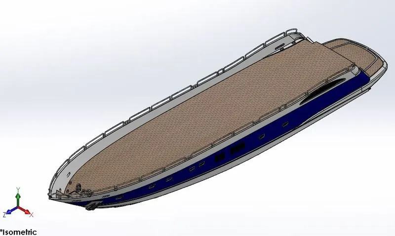
Render image of Hull:
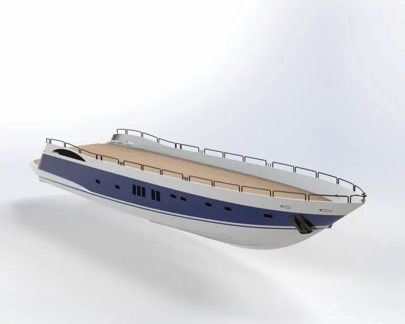
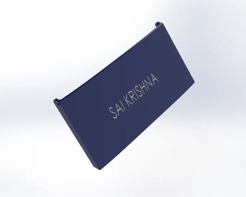
Modelling of Garage Door
The garage door is a large door on a garage that opens either manually or by an an electric motor which is used to protect the things inside garage.
Features used:
Sketch:Sketch creates 2D drawing for the model of having entities like lines,splines,circles etc.
Cut Extrude:Used to remove the material fro extrude body.
Shell:This feature is used for defining the thickness of thick and thin materials.
Fillet:Used for creating smooth edges in order to avoid to avoid sharp edges.
Mirror:Used to mirror the selected features or bodies.
Procedure to be followed:
- Firstly open the exported garage body which is seperated from the hull.
- Select right plane, click sketch and draw four lines as shown.
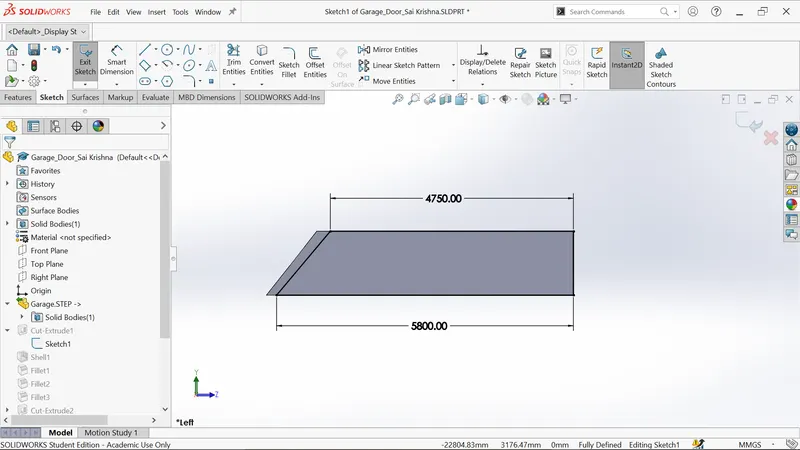
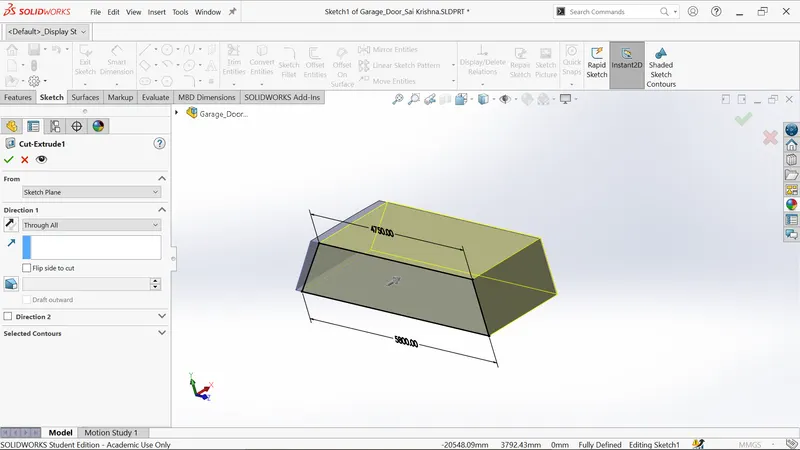
- Create extrude cut from through all direction as shown.
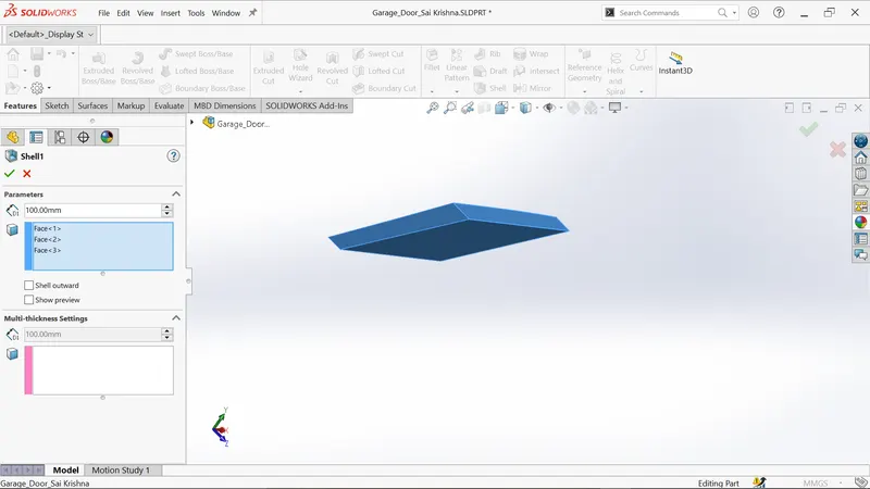
- Create the shell by selecting all the three blue surfaces.
- Apply the fillet for edge as shown.
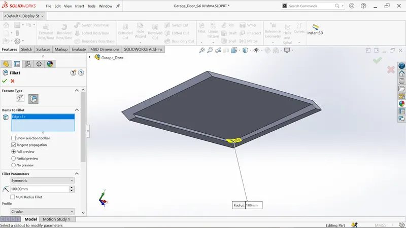
- Apply the fillet on the blue edge as shown.
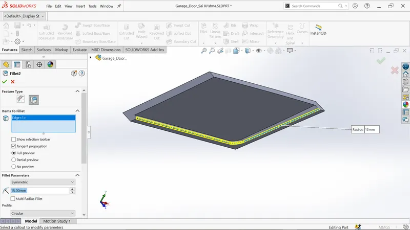
- Apply the fillet on the blue edge as shown.
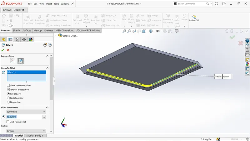
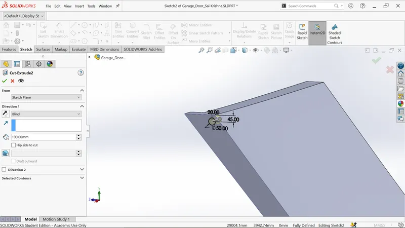
- Select right side surface and sketch circle with dimensions as shown.
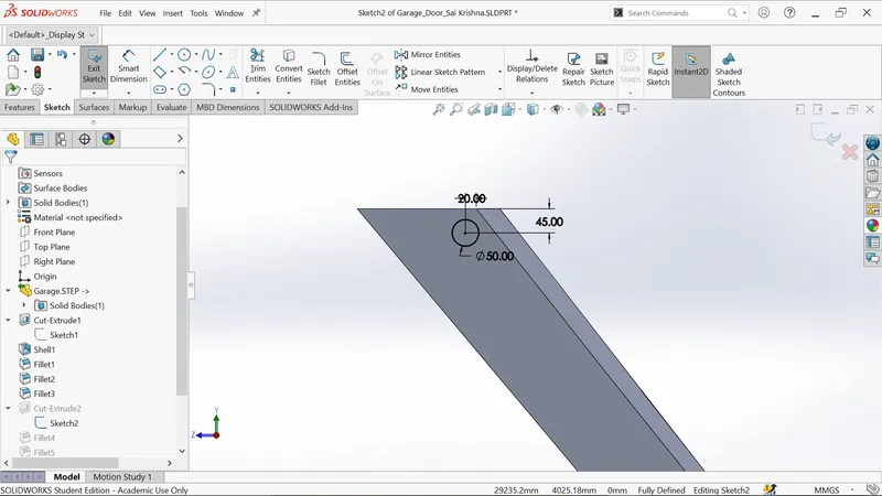
- Extrude circle upto 100 mm.
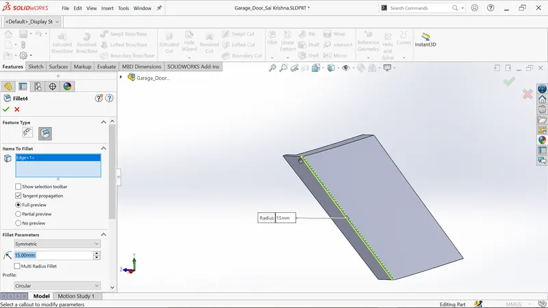
- Apply the fillet on the blue edge as shown.
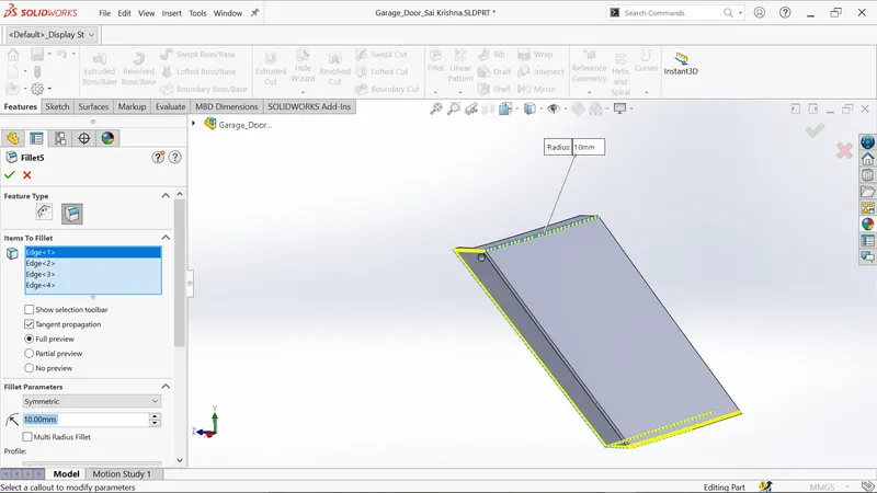
- Apply the fillet on the blue edges as shown.
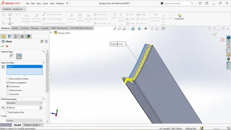
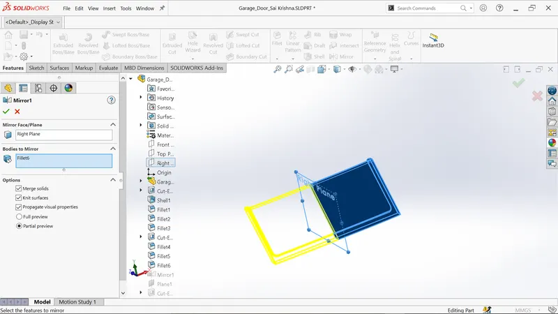
- Mirror the garage body for obtaining full garage body.
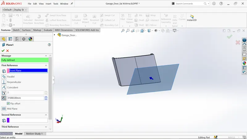
- Create new plane with reference from front plane of offset with 31000mm.
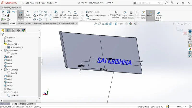
- Create new sketch on new plane and add the text as shown.
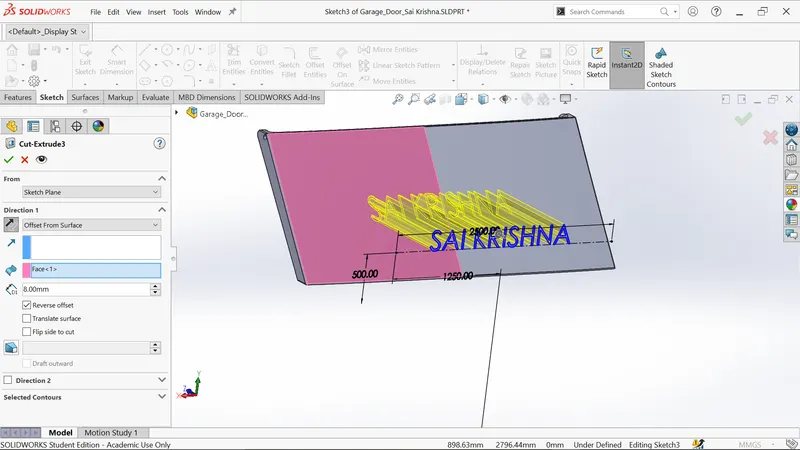
- Perform cut extrude feature in which the text is incorporated within the garage body.
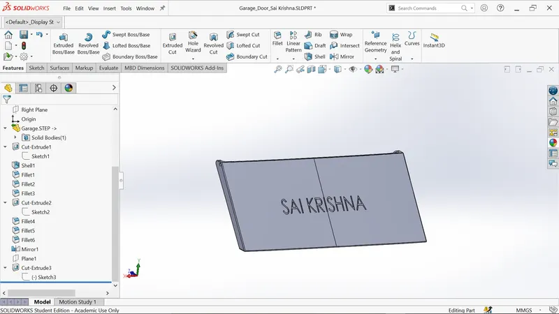
- Apply the appearances for text as well as garage body.
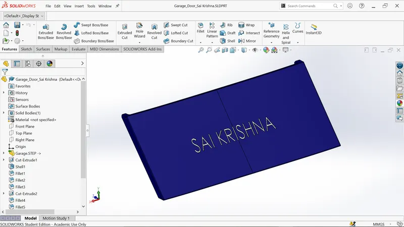
- Finally save the part model as Garage Door.
Views of Garage Door:
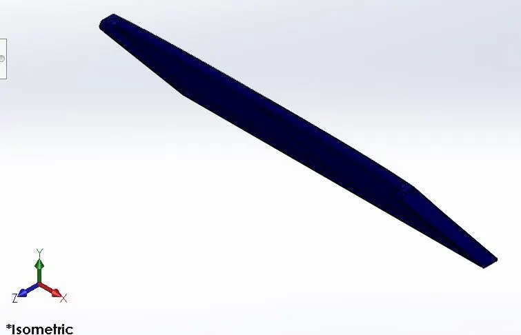
Front view:
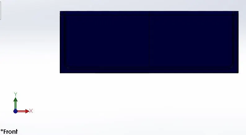
Back view:
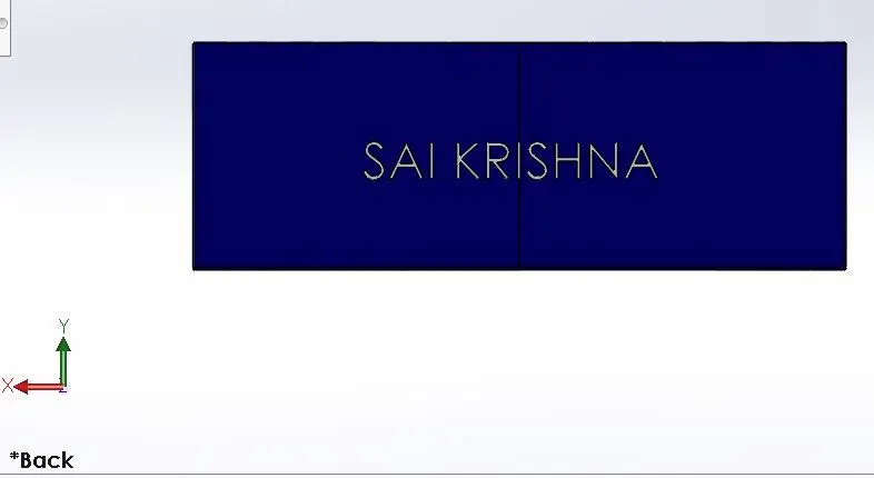
Isometric view:
Render image of Garage Door:
Modelling of Front Seat
Front seat is used for resting the passengers on it and it is placed on the front side of yacht.
Features used:
Sketch:Sketch creates 2D drawing for the model of having entities like lines,splines,circles etc.
Sweep surface:Sweeps a closed profile along a open or closed path to create surface feature.
Surface Extrude:Extrude a sketch contours in one or two directions to create surface feature.
Trim Surface:Used to trim the selected surfaces by trim tool.
Filled Surface:Used to fill the surface material in between two surfaces.
Lofted Surface:Used to fill the gap between two curved surfaces.
Knit Surface:Used to combine multiple surfaces into single surface.
Chamfer:Used for creating sloping surfaces at the edges.
Revolve:Used to create revolve body by selecting centerline as axis.
Cut Extrude:Use to remove material extrude body.
Mirror:Used to mirror the selected features or bodies.
Dome:Used to create concave shape on surface.
Fillet:Used for creting smooth edges in order to avoid sharp edges.
Procedure to be followed:
- Initially open the blueprint set up file and save the file as Front seat.
- Next import the deck surface from the hull by selecting only the surface body.
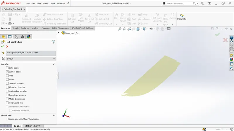
- Select deck surface and create new sketch,switch to top view and draw the spline as shown below.
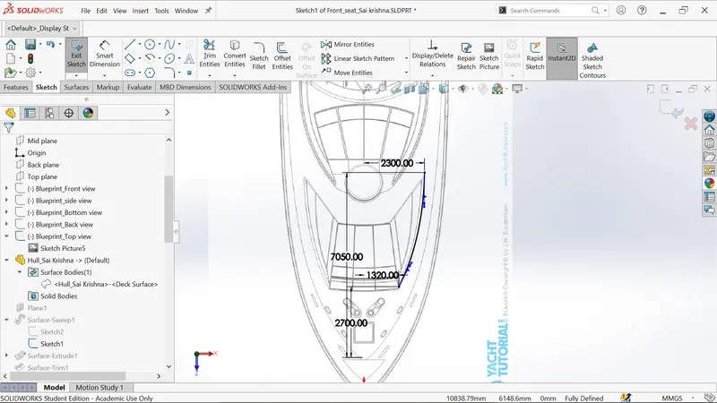
- Create a new plane as shown.
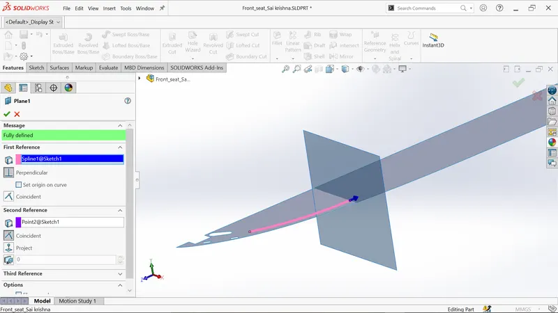
- Create new sketch on new plane and draw the spline as shown.
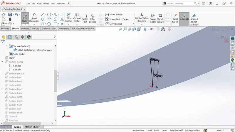
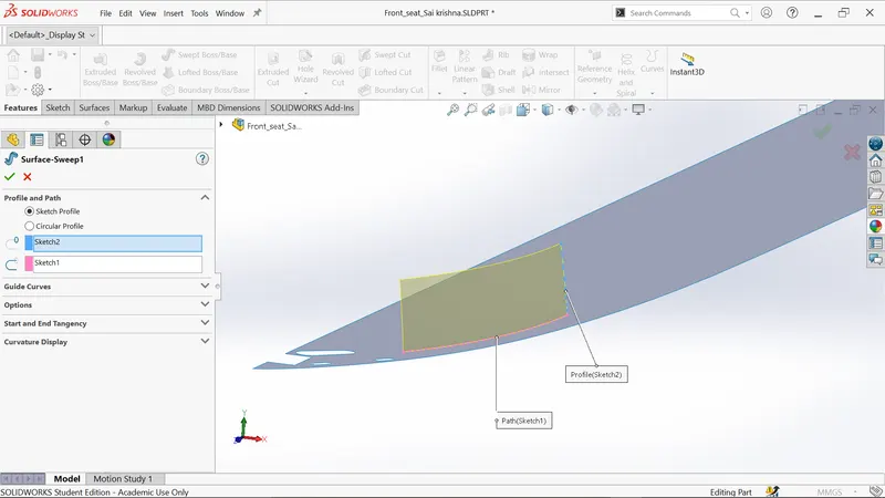
- Create a surface sweep using two sketches with surface sweep feature as shown.
- Select 2D sketch on deck surface and draw lines and can view from top view.
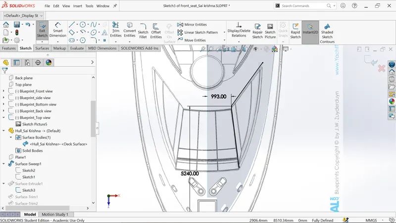
- Create surface extrude for above sketch.
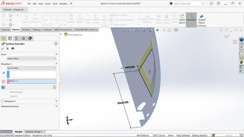
- Trim the surface of purple area using trim surface feature.
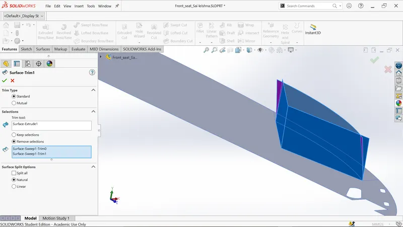
- Trim the surface of purple area using trim surface feature.
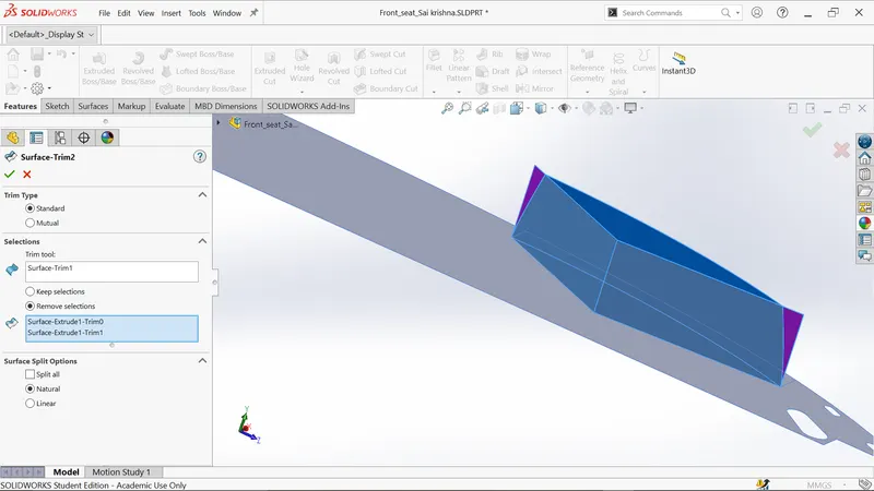
- Create surface fill by selecting three edges as shown.
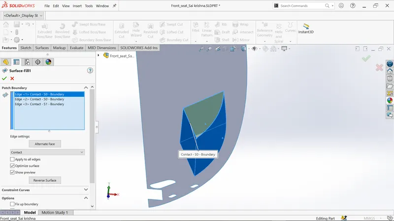
- Select the top surface of filled surface and create a new sketch,draw the spline as shown below.
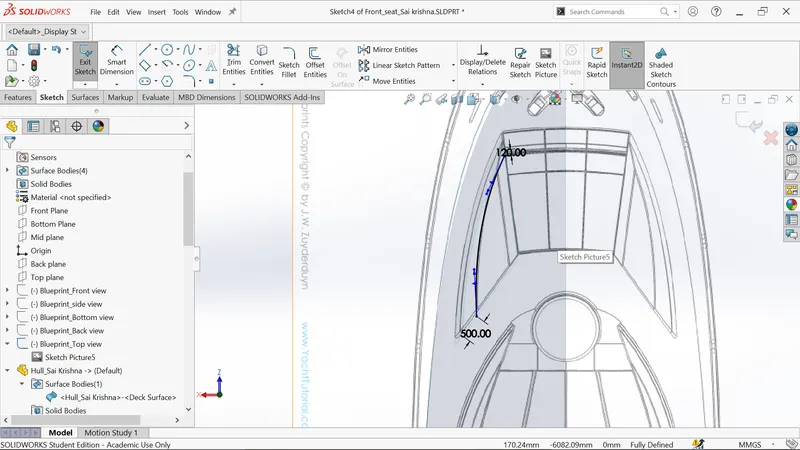
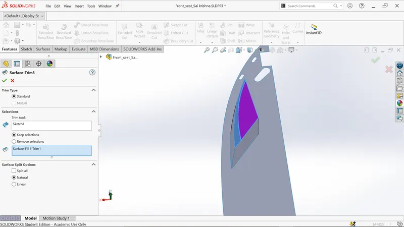
- Trim the blue surface by selecting sketch 4 as trim tool.
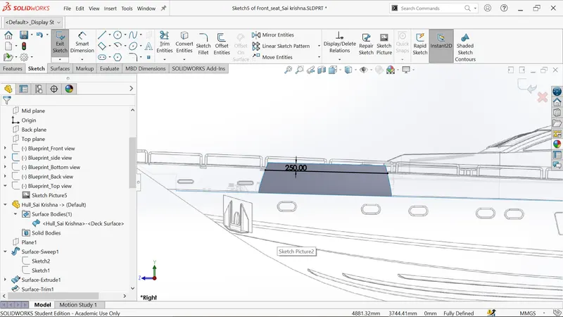
- Sketch on midplane and draw the line as shown.
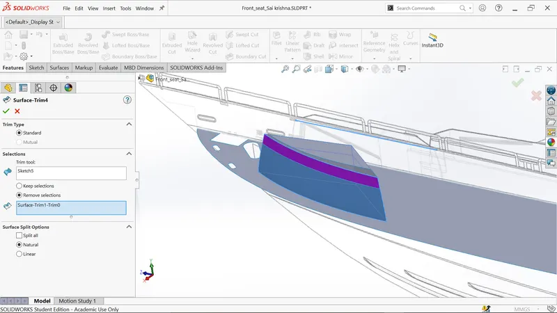
- Trim the purple surface by selecting sketch5 as trim tool.
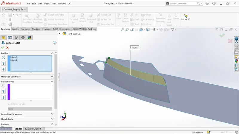
- Create the surface loft by selecting edge1 and edge2.
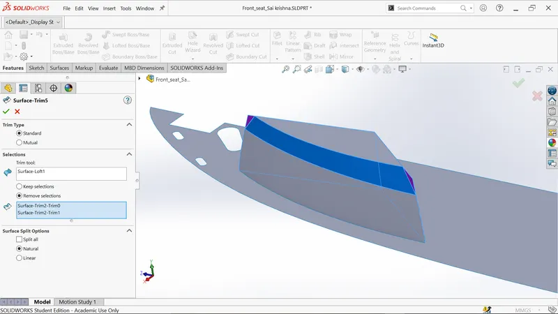
- Trim the purple surface by selecting surface loft1 as trim tool.
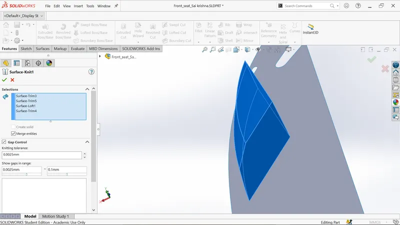
- Knit all the blue sufaces as shown below.
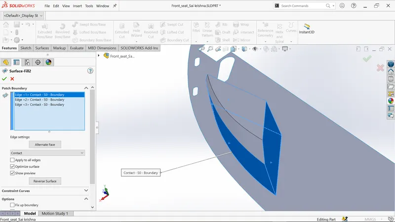
- Create another surface fill by selecting three boundary edges as shown.
- Again knit all surfaces in which all the surfaces became together.
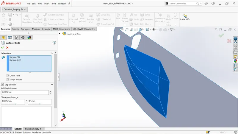
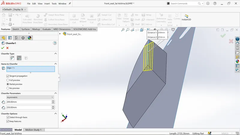
- Apply the distance distance chamfer.
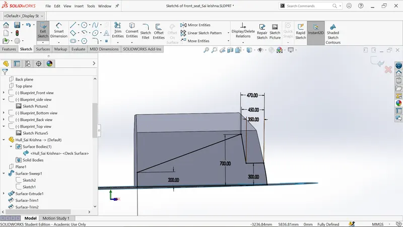
- Create new sketch on surface and draw the lines as shown below.
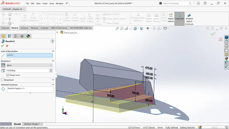
- Create revolve by selecting reference line as axis with angle 10 degree.
- Sketch on top plane and draw the corner rectangle.
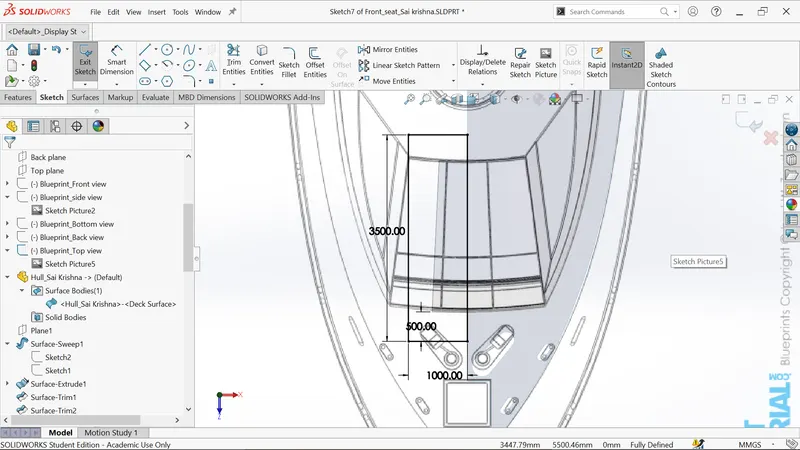
- Extrude cut the rectangle and make sure the direction will be downwards as shown below.
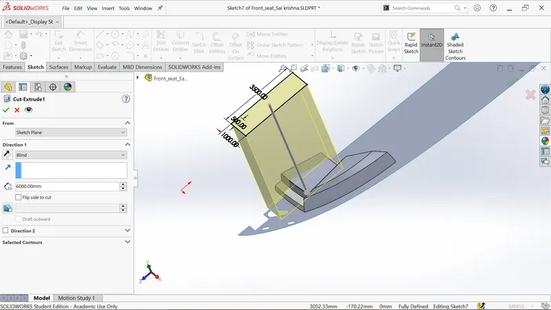
- Create the sketch on the below shown surface and apply the proper dimensions.
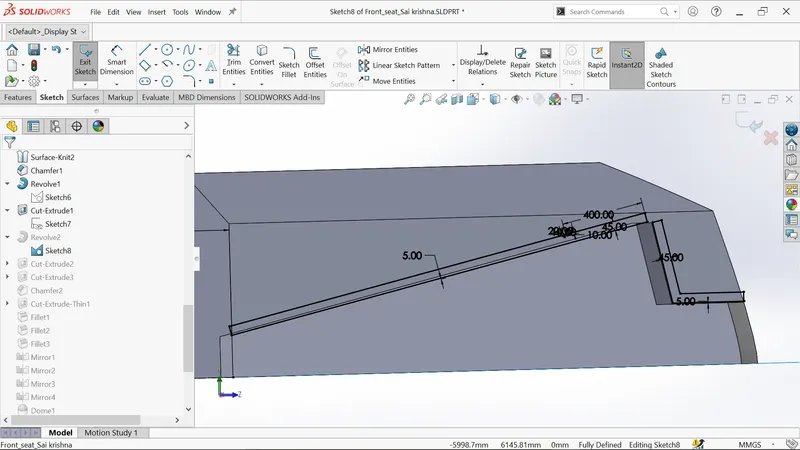
- Create revolve by selecting reference line as axis with angle 10 degree.
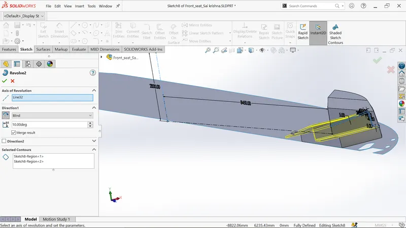
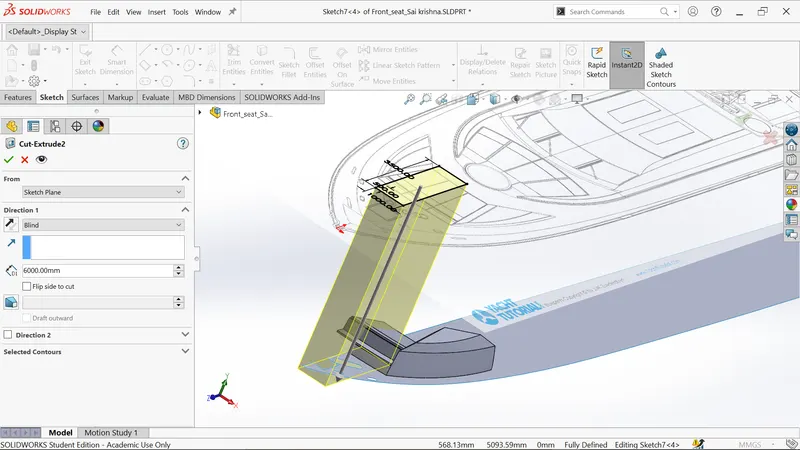
- Again select the sketch7 and show.
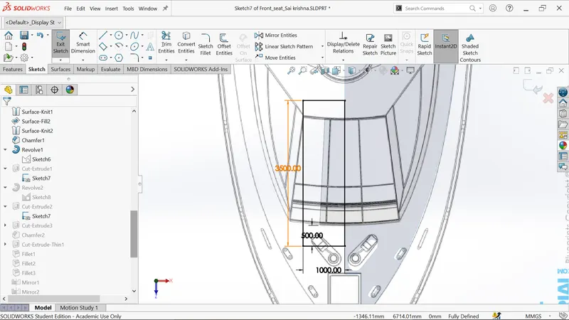
- Perform the cut extrude with 6000mm downwards as shown below.
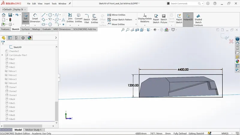
- Create the sketch on the below shown surface and draw corner rectangle with proper dimensions.
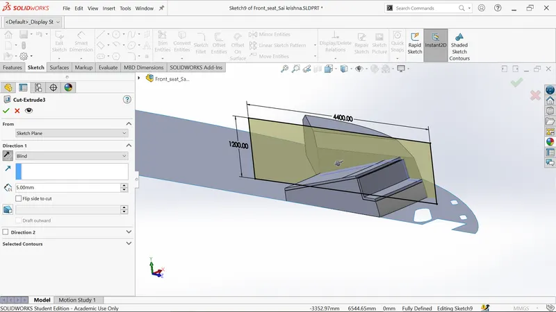
- Perform the extrude cut in outward direction of 5mm.
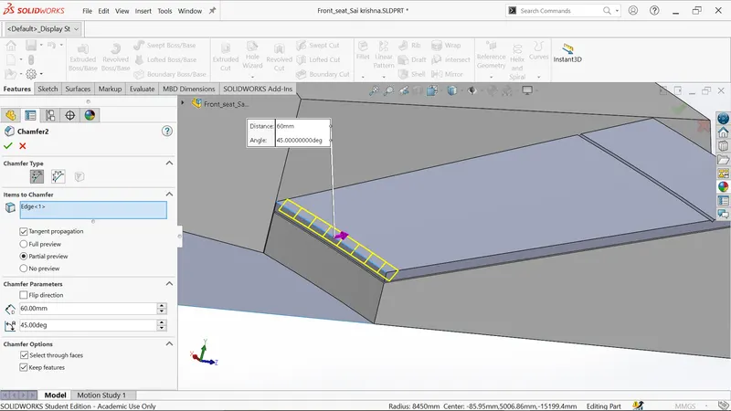
- Apply the angle distance chamfer.
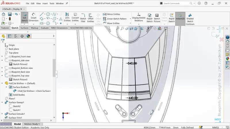
- Sketch on top plane and draw the line connecting with two edges as shown.
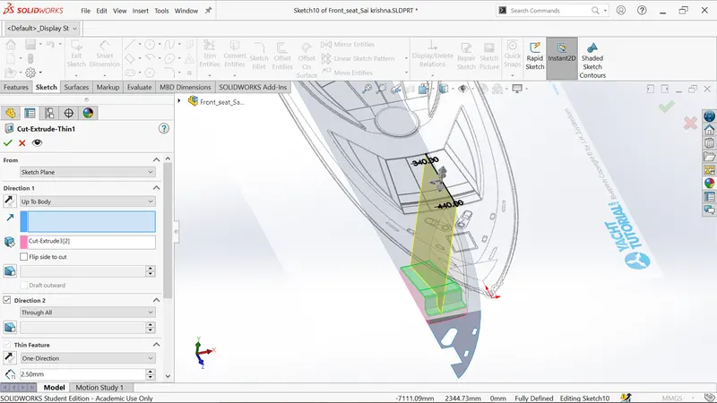
- Perform the extrude cut by enabling the thin feature with thickness 2.5 mm as shown below.
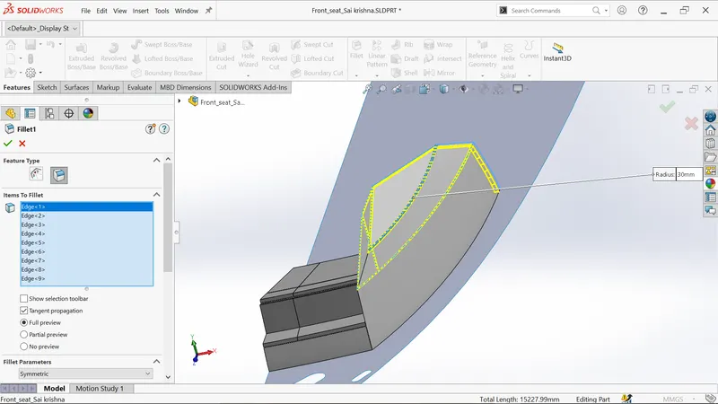
- Apply the fillet for the edges as shown.
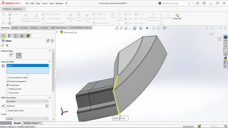
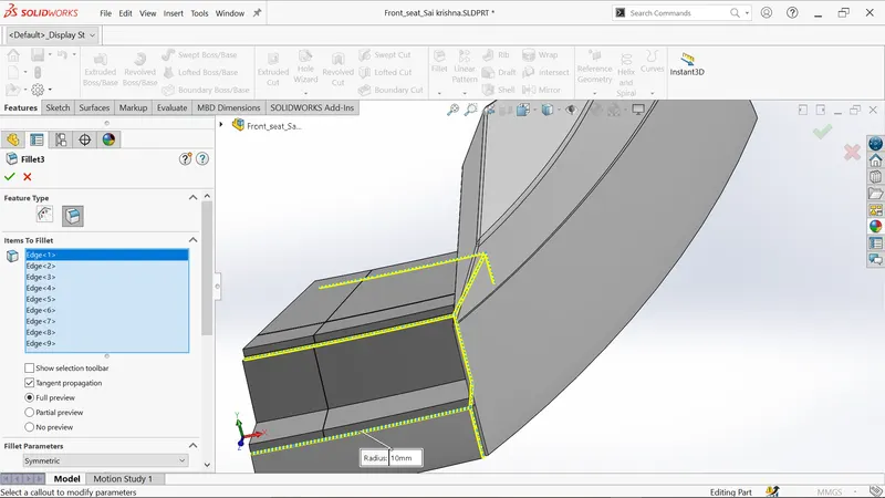
- Mirror the centre body of front seat by selecting blue surface as mirror face.
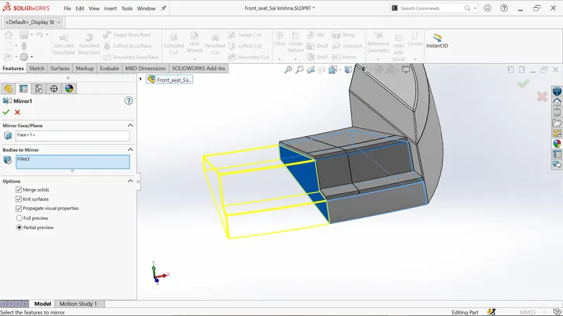
- Mirror the side body of front seat by selecting midplane as mirror face.
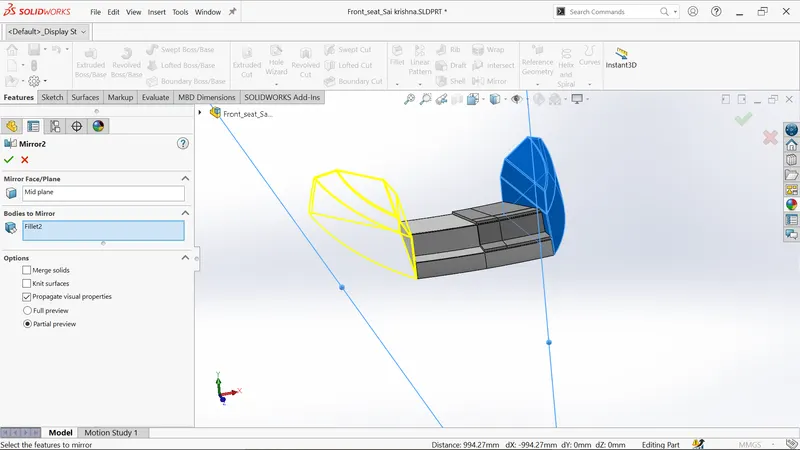
- Mirror the two middle matrasses of front seat by selecting blue surface as mirror face.
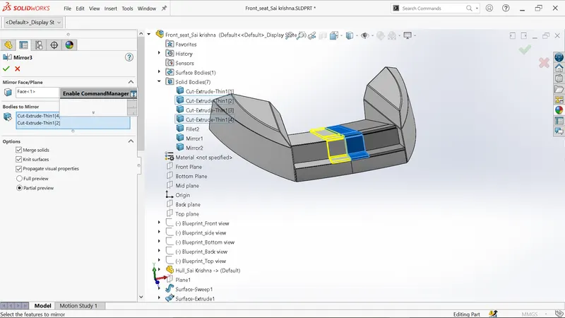
- Mirror the other matrasses of front seat by selecting midplane as mirror face.
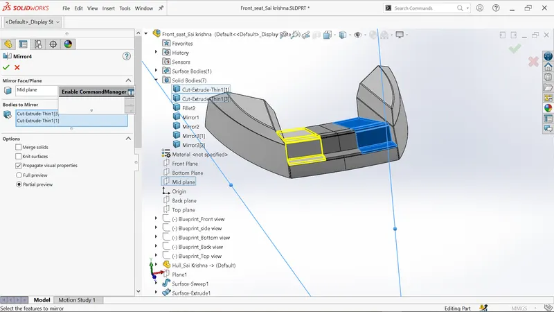
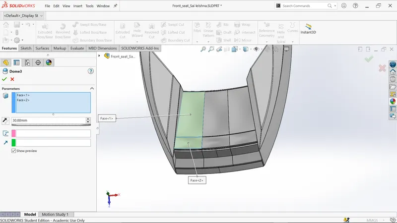
- Apply the dome features on the surfaces as shown on below 3 figures.
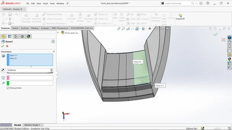
- Apply the dome on two surfaces as shown.
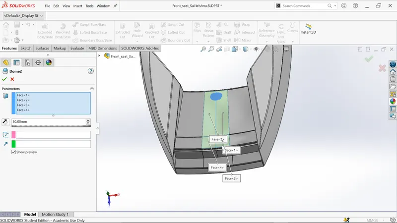
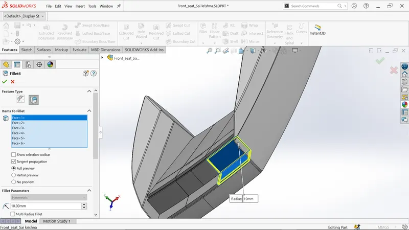
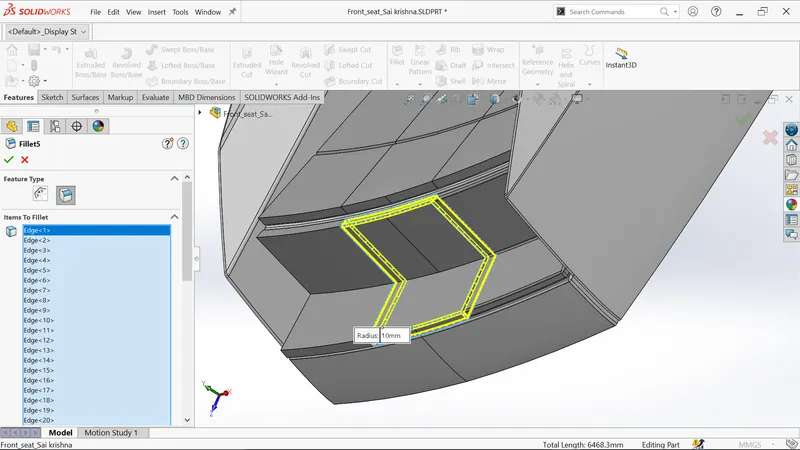
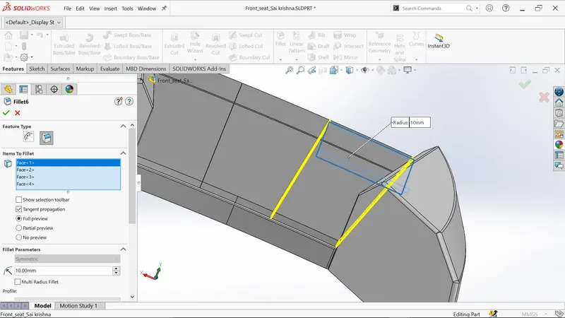
- Apply the fillet of 10 mm for edges as shown.
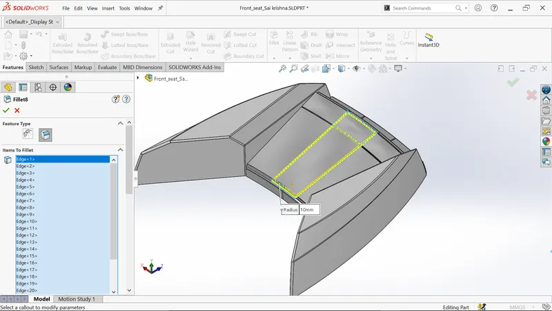
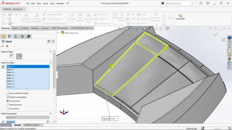
- Add the appearances
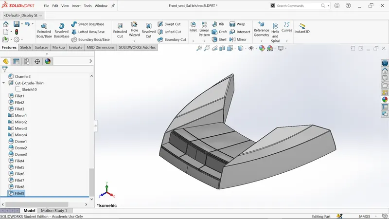
- Finally save the part model as Front seat.
Views of Front Seat:
Front view:
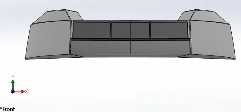
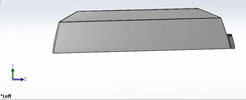
Left view:
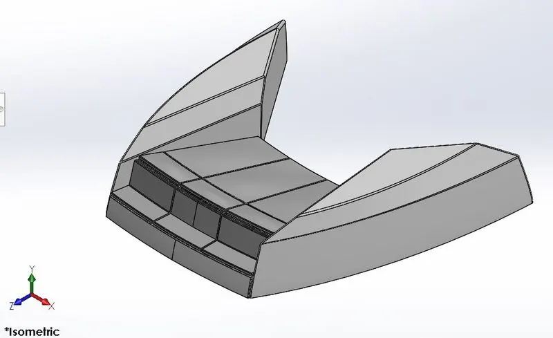
Isometric view:
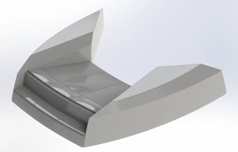
Render image of Front Seat:
Modelling of Middle Seat
Middle seat is used for resting the passengers on it and it is placed on the middle of yacht.
Features used:
Sketch:Sketch creates 2D drawing for the model of having entities like lines,splines,circles etc.
Boss Extrude:Used to extrude 2D sketch into 3D body and it can be done in both forward and reverse directions.
Chamfer:Used for creating sloping surfces at the edges.
Fillet:Used for creating smooth edges in order to remove the sharp edges.
Cut Extrude:Used to remove material from extrude body.
Procedure to be followed:
- Initially open the blueprint set up file and save as the file as Middle seat.
- Next import the deck surface from the hull by selecting only the surface body.
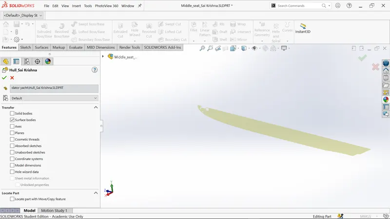
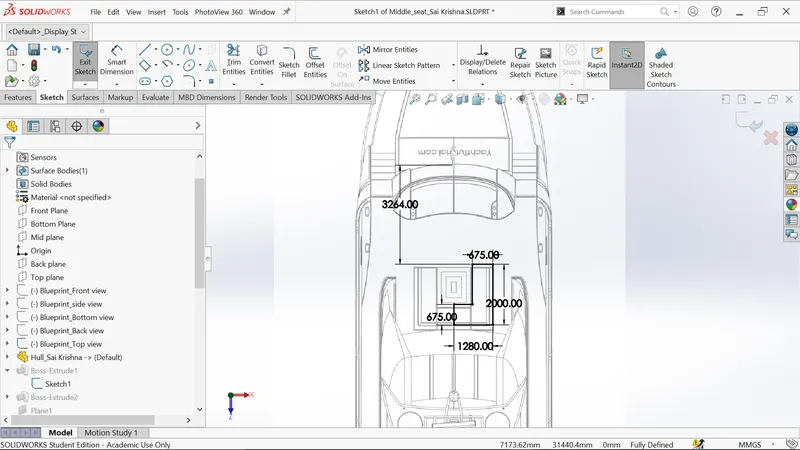
- create sketch on deck surface,draw the line and view from the top as shown below.
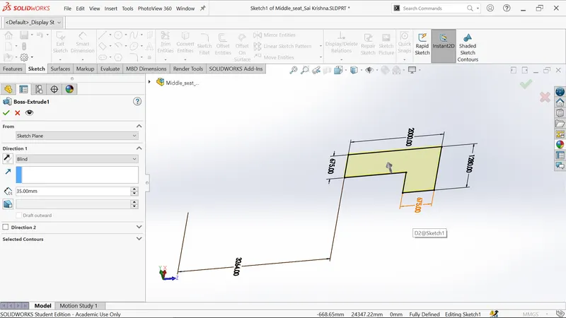
- Create an extrude in upward direction of depth 35mm.
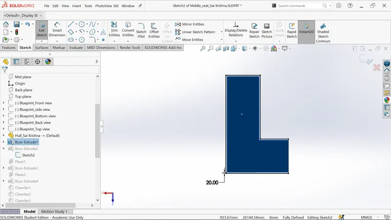
- Sketch on blue surface and offset the surface with 20 mm.
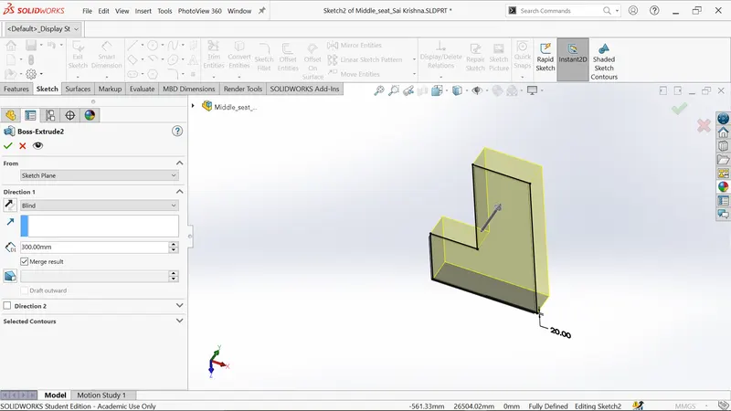
- Create an extrude with depth of 300 mm.
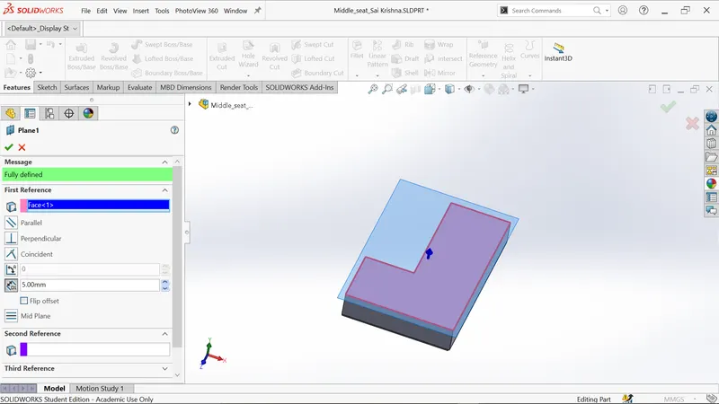
- Create the new plane by selecting pink surface as reference.
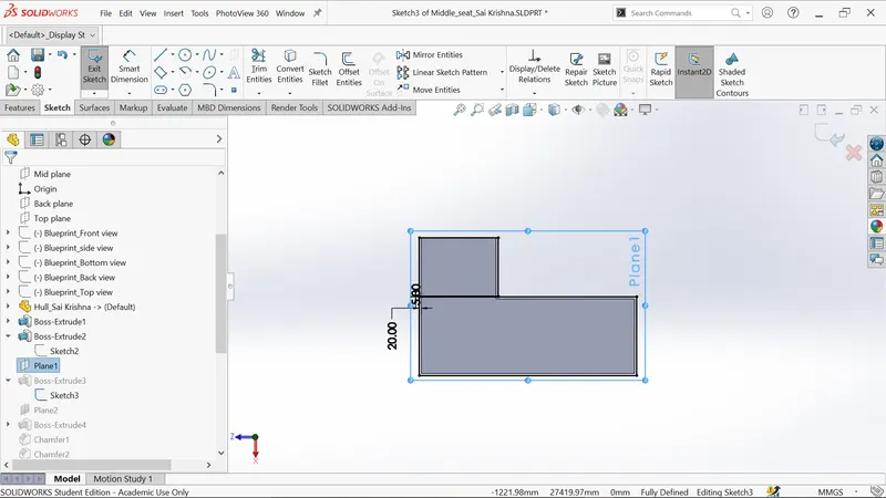
- Sketch on the new plane as shown below.
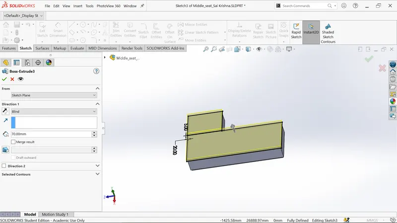
- Create an extrude in upward direction of depth 70mm.
- Create the new plane by selecting pink surface as reference.
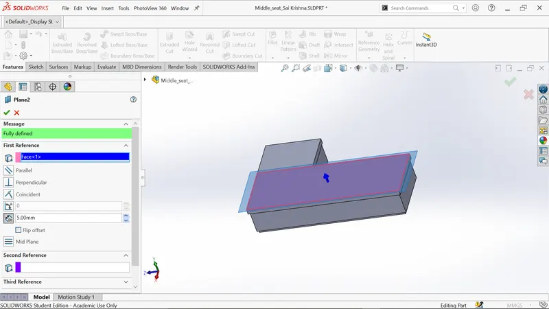
- Sketch on the new plane as per dimensions shown below.
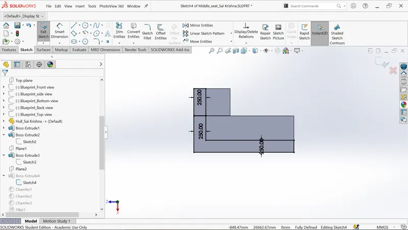
- Create an extrude in upward direction of depth 350mm.
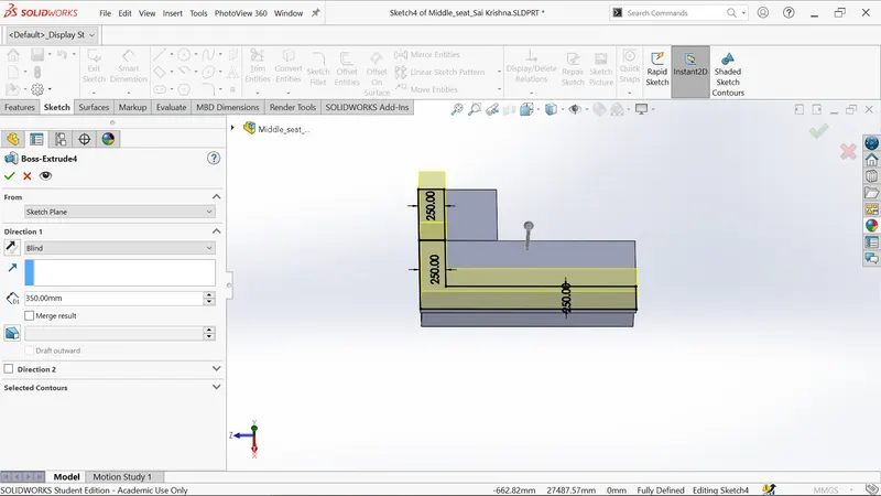
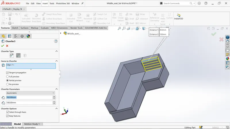
- Apply the distance distance chamfer feature for the blue edge.
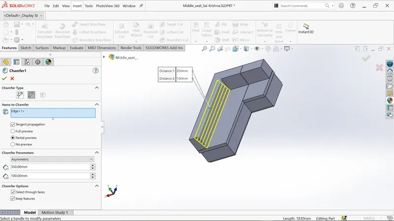
- Apply the distance distance chamfer feature for the blue edge.
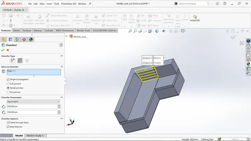
- Apply the distance distance chamfer feature for the blue edge.
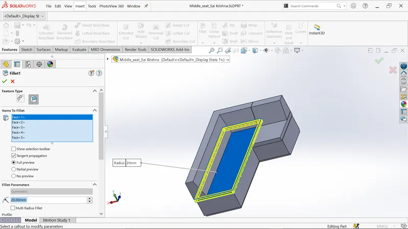
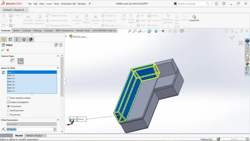
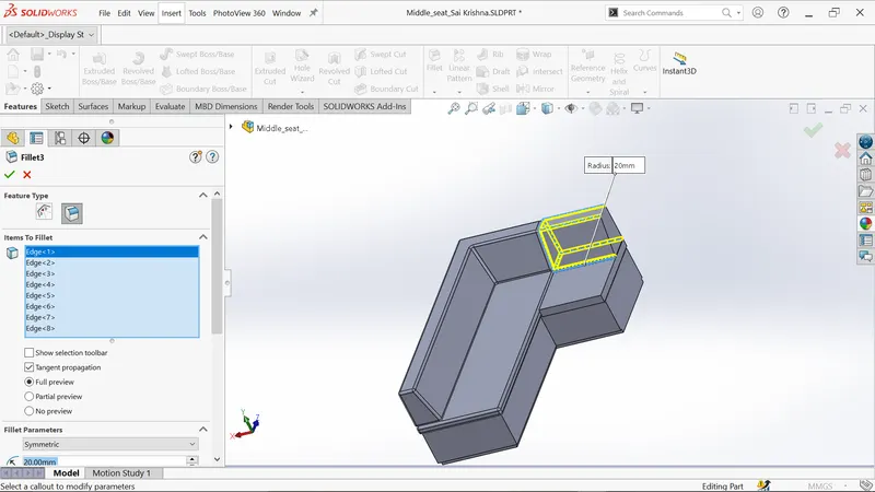
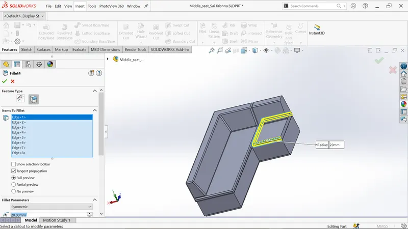
- Apply the fillet as shown below.
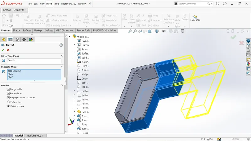
- Mirror the two main bodies of middle seat by selecting blue surface as mirror face.
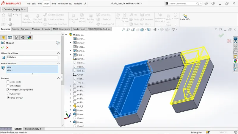
- Mirror the two remaining bodies of middle seat by selecting midplane as mirror face.
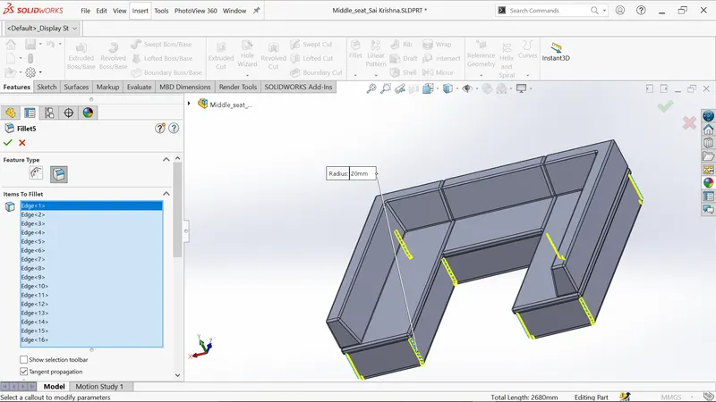
- Add the fillet for edges as shown below.
- Sketch on deck surface and draw corner rectangle as per dimensions.
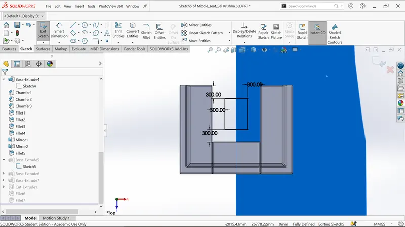
- Extrude in upward direction with depth 20 mm.
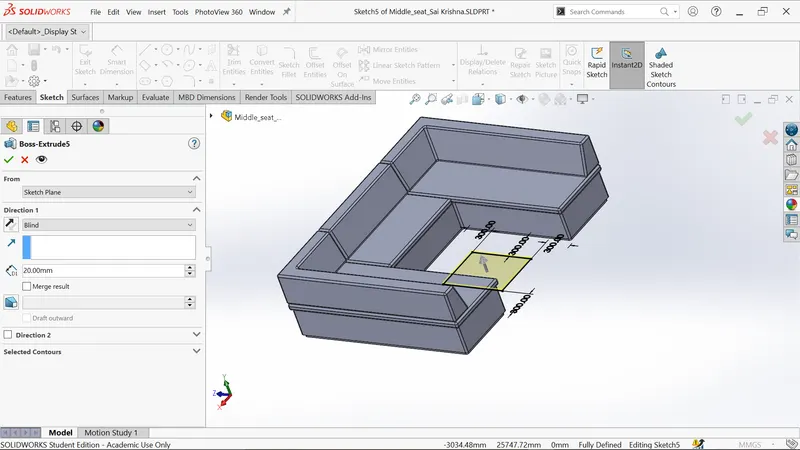
- Select the blue surface and offset the surface of 100 mm.
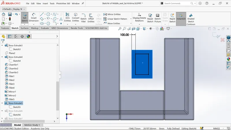
- Extrude in upward direction with depth 550 mm.
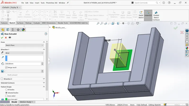
- Select the blue surface and offset the surface of 395 mm.
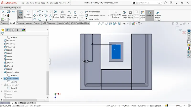
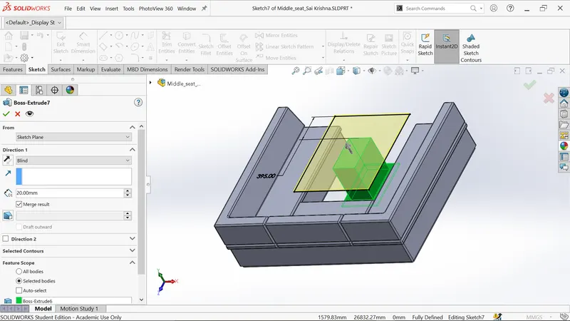
- Extrude in upward direction with depth 20 mm.
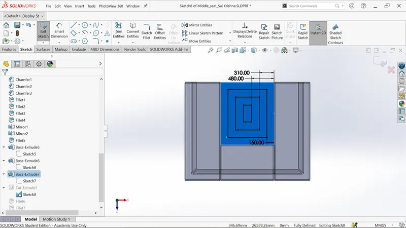
- Select the blue surface and offset the surfaces with distances of 150mm, 310mm,480mm.
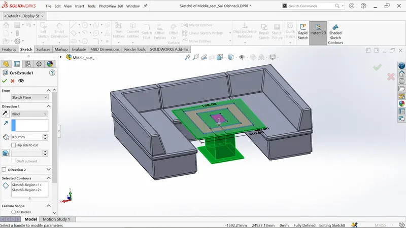
- Perform the cut extrude within inwards of depth 0.5 mm.
- Apply the fillet for following edges as shown in below images.
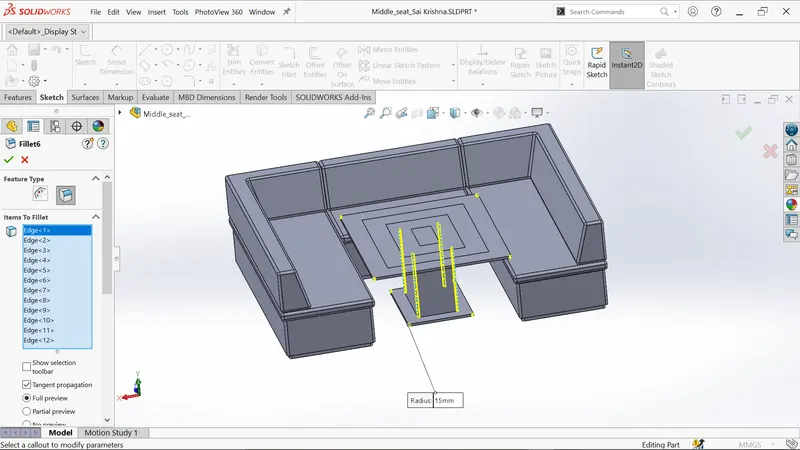
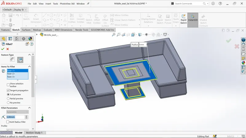
- Apply the appearances for the rear seat,table,tabletop and its surfaces ,pillows.
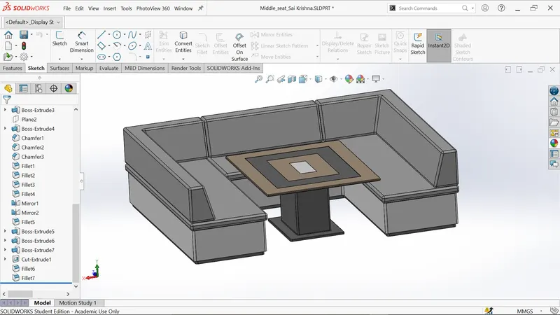
- Finally save the part model as Middle seat.
Views of Middle Seat:
Front view:
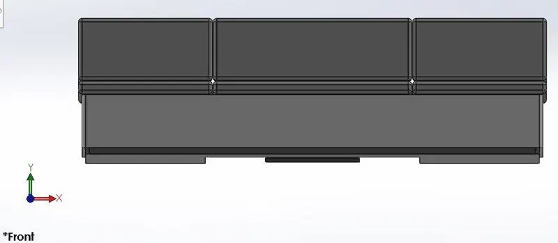
Left view:
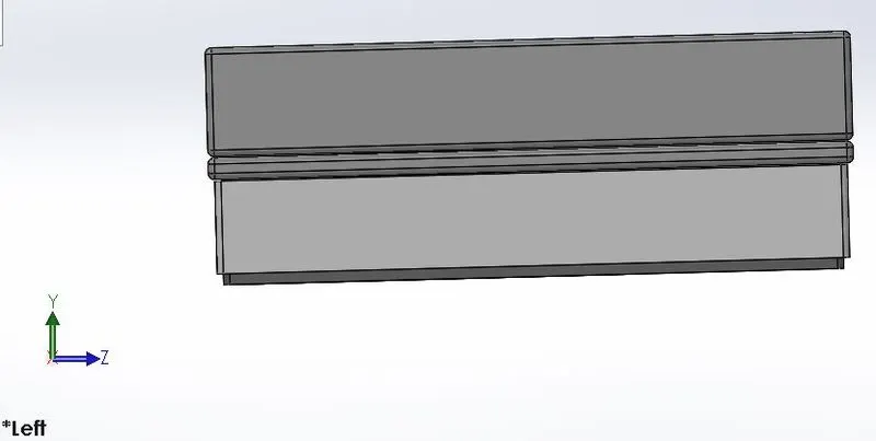
Isometric view:
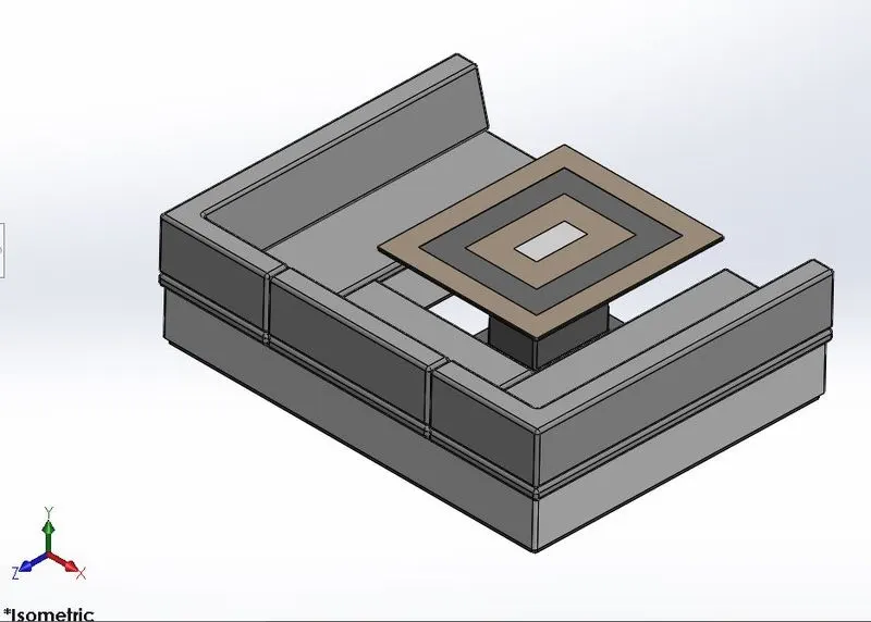
Render image of Middle Seat:
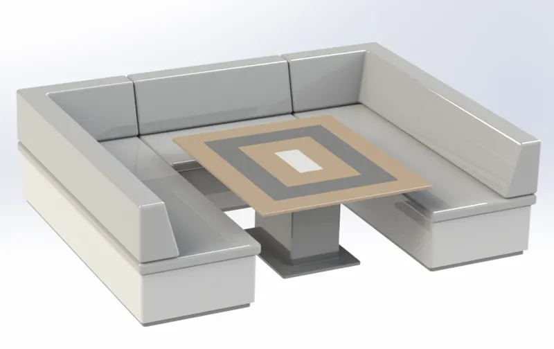
Modelling of Rear Seat
Rear seat is used for resting the passengers on it and it is placed on the rear side yacht.
Features used:
Sketch:Sketch creates 2D drawing for the model of having entities like lines,splines,circles etc.
Sweep Surface: used to sweep the closed profile along a open or closed path to create surface feature.
Surface Offset:Used to create the same surface with some offset distance.
Trim Surface:Used to trim selected surfaces by trim tool.
Ruled Surface:Used for creating ruled surfaces in specified directions from edges.
Knit Surface:Used to combine multiple surfaces into single surface.
Extend Surface:Used to extend the same surface in specified direction.
SurfaceExtrude:Extrude a sketch contours in one or two directions to create surface feature.
Loft Surface:Used to fill gap between two curved surfaces.
Boss Extrude:Used to extrude 2D sketch into 3D body and it can be done in both forward and reverse direcctions.
Cut Extrude:Used to remove material from extrude body.
Chamfer:Used for creating sloping surfaces at edges.
Fillet:Used for creating smooth edges in order to avoid sharp edges.
Sweep Boss:It is used to maake extrude body for sweeping curves.
Mirror:Use to mirror the selected features or bodies.
Procedure to be followed:
- Initially open the blueprint set up file and save as the file as Rear seat.
- Next import the deck surface from the hull by selecting only the surface body.
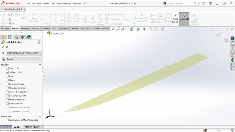
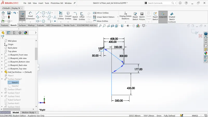
- Sketch on midplane as per dimensions as shown below.
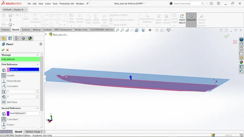
- Create a new plane by selecting pink surface as first reference.
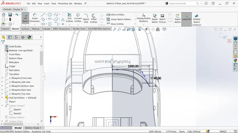
- Create sketch on plane 1 and draw spline of connecting two edges with previous sketch.
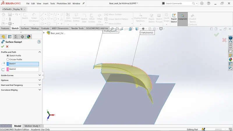
- Create the sweep using sketch1 and sketch2.
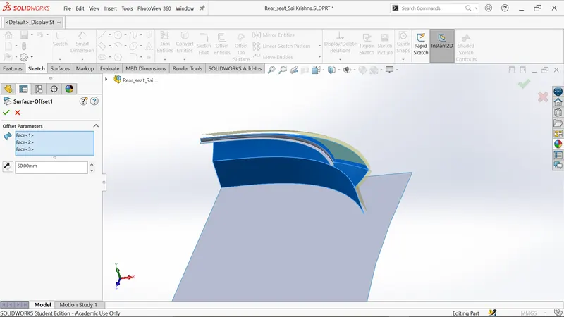
- Offset the surface with 50 mm as shown below.
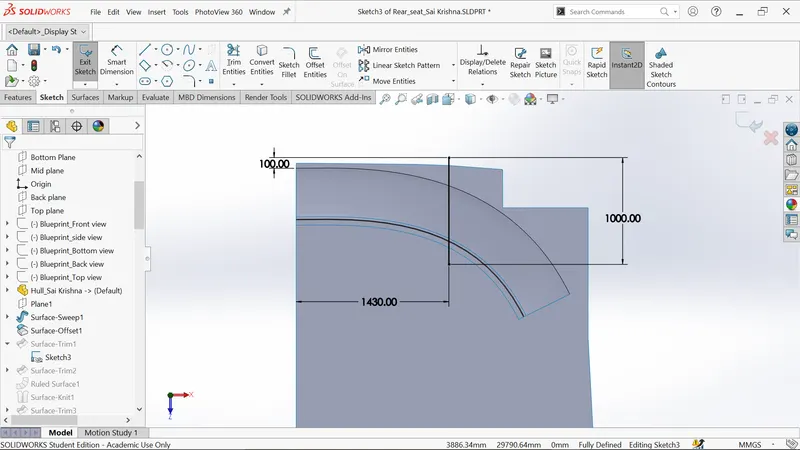
- Create sketch on plane 1 and draw line as view from top view.
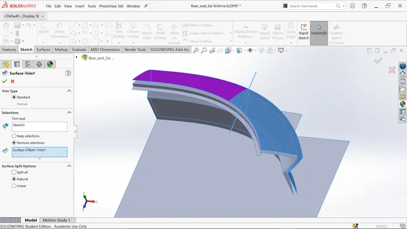
- Trim the purple surface area by selecting sketch3 as trim tool.
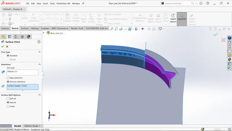
- Trim the purple surface area as shown below.
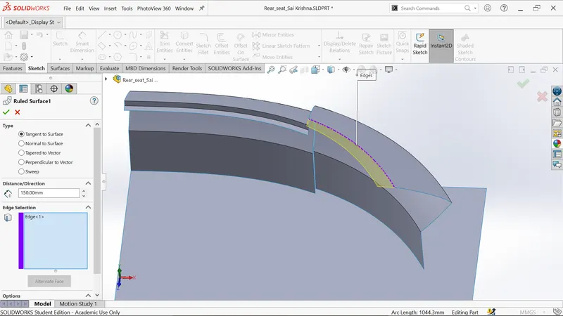
- Create the ruled surface for the selected edge of distance 150 mm.
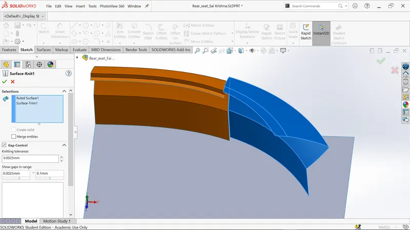
- Knit the two blue surfaces.
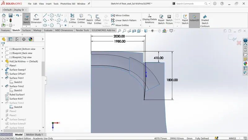
- Create sketch on plane 1 and draw spline as view from top view.
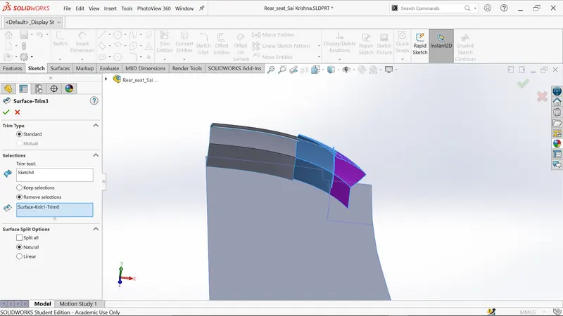
- Trim the purple surface area by selecting sketch4 as trim tool.
- Create a new plane2 as shown below.
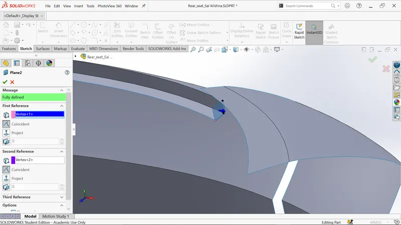
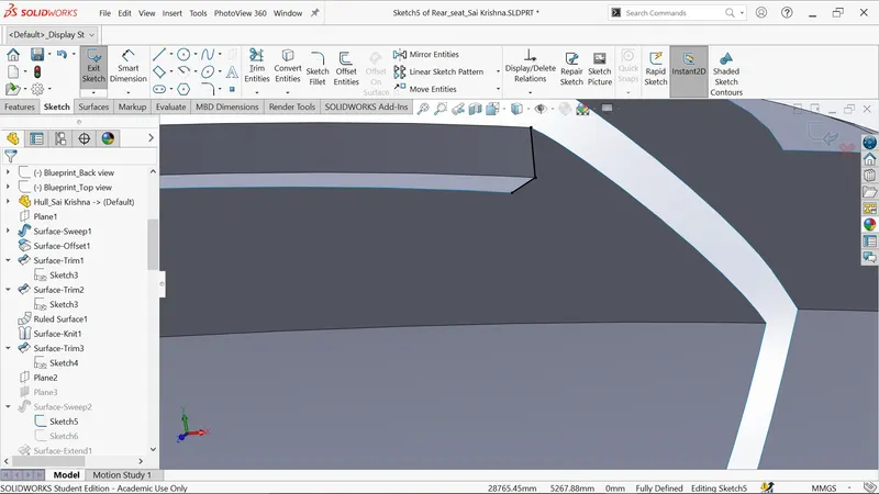
- Sketch on new plane2 and convert the edges as shown.
- Create a new plane3 as shown below.
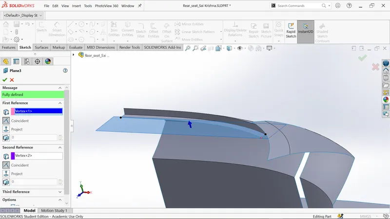
- Create sketch on plane3 and draw spline as view from top view.
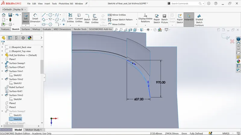
- Create the sweep using sketch5 and sketch6.
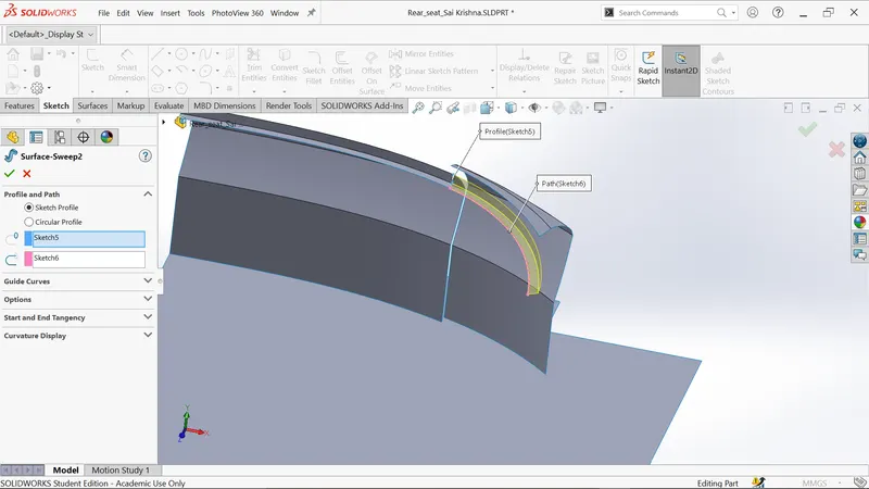
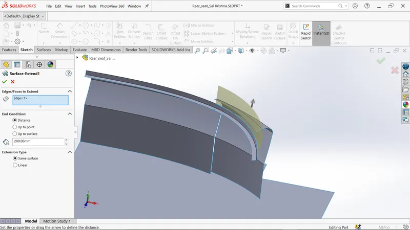
- Extend the selected edge of distance 200 mm.
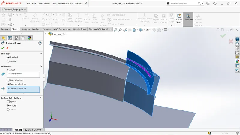
- Trim the purple surface area by selecting surface extend1 as trim tool.
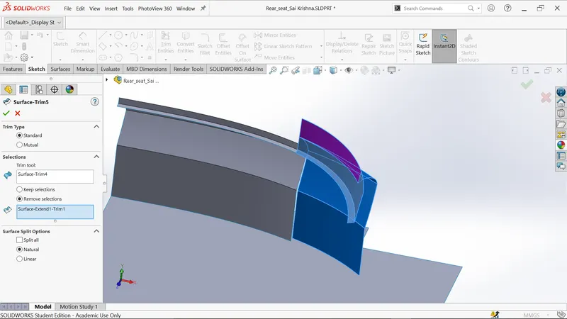
- Trim the purple surface area by selecting surface trim4 as trim tool.
- Knit the two blue surfaces.
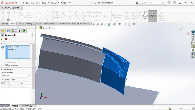
- Trim the purple surface as shown below.
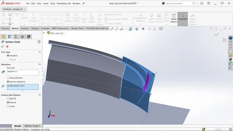
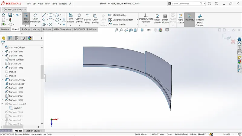
- Sketch on deck surface and convert edge as shown.
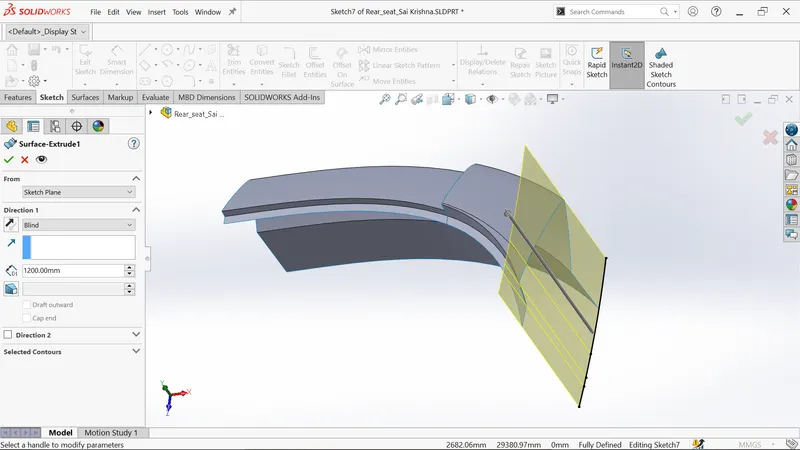
- Extrude the surface of distance 1200 mm as shown below.
- Trim the unwanted portion as shown below.
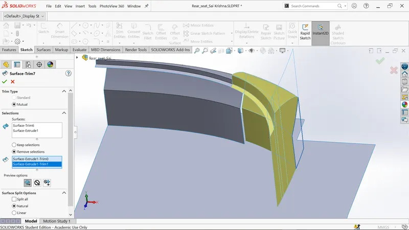
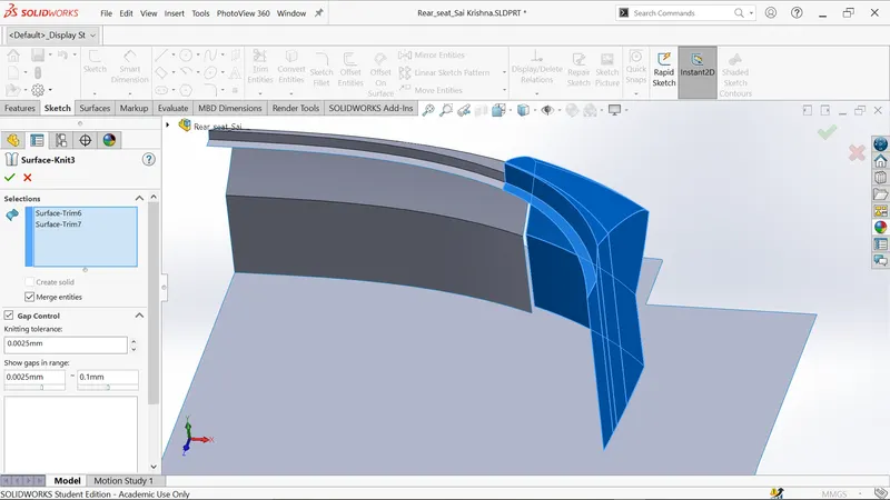
- Knit the two blue surfaces.
- Select the 3D sketch and convert the three black edges as shown below.
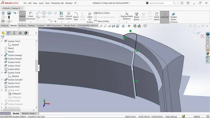
- Select the 3D sketch and convert the three black edges as shown below.
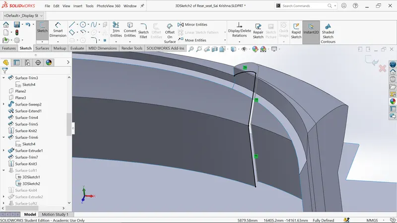
- Create a lofted surface by using 3D sketch1 and 3D sketch2.
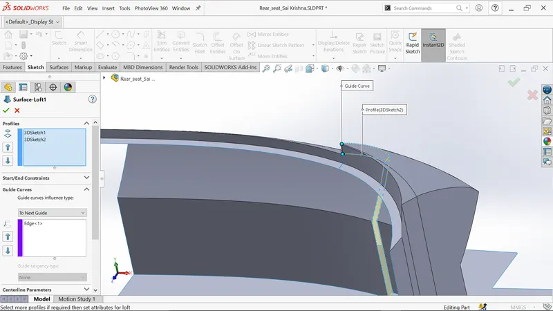
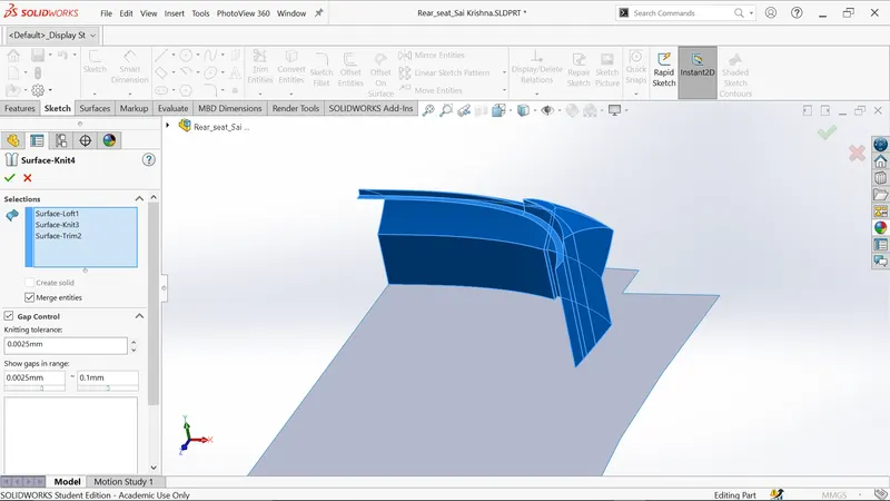
- Knit the three blue edges.
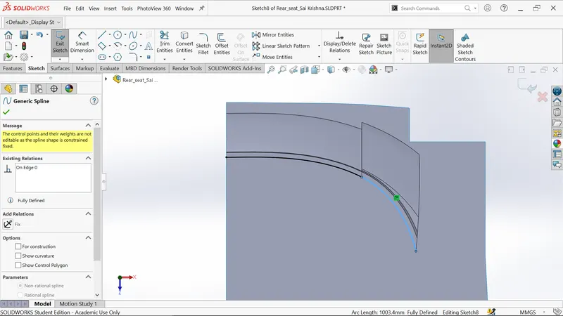
- Sketch on deck surface and convert the edges as shown.
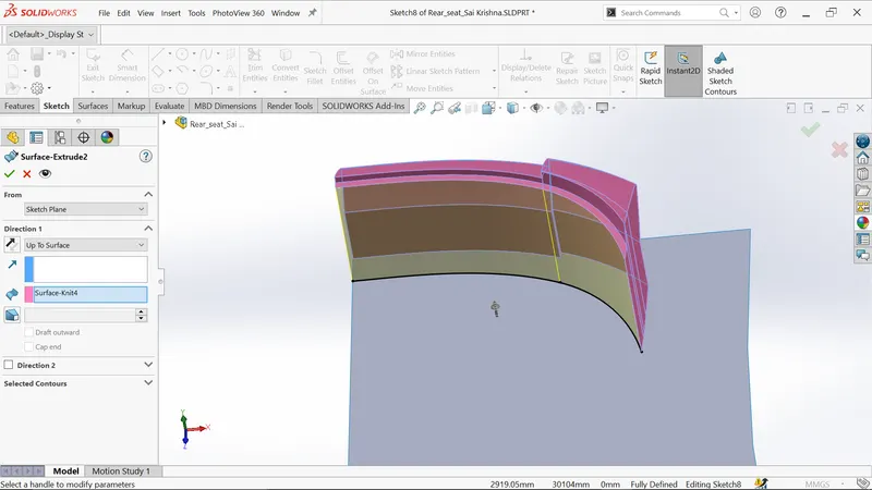
- Create the surface extrude upto pink surface.
- Create the 3D sketch and convert the three black edges.
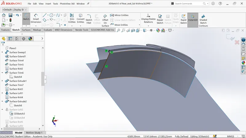
- Create the 3D sketch and convert the three black edges.
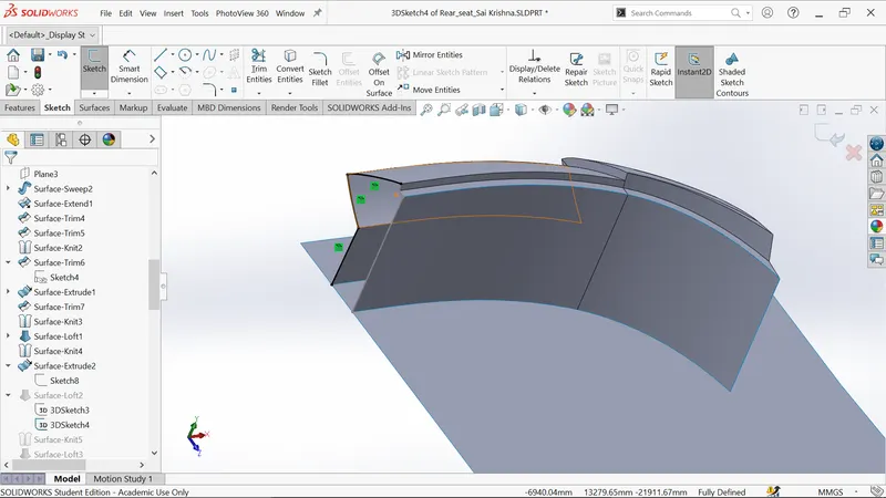
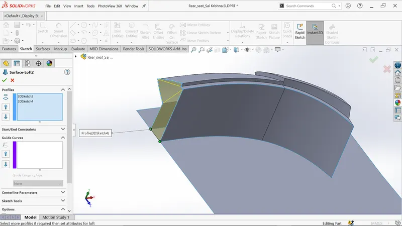
Create a lofted surface by using 3D sketch3 and 3D sketch4.
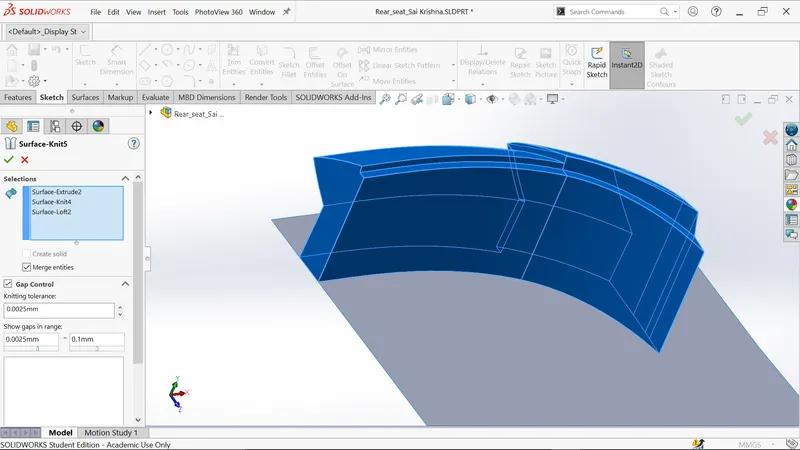
- Knit the three blue surfaces.
- Create a lofted surface by selecting edge1 and edge2 as shown.
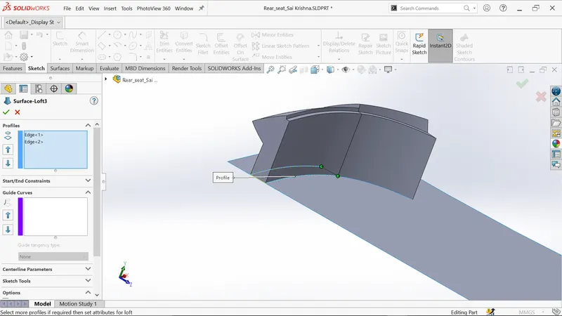
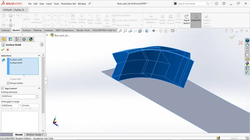
- Knit the two blue surfaces.
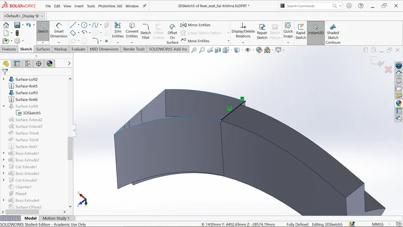
- Create the 3D sketch and convert the two black edges.
- Create a lofted surface by selecting edge1 and edge2 as shown.
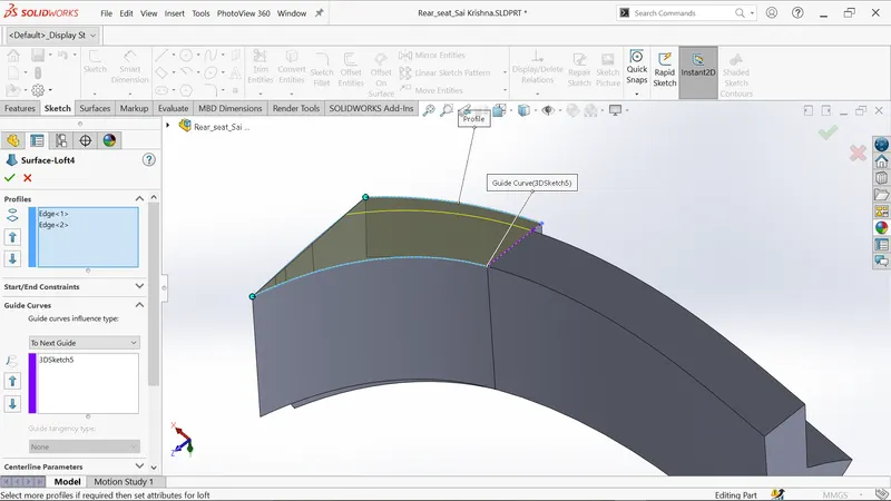
- Extend the surface of loft 4 in order to fill the gap.
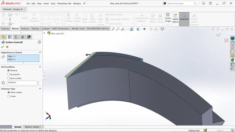
- Extend the surface extrude1 to fill the gap.
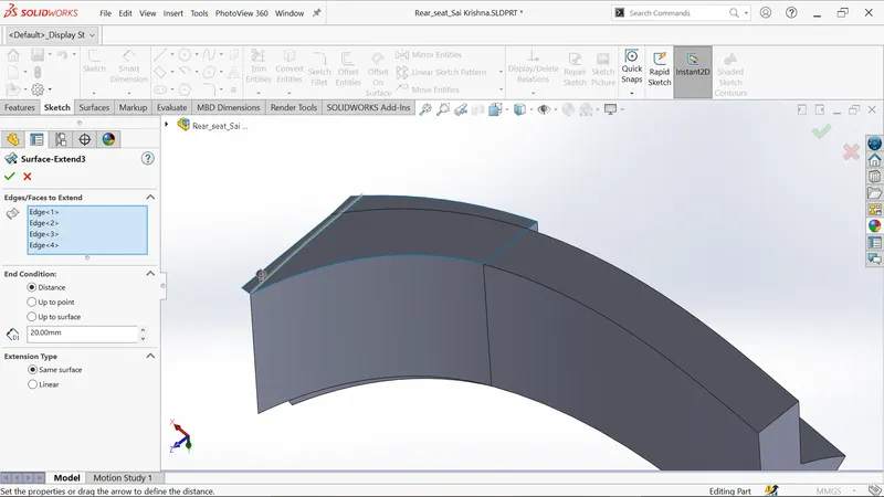
- Trim the purple surfaces as shown below.
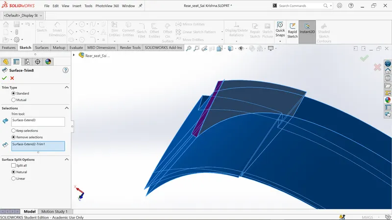
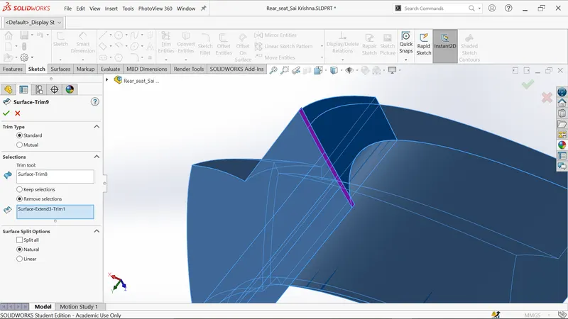
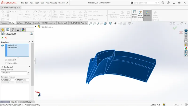
- Knit the two blue surfaces.
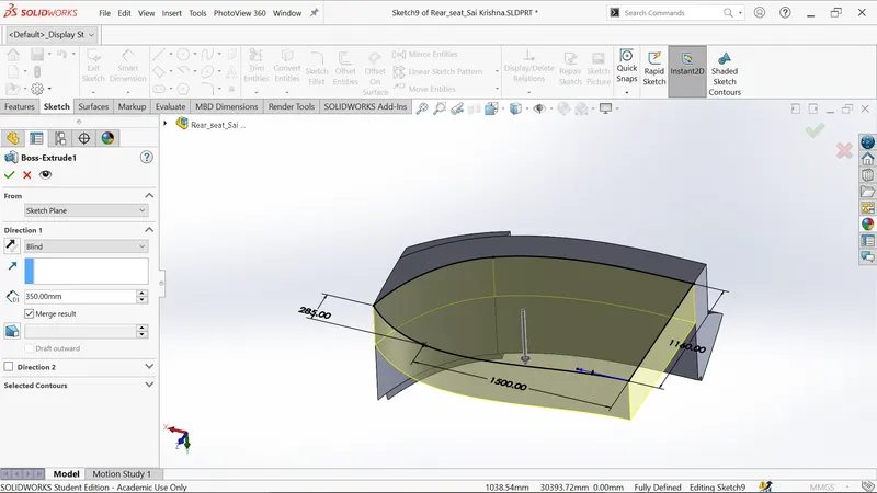
- Sketch on deck surface and extrude them as shown below.
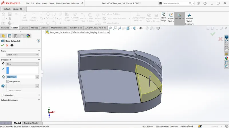
- Sketch on extruded surface as shown below and extrude upwards of depth 310 mm.
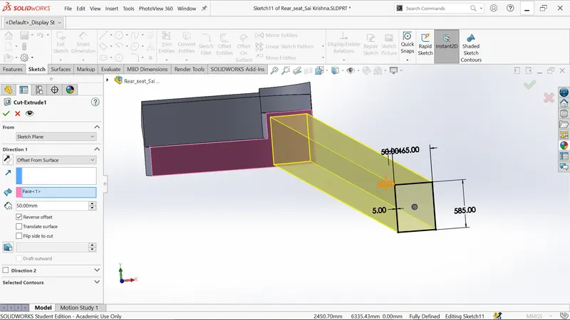
- Sketch on the front plane as per dimensions as shown below and extrude outwards of 50 mm by offset from pink surface.
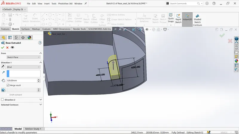
- Sketch on surface as shown and extrude them as shown below.
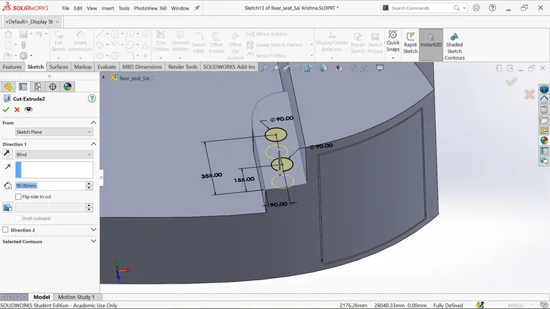
- Sketch two circles on surface as shown and cut extrude them with depth 90mm.
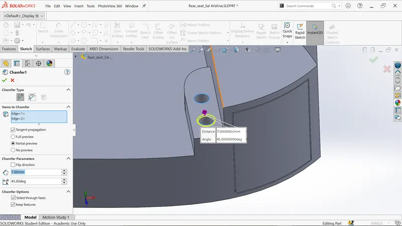
- Add the angle distance distance chamfer.
- Create the new plane as shown.
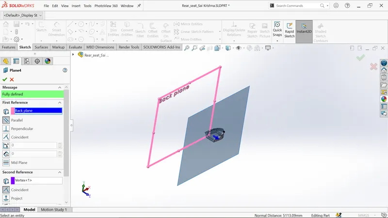
- Create the sketch on plane4 as per dimensions as shown below and extrude from the pink face.
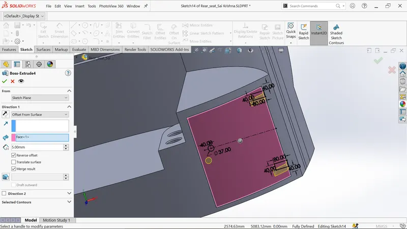
- Offset the surface of 5mm.
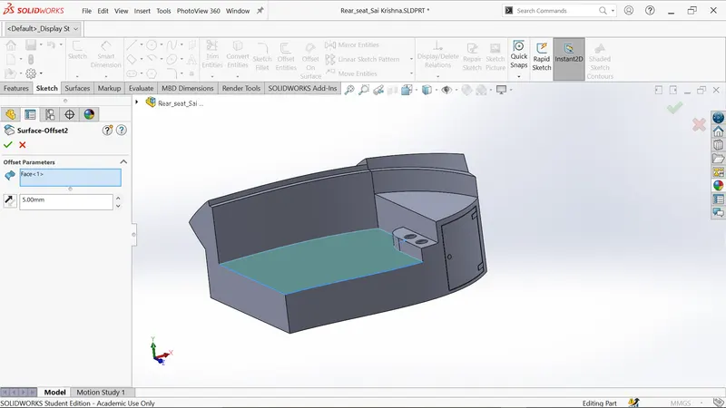
- Create the sketch on surface by selecting surface offset with 2.5mm.
- Trim blue surfaces as shown below.
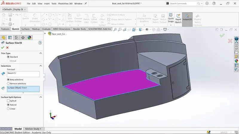
- Create the sketch on surface by converting the surface and extrude outwards of 60 mm.
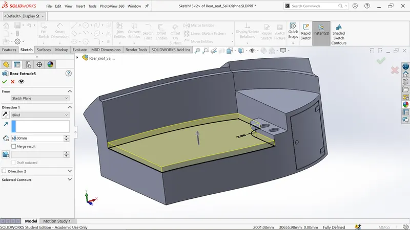
- Create surface offset of 5mm depth.
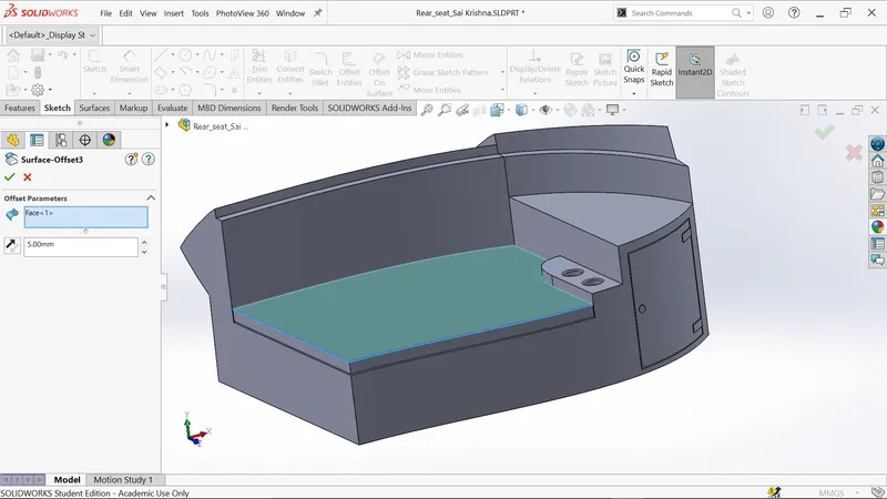
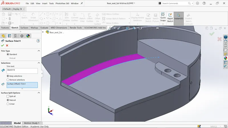
- Create the 2D sketch on surface as shown as blue line.
- Trim the surface using above sketch as trim tool.
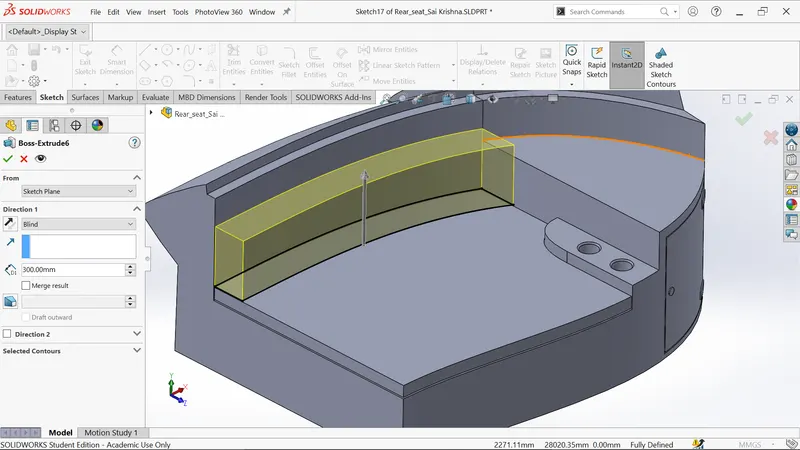
- Create the 2D sketch on surface and convert the edges as shown below and extruded outwards of 300mm.
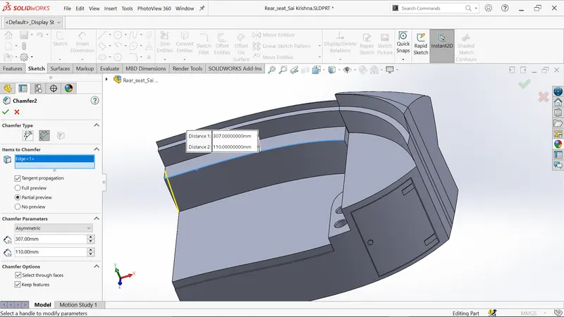
- Add the distance distance chamfer for the edge.
- Add the fillet for 4 edges as shown.
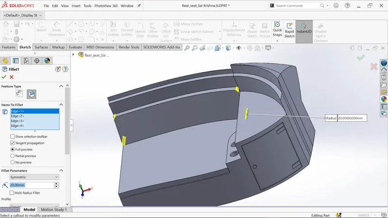
- Similarly create fillet for all edges.
- Create new sketch on plane4 and draw corner rectangle and extrude as shown below
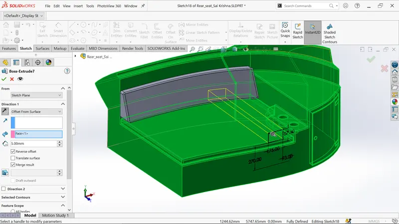
- Create new sketch on plane4 again and offset the surface with 5mm and extrude as shown below
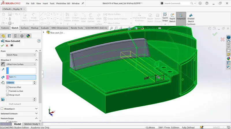
- Add the fillet for the edges as below.
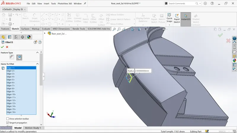
- Create new sketch on deck surface and draw line as shown in figure.
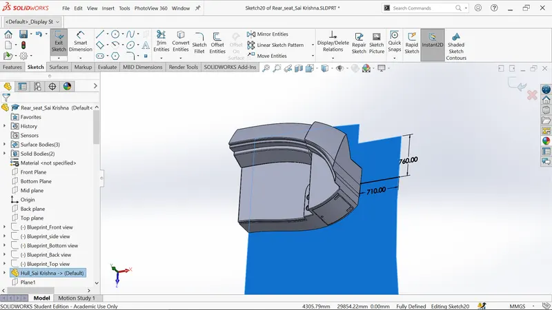
- Create the new plane5 as shown.
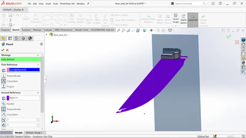
- Create new sketch on plane5 and draw lines as shown in figure.
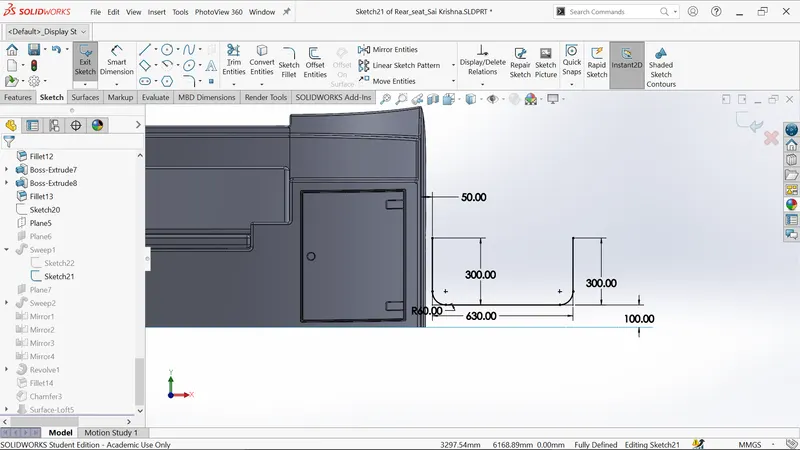
- Create the new plane6 as shown.
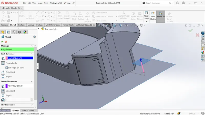
- Create new sketch on plane6 and draw circle as shown in figure.
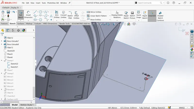
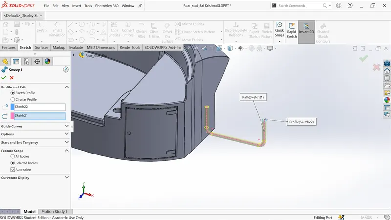
- Create a sweep using sketch21 and sketch22.
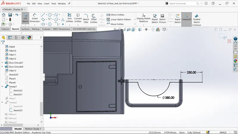
- Create new sketch on plane5 and draw lines,half circle as shown in figure.
- Create the new plane7 as shown.
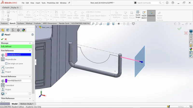
- Create new sketch on plane7 and draw circle as shown in figure.
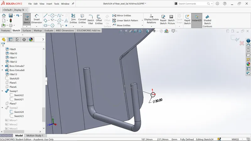
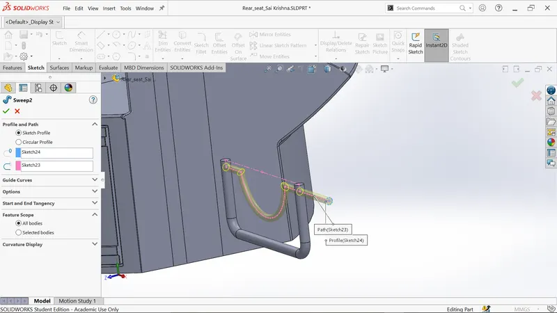
- Create sweep using sketch23 and sketch24.
- Mirror the railing as shown.
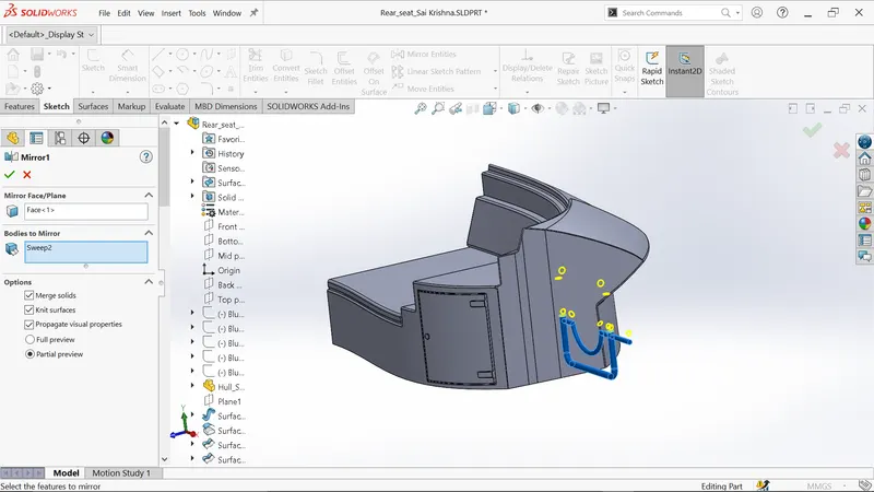
- Mirror the rear seat as shown.
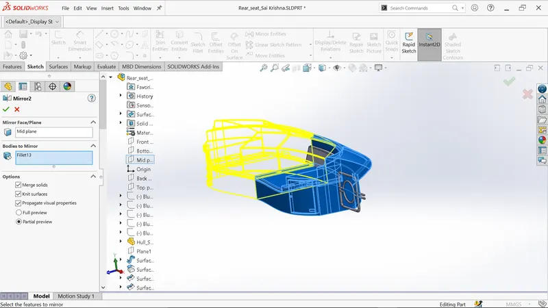
- Mirror the pillow as shown.
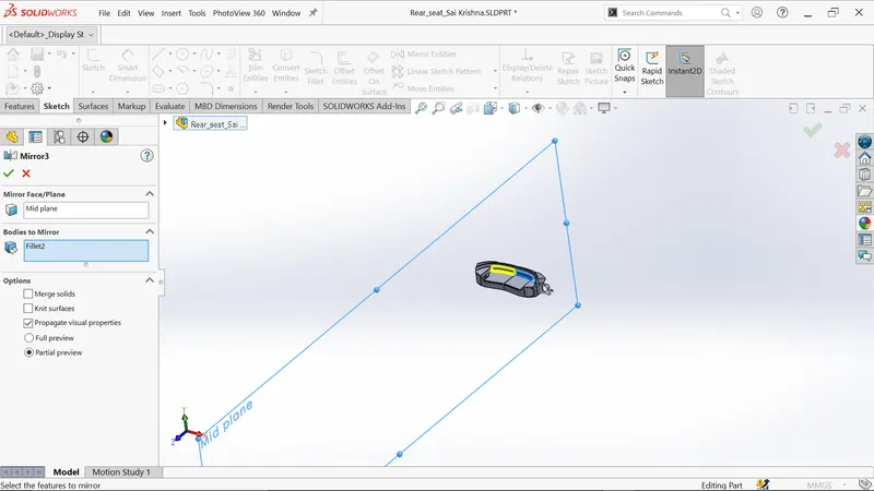
- Mirror the remaining railing as shown.
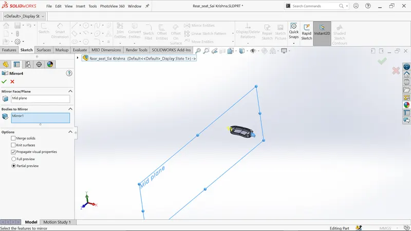
- Create sketch on midplane and draw the lines for flagstaff as shown below.
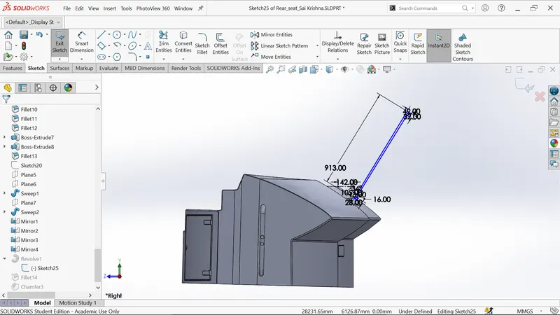
- Create the revolve by selecting blue line as axis
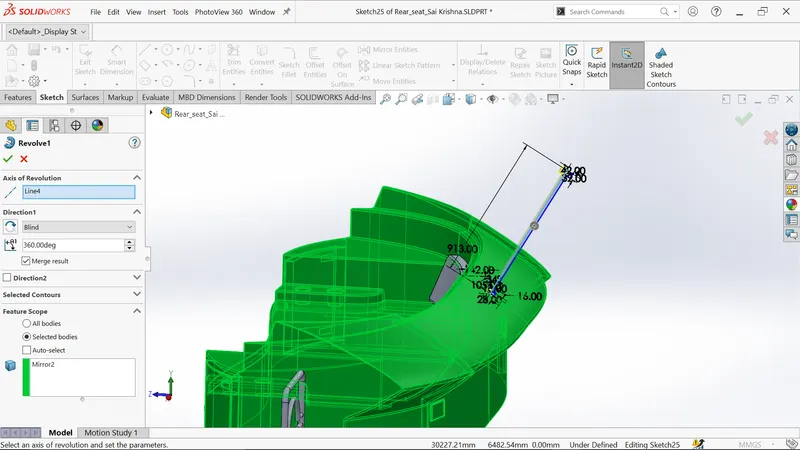
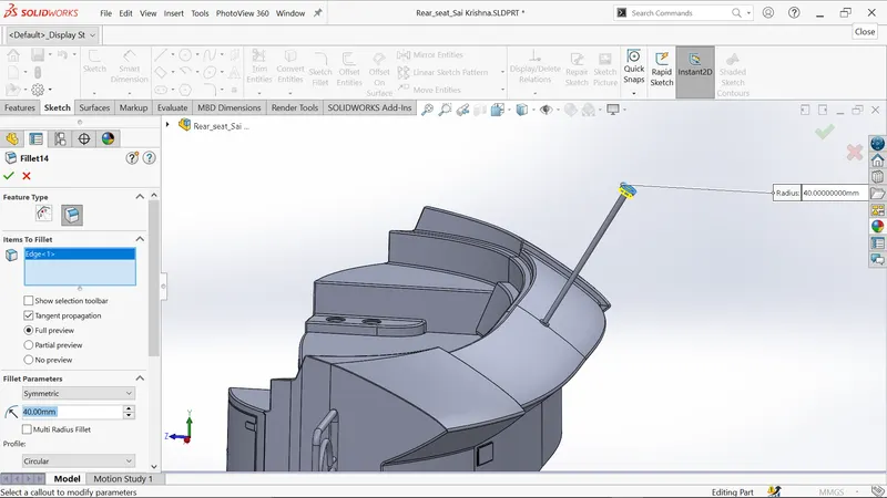
- Applty the fillet at outer edge of 40mm.
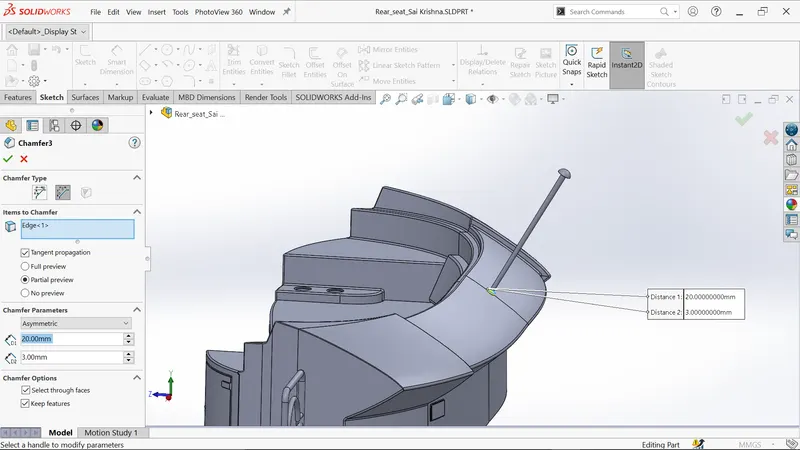
- Applty the distance chamfer at edge as shown.
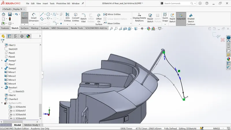
- Create the four 3D sketches and draw splines to complete flag profile as shown.
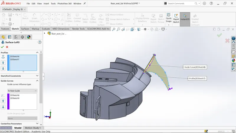
- Loft the surfaces by using above four 3D sketches.
- Add the appearances for flagstaff ,flag, locks and hinges, pillows, rear seat and lights.
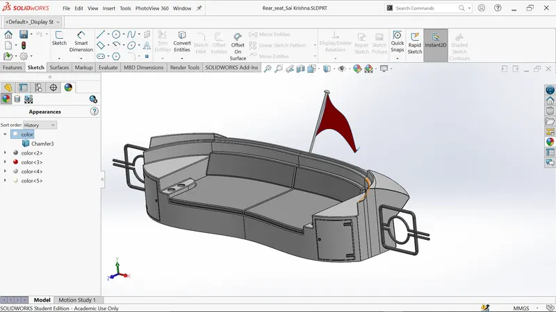
- Finally save the part model as Rear seat.
Views of RearSeat:
Front view:
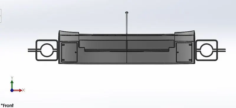
Right view:
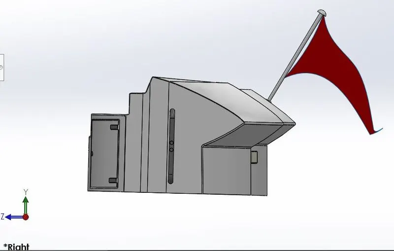
Isometric view:
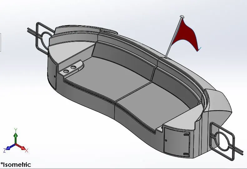
Render image of Rear Seat:
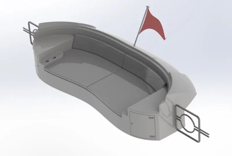
Modelling of Superstructure
Superstructure is the decked structure on the ship extended from front of ship to almost to the rear side.It is situated on the decked surface of the hull and it having the main control room of the ship.
Features used:
Sketch:Sketch creates 2D drawing for the model of having entities like lines,splines,circles etc.
SurfaceExtrude:Extrude a sketch contours in one or two directions to create surface feature.
Sweep Surface:used to sweep the closed profile along a open or closed path to create surface feature.
Knit Surface:Used to combine multiple surfaces into single surface.
Ruled Surface:Used for creating ruled surfaces in specified directions from edges.
Trim Surface:Used to trim selected surfaces by trim tool.
Project curve:Used to project the two sketches into single curve.
Loft Surface:Used to fill gap between two curved surfaces.
Filled Surface:This feature is used to fill the surface material in between two surfaces.
3D Sketch:Used to create sketch entities in 3D environment.
Extend Surface:Used to extend the same surface in specified direction.
Boss Extrude:Used to extrude 2D sketch into 3D body and it can be done in both forward and reverse direcctions.
Cut Extrude:Used to remove material from extrude body.
Delete Face:Used to delete the selected faces.
Surface Offset:Used to create the same surface with some offset distance.
Dome:Used to create concave shape on surface.
Fillet:Used for creating smooth edges in order to avoid sharp edges.
Split Line:Used for projecting entities on planar or curves surfaces.
Mirror:Use to mirror the selected features or bodies.
Chamfer:Used for creating sloping surfaces at edges.
Procedure to be followed:
- Initially open the blueprint set up file and save the file as Superstructure.
- Next import the deck surface from the hull by selecting only the surface body.
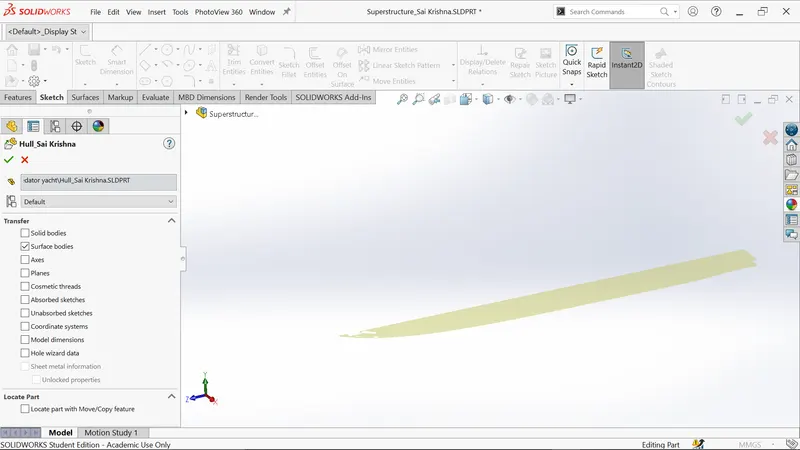
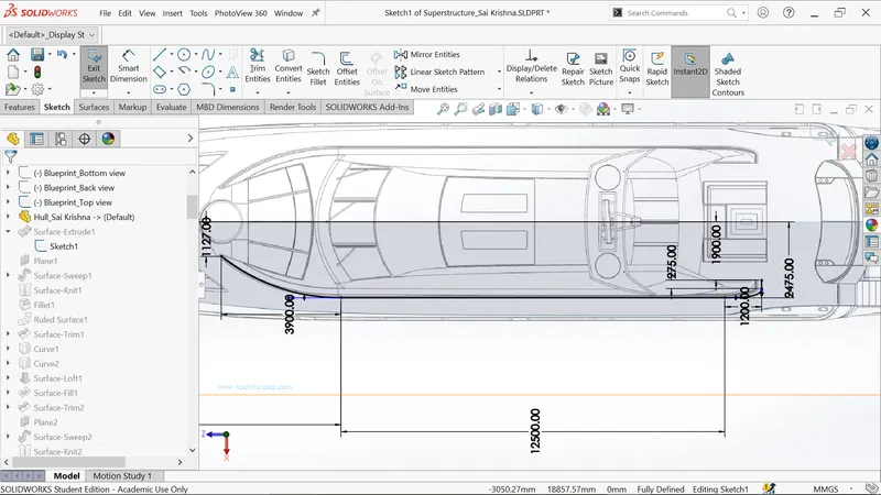
- Create the sketch on deck surface and draw line,spline as per dimensions as shown below.
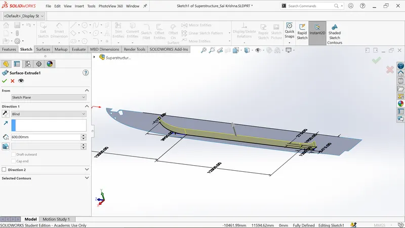
- Extrude the sketch1 using surface extrude feature.
- Create a new plane as shown below.
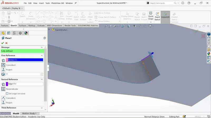
- Sketch on the new plane1 and draw straight line as shown.
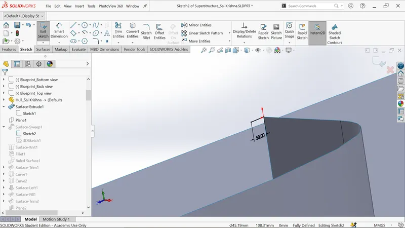
- Select 3D sketch and convert the upper edges of surface extrude.
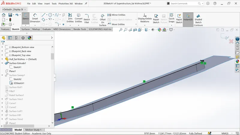
- Create sweep surface using sketch1 and 3Dsketch1.
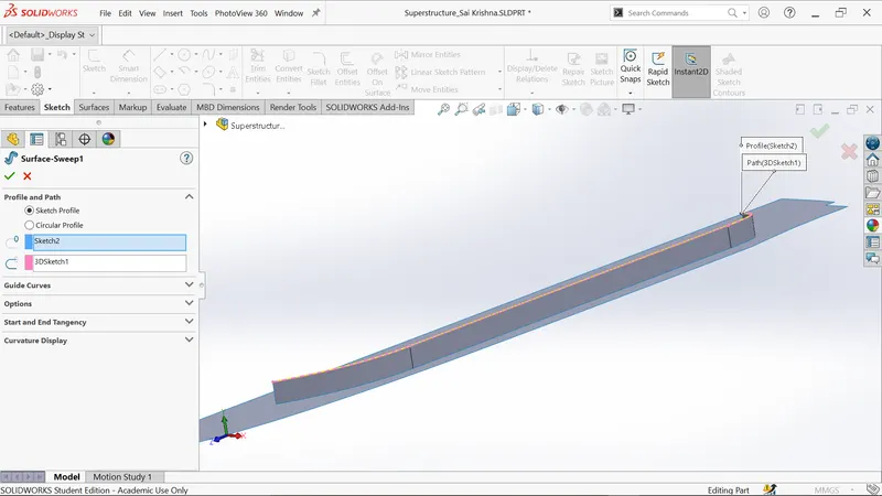
- Knit the two blue surfaces.
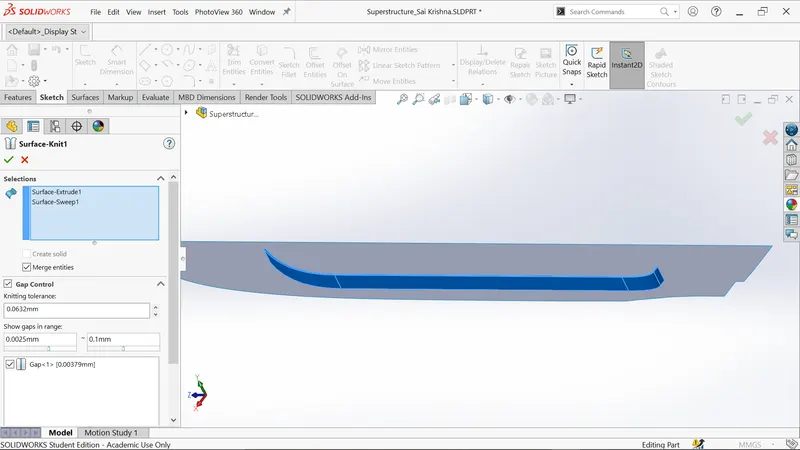
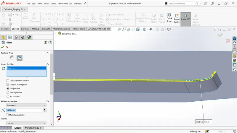
- Add the fillet on the blue edge of 35 mm.
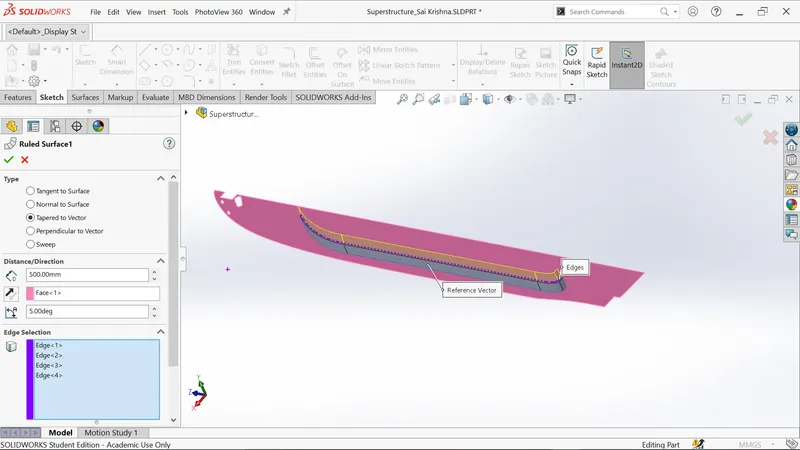
- Generate a ruled surface for selected edges using pink surface as reference vector as shown below.
- Make sure the ruled surface is inwards.
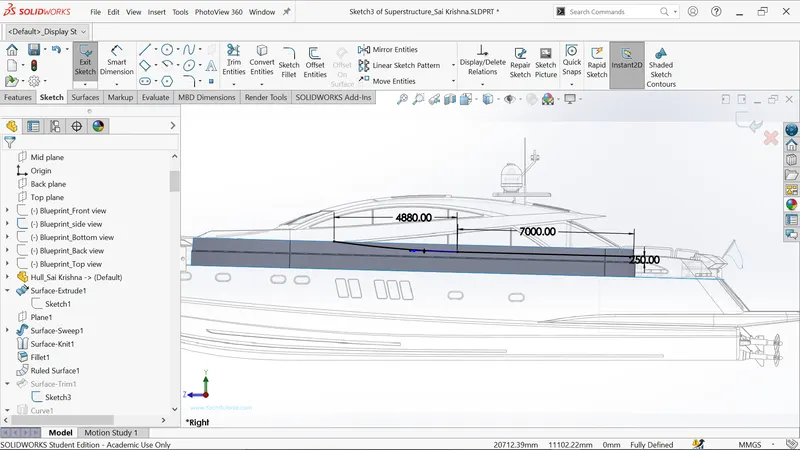
- Sketch on the midplane and draw a line,spline and are tangent to each other as shown.
- Trim purple surface by selecting sketch3 as trim tool.
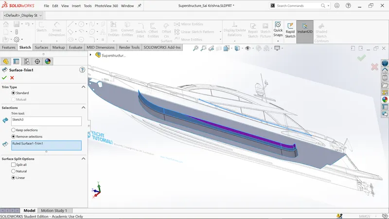
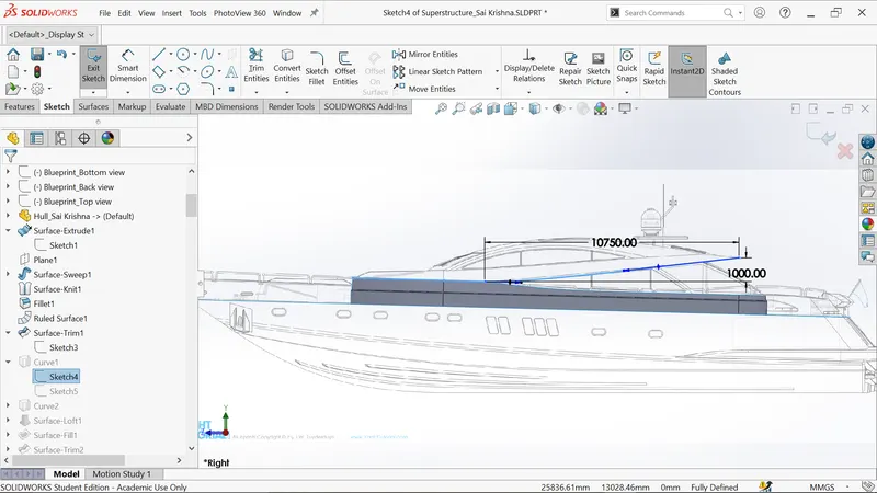
- Sketch on midplane and convert two upper edges.
- Draw the spline as connecting with convert line as shown below.
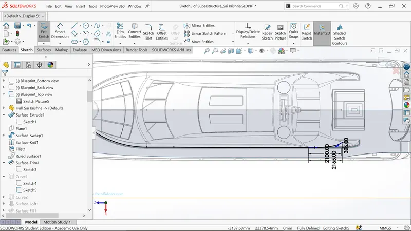
- Sketch on top plane and convert four inner edges.
- Draw the spline as shown below.
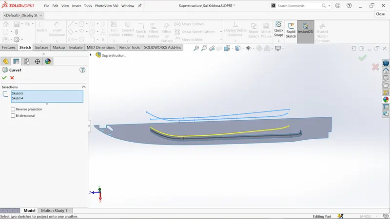
- Project the sketch5 and sketch6 using project curve feature.
- Sketch on top plane and offset the edges with distance 200mm..
- Draw the spline as shown below.
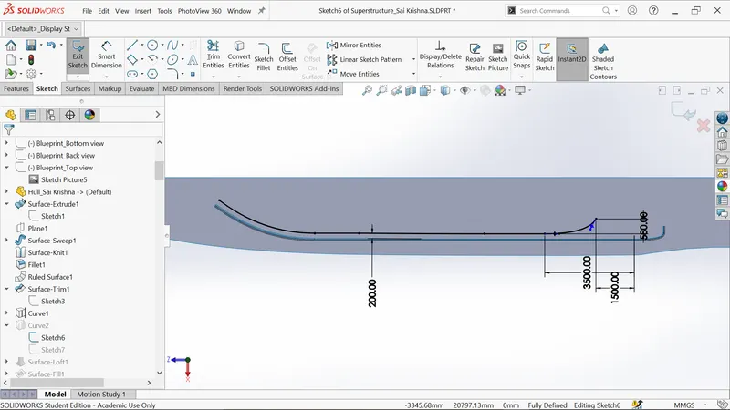
- Sketch on midplane and draw two lines.
- Draw the spline connecting in between two lines as shown below.
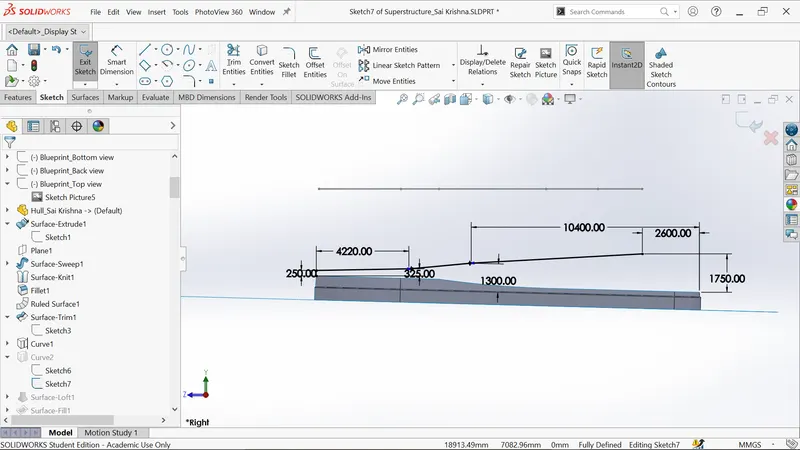
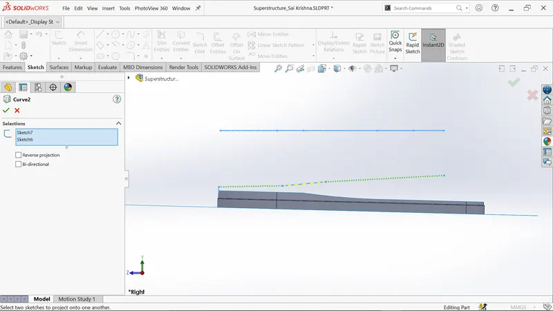
- Project the sketch6 and sketch7 using project curve feature.
- Create 3D sketch and draw line of connecting with front of curve1 and curve2.
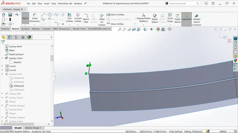
- Create 3D sketch and draw line of connecting with back of curve1 and curve2.
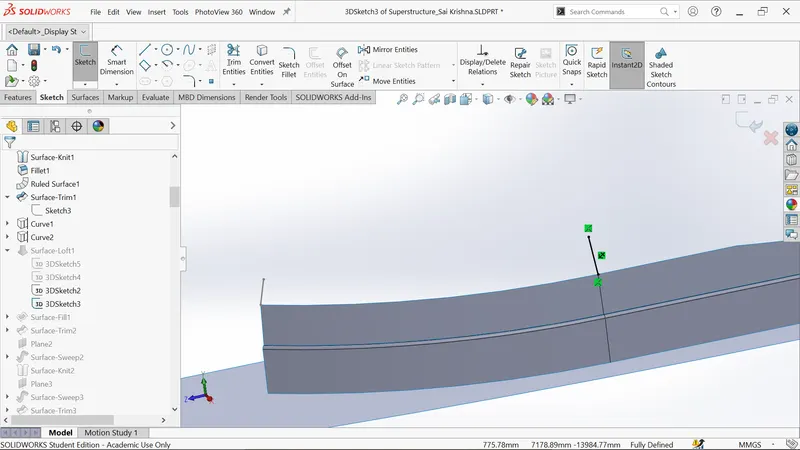
- Create 3D sketch and convert curve2 and trim extra lines.
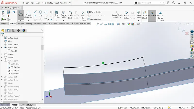
- Create 3D sketch and convert curve1 and trim extra lines.
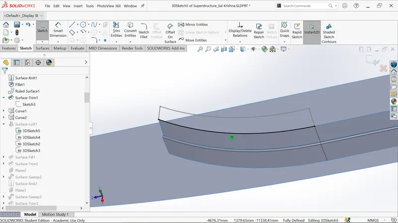
- Generate the lofted surface using 3D sketch4 and 3D sketch5.
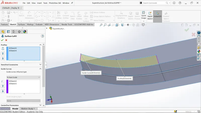
- Create 3D sketch and draw line of connecting end points of curve1 and curve2.
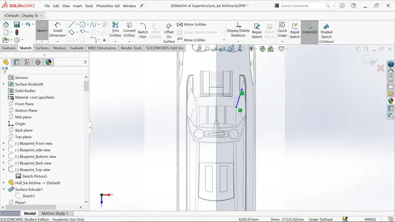
- Create 3D sketch and and convert the curve2 and trim exta lines.
- Draw the spline connecting with convert edge as shown below.
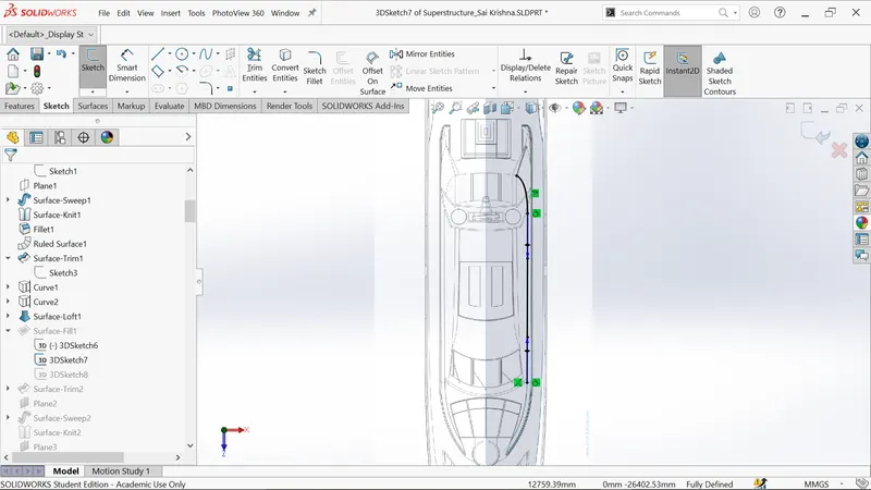
- Create 3D sketch and and convert the curve2 and trim exta lines.
- Draw the spline connecting with convert edge as shown below.
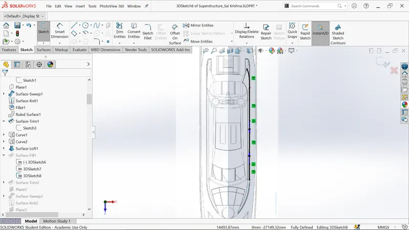
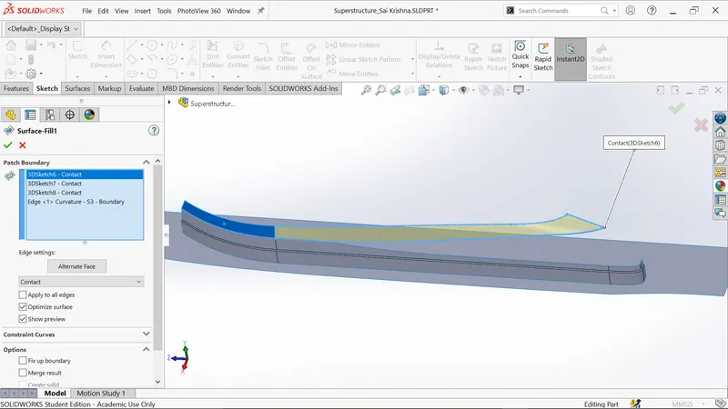
- Fill the surfaces by using fill surface feature of selecting the 3D sketches and edge boundary as shown below.
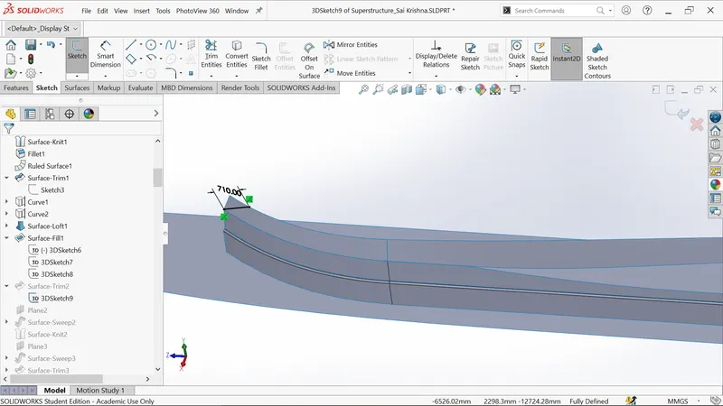
- Create 3D sketch and draw line by adding dimension of 710mm.
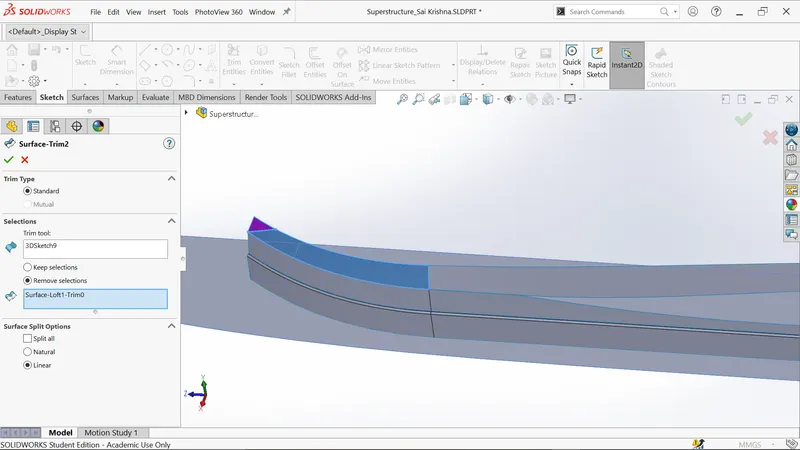
- Trim purple surface by selecting 3Dsketch9 as trim tool.
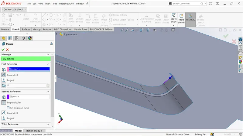
- Create a new plane2 as shown below.
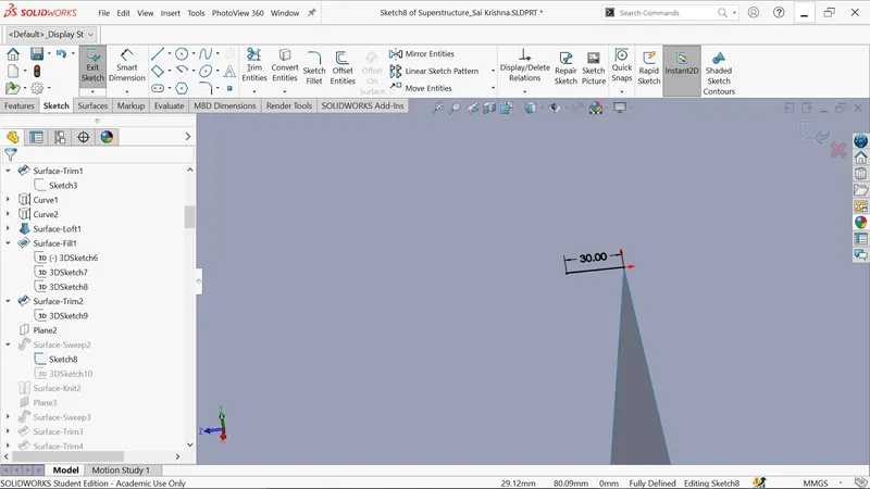
- Create a new sketch on plane2 and draw the horizontal line.
- Create 3D sketch and convert the selected edges as shown.
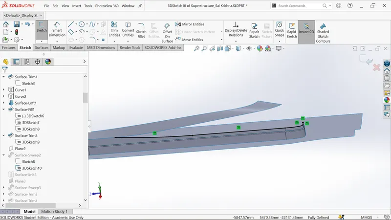
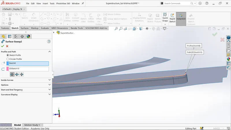
- Generate sweep using 3D sketch10 and sketch8.
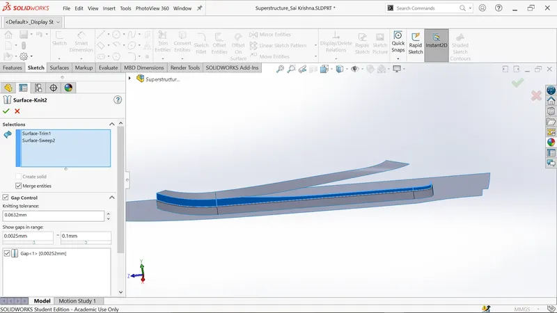
- Knit the two blue surfaces.
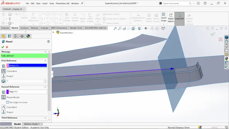
- Create a new plane3 as shown below.
- Create a new sketch on plane3 and draw the spline.
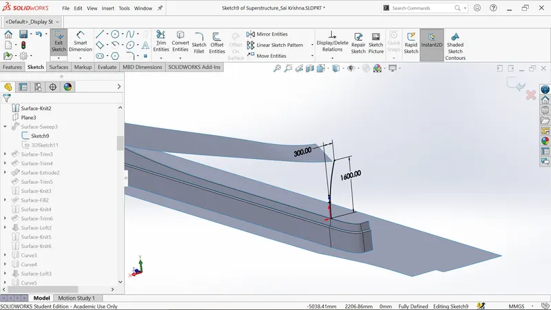
- Create 3D sketch and convert the selected edges as shown.
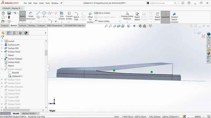
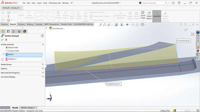
- Generate sweep using 3D sketch11 and sketch9.
- Create sketch on midplane and convert the selected edges as shown.
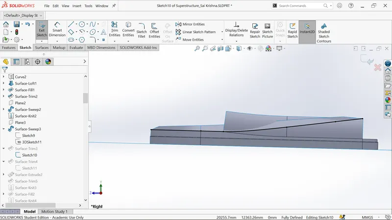
- Trim purple surface by taking sketch10 as trim tool.
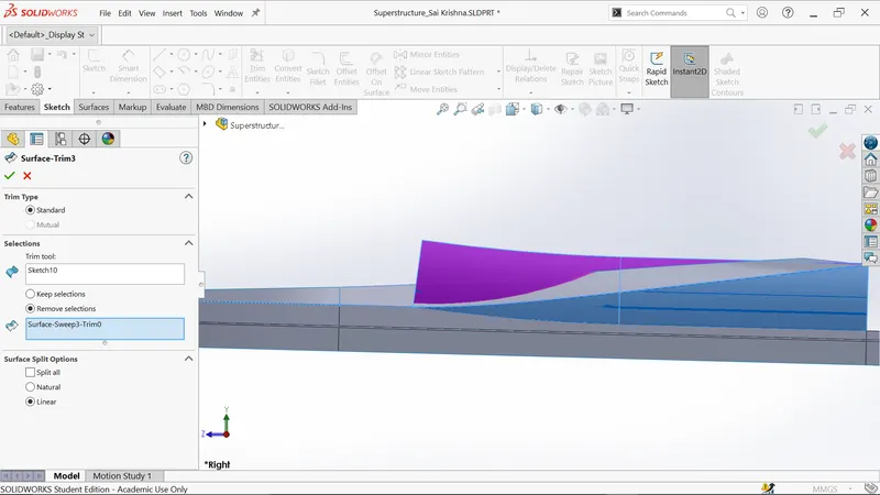
- Create sketch on midplane and draw the spline as shown.
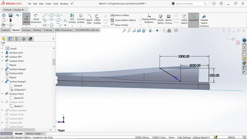
- Trim purple surface by taking sketch11 as trim tool.
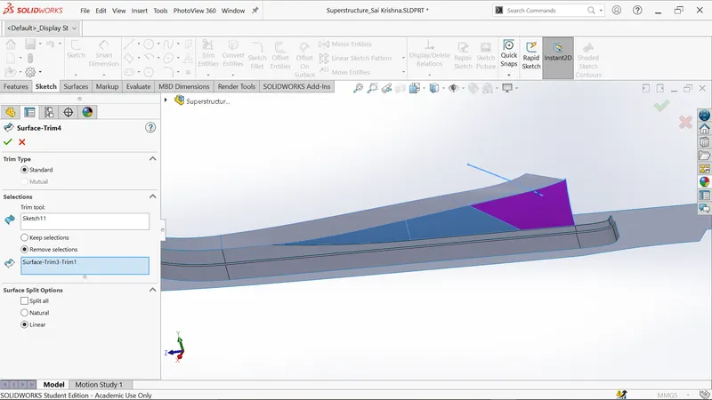
- Create sketch on midplane and convert the selected edges as shown.
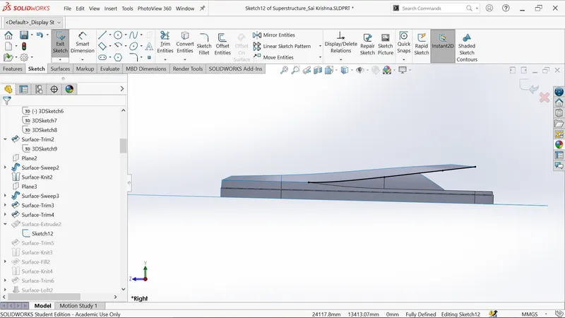
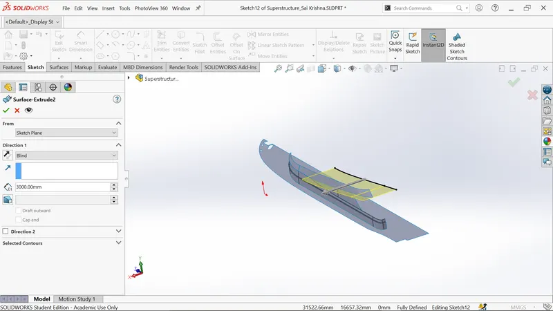
- Extrude the surface with depth 3000mm.
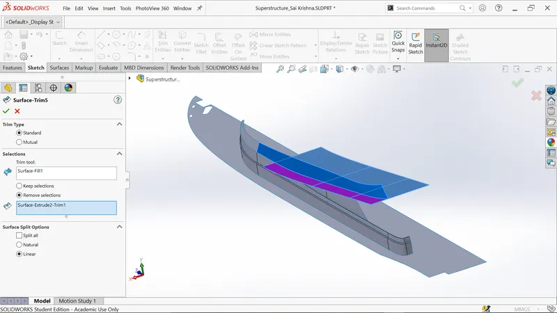
- Trim purple surface by taking surface fill1 as trim tool.
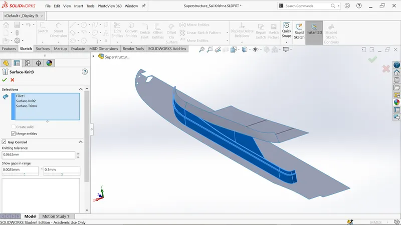
- Knit the blue surfaces as shown below.
- Create a new 3D sketch and draw the line.
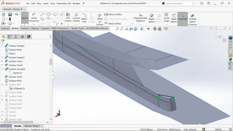
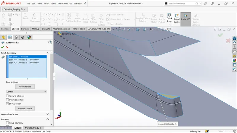
- Fill the surface by selecting the edges as shown.
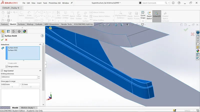
- Knit the blue surfaces as shown below.
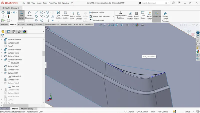
- Draw the spline on surface as shown below.
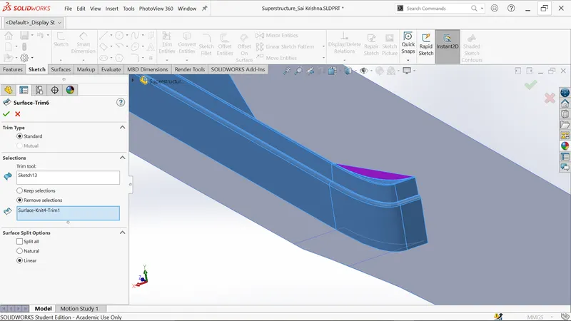
- Trim purple surface by taking sketch13 as trim tool.
- Create sketch on plane2 and draw the spline.
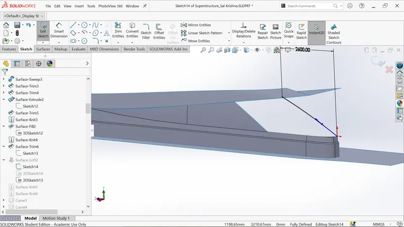
- Create sketch on midplane and convert the selected edges as shown.
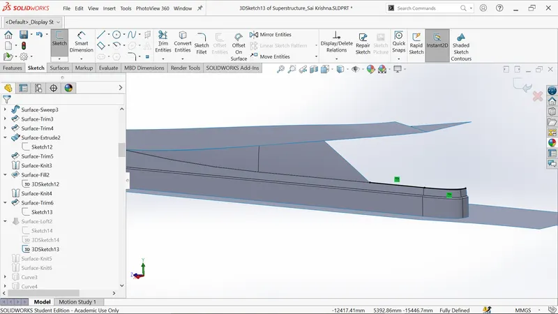
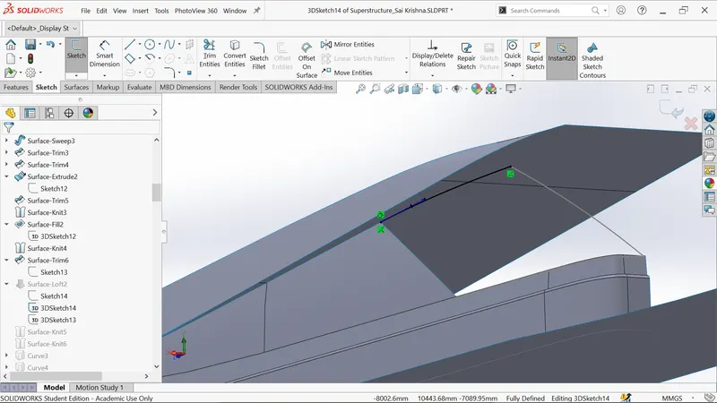
- Create 3D sketch and draw the spline as shown.
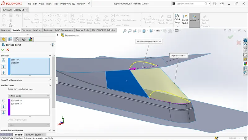
- Generate the lofted surface as shown below.
- Knit the blue surfaces.
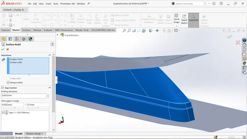
- Knit the blue surfaces.
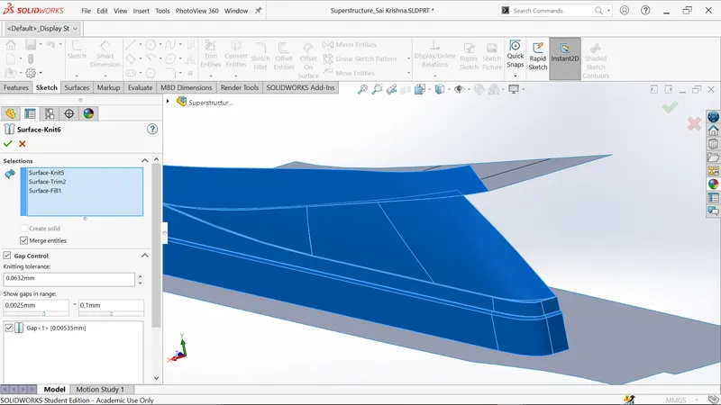
- Create sketch on midplane and draw the spline of exactly matches with blueprint.
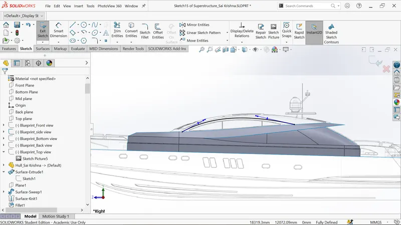
- Sketch on top plane and convert the selected edges as shown.
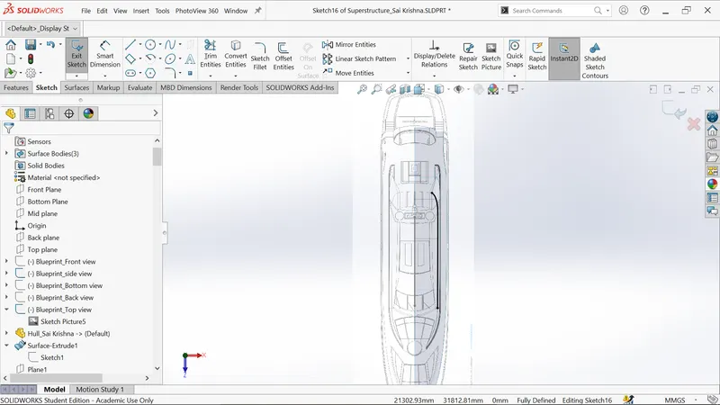
- Project the sketch 15 and sketch16 by using project curve feature.
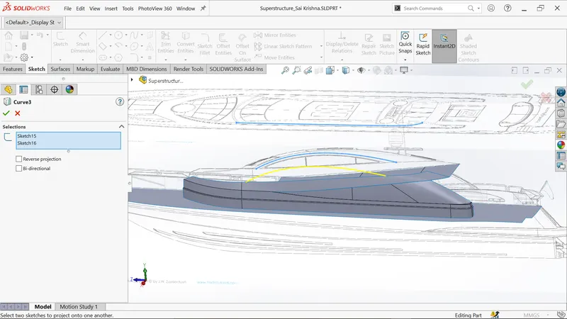
- Create sketch on midplane and draw the spline of exactly matches with blueprint.
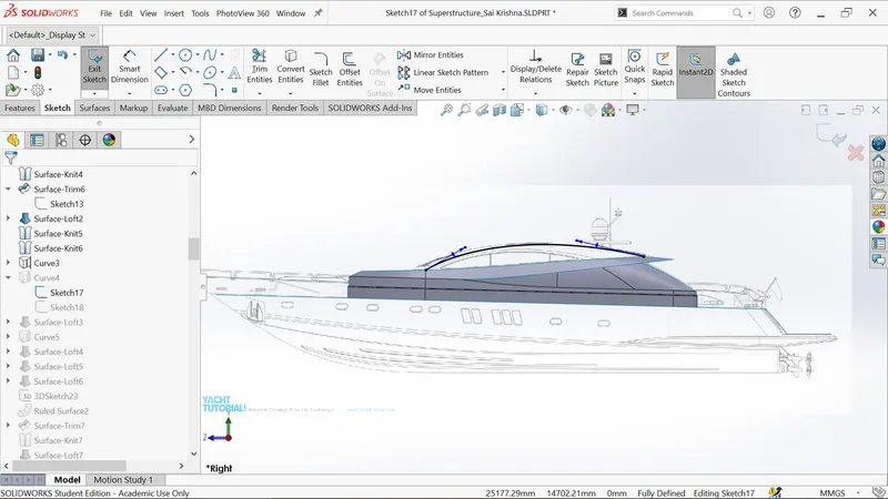
- Sketch on top plane and draw centerline, spline as matching with blueprint.
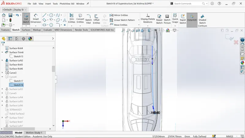
- Project the sketch 17 and sketch18 by using project curve feature.
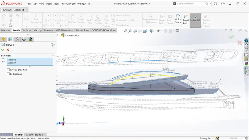
- Select 3D sketch and convert the edge and right click on spline and create extra point using sketch entities.
- Make coincident the point with spline and trim the extra line as shown below.
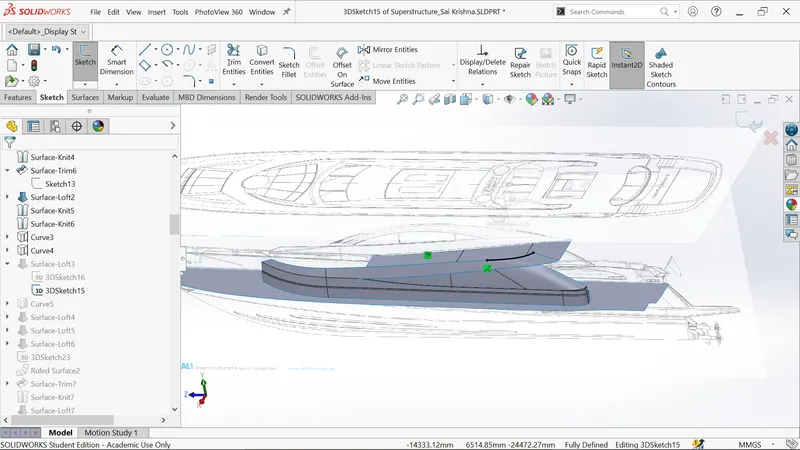
- Create 3D sketch and draw the spline as shown.
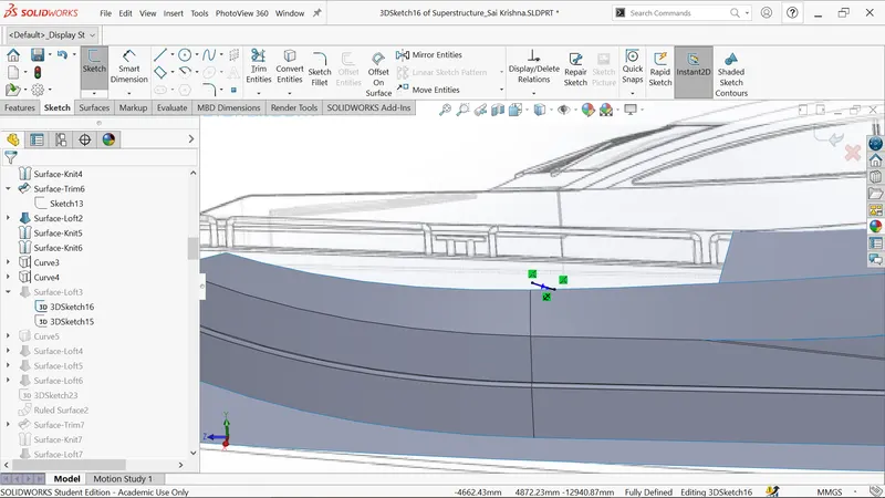
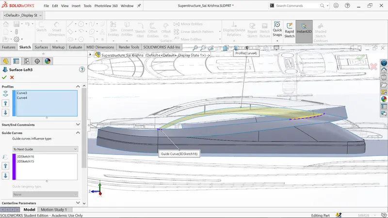
- Generate the lofted surface as shown below.
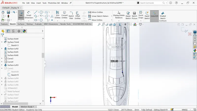
- Sketch on top plane and convert the edge and draw the spline as shown.
- Create sketch on midplane and draw the spline of exactly matches with blueprint.
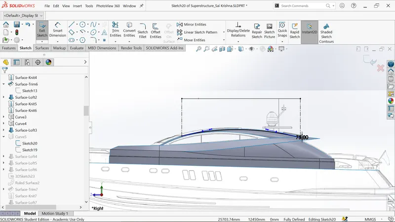
- Project the sketch 19 and sketch20 by using project curve feature.
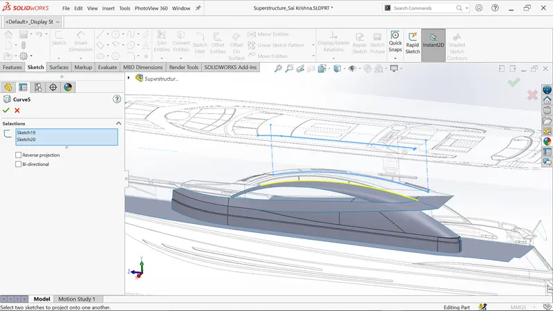
- Create 3D sketch and draw the line connect endpoint of curve5 and surface loft3.
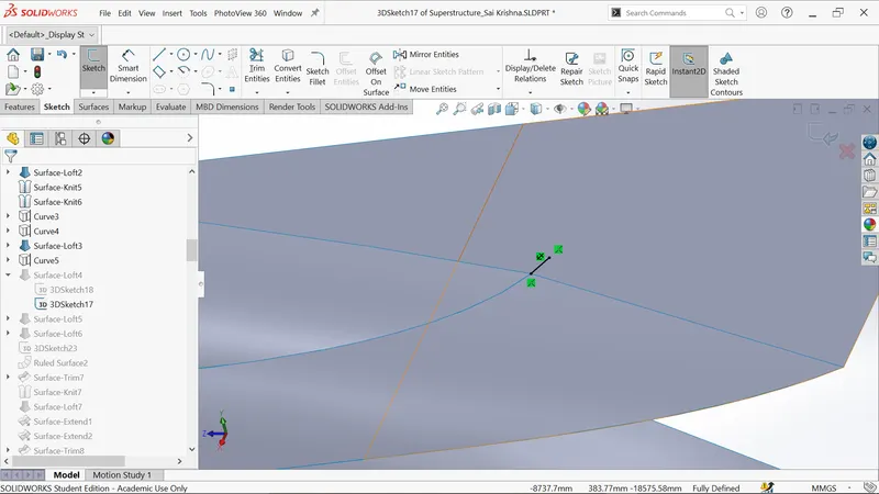
- Select 3D sketch and convert the edge and right click on spline and create extra point using sketch entities.
- Make coincident the point with spline and trim the extra line as shown below.
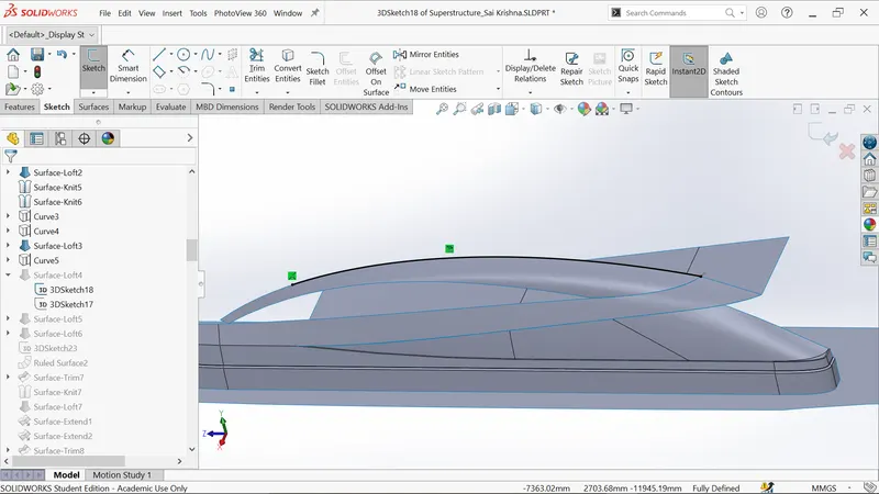
- Generate the lofted surface as shown below.
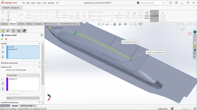
- Create sketch on midplane and draw the spline of exactly matches with blueprint.
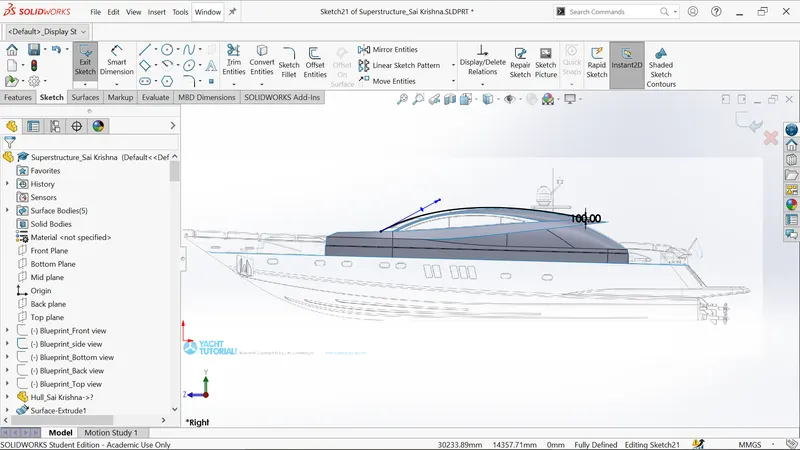
- Create the 3D sketch 19 and draw spline as shown below.
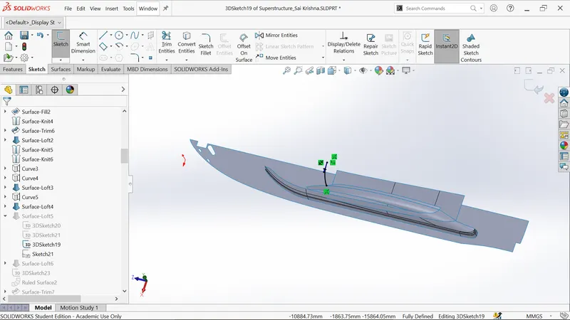
- Create the 3D sketch 20 and draw spline as shown below.
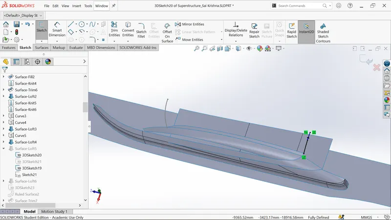
- Create the 3D sketch21 and draw spline as shown below.
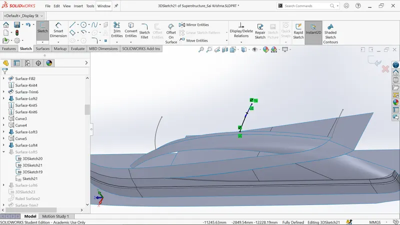
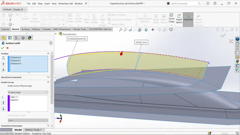
- Generate the lofted surface as shown below.
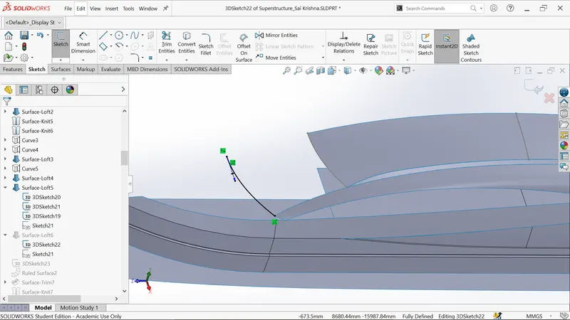
- Create the 3D sketch22 and draw spline as shown below.
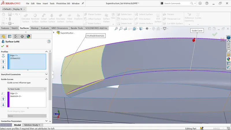
- Generate the lofted surface as shown below.
- Select 3D sketch and convert the edges as shown.
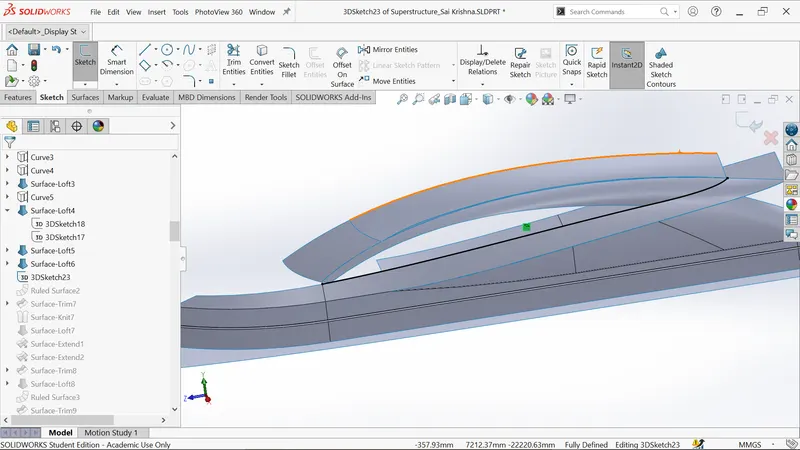
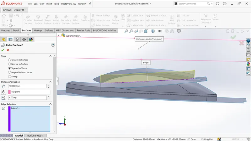
- Generate the ruled surface of selected edge as shown.
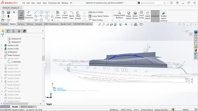
- Create sketch on midplane and draw the spline of exactly matches with blueprint.
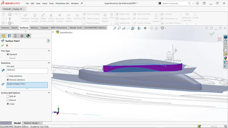
- Trim the purple surface by selecting sketch22 as trim tool.
- Knit the blue surfaces.
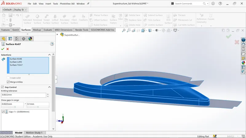
- Generate the lofted surface as shown below.
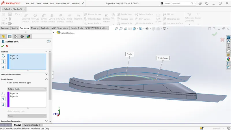
- Extend the surface of selected edge of distance 500 mm.
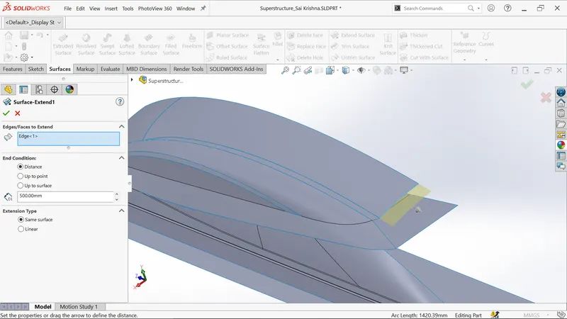
- Extend the surface of selected edge of distance 500 mm.
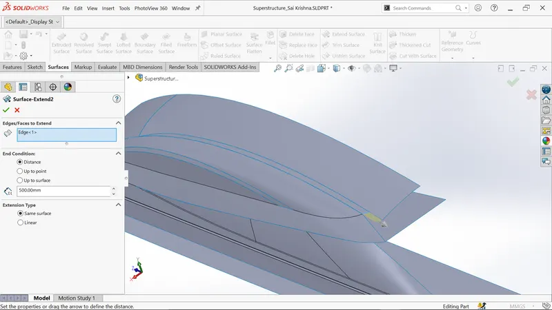
- Create sketch on top plane and draw the spline of exactly matches with blueprint.
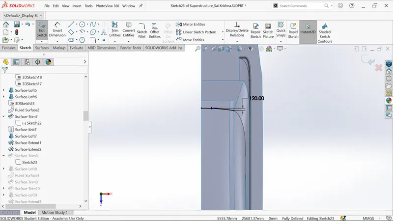
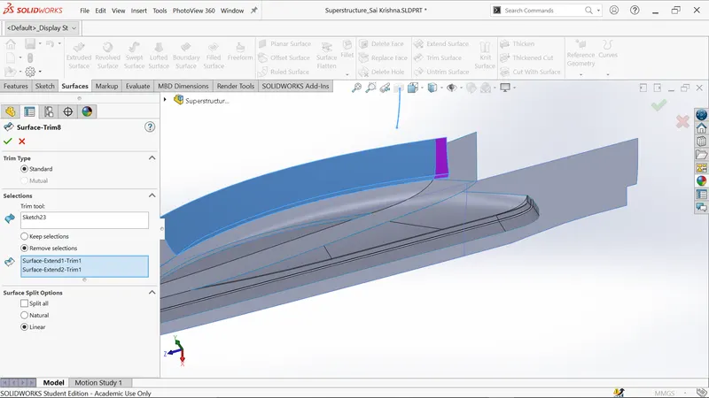
- Trim the purple surface by selecting sketch23 as trim tool.
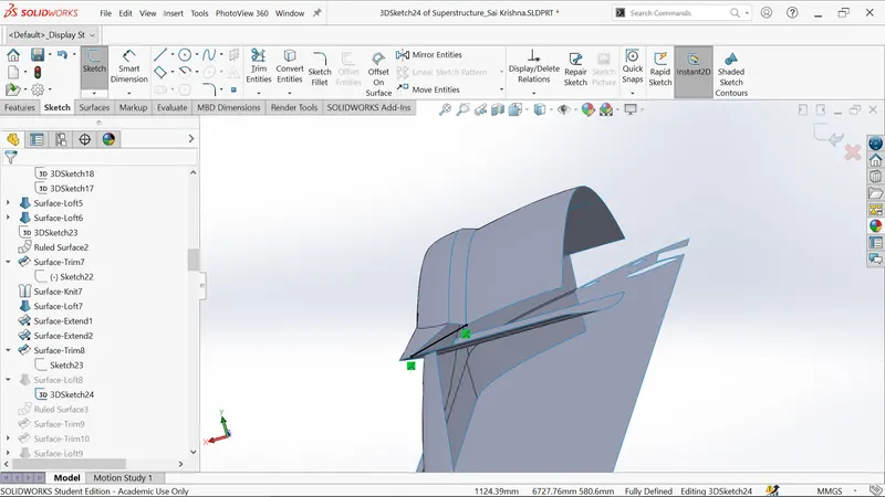
- Select 3D sketch and draw straight line as shown below.
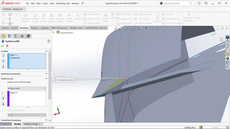
- Generate the lofted surface as shown below.
- Generate the ruled surface for selected edge.
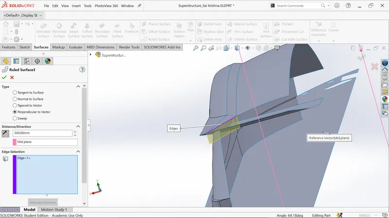
- Trim the purple surface by selecting surface trim5 as trim tool.
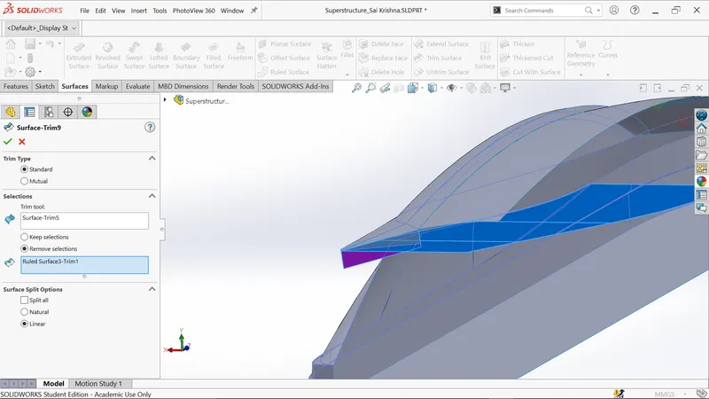
- Create sketch on top plane and convert the edge.
- Draw the spline and connect with convert edge as shown.
- Trim the extra lines.
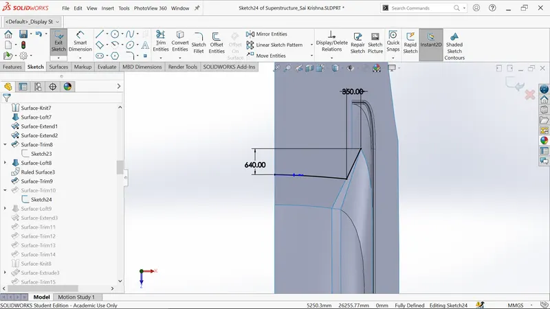
- Trim the purple surface by selecting sketch24 as trim tool.
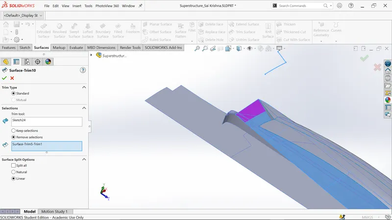
- Sketch on midplane and draw spline of connecting with two end points as shown.
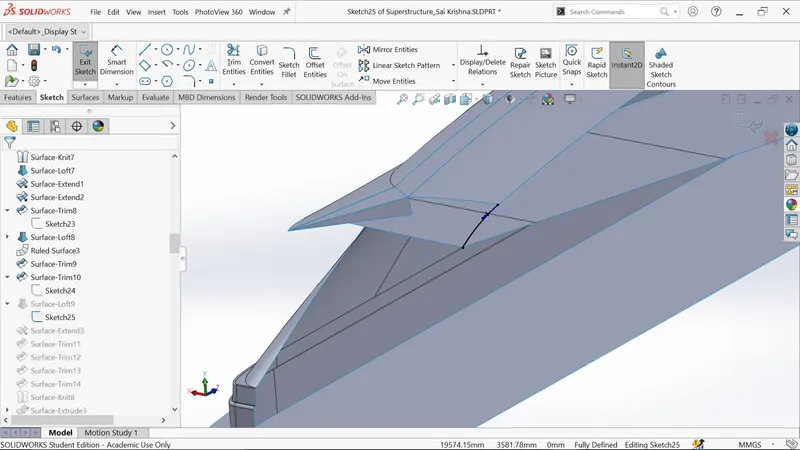
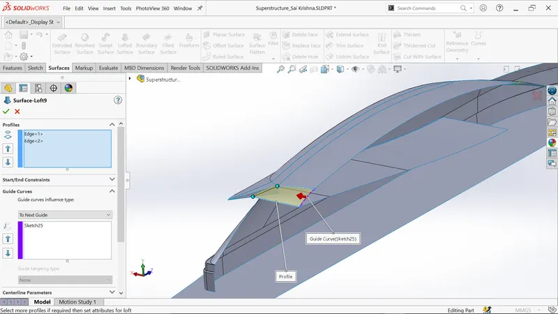
- Generate the lofted surface as shown below.
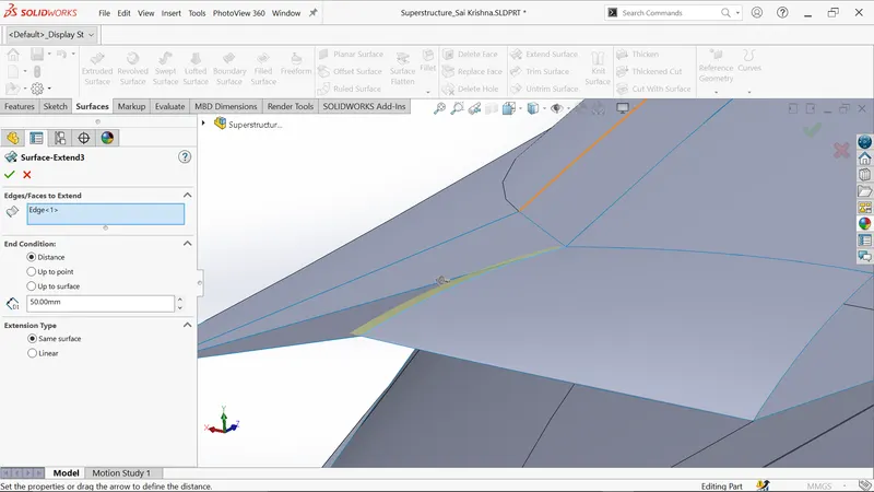
- Extend the surface of selected edge of distance 50 mm.
- Trim the surfaces as shown.
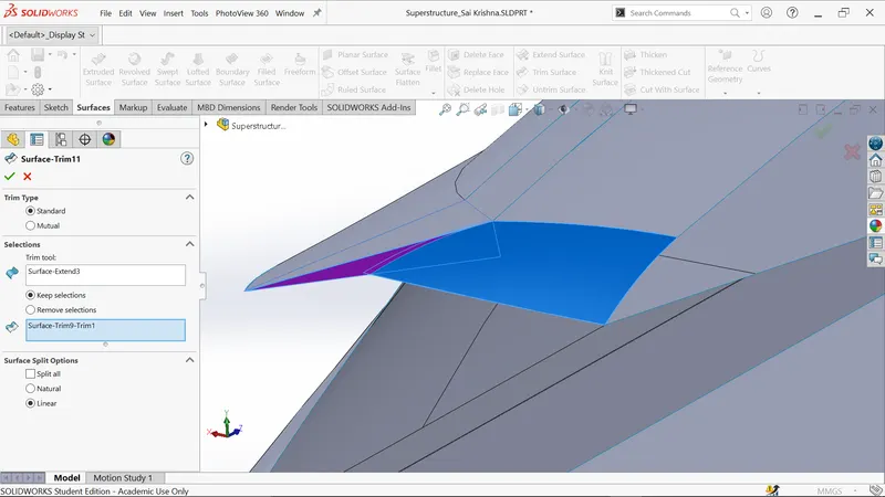
- Trim the surfaces as shown.
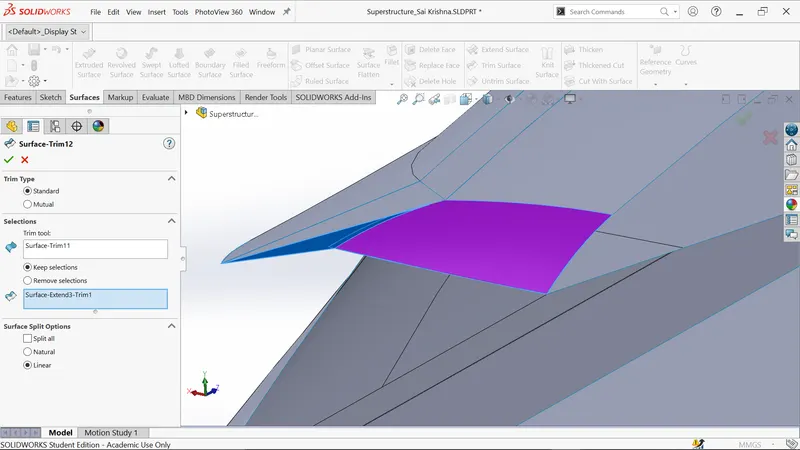
- Trim the surfaces as shown.
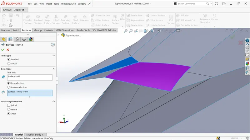
- Trim the surfaces as shown.
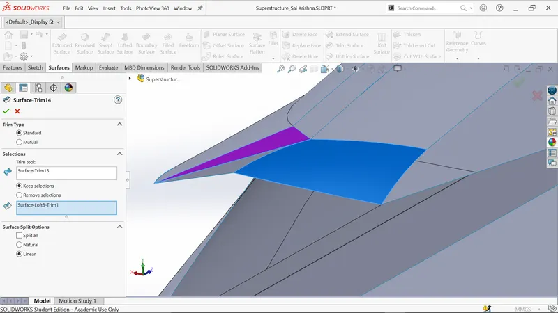
- Knit all the blue surfaces.
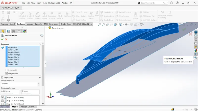
- Create sketch on deck surface and draw straight line.
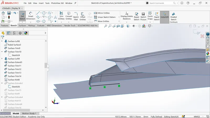
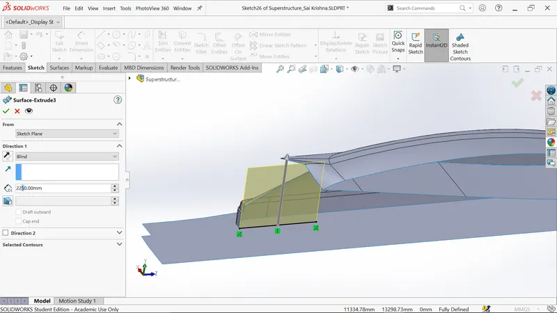
- Extrude the sketch26 of depth 2250mm.
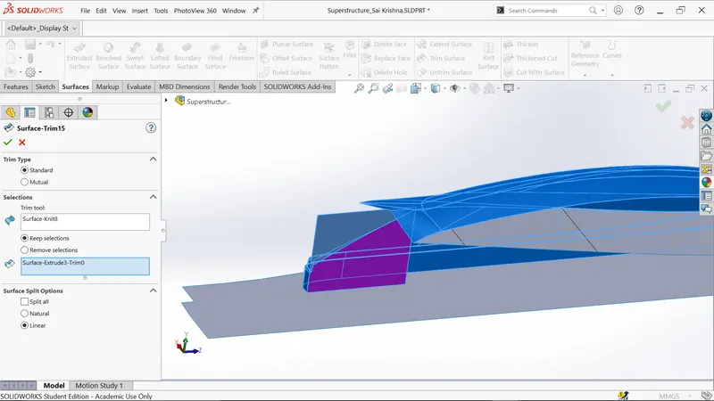
- Trim the surfaces as shown.
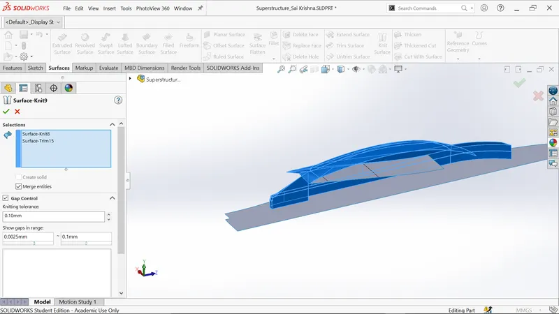
- Knit all the blue surfaces.
- Create sketch on deck surface and draw spline as shown.
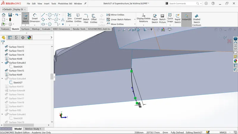
- Extrude the sketch27 upto pink surface.
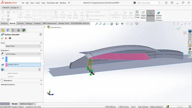
- Knit all the blue surfaces.
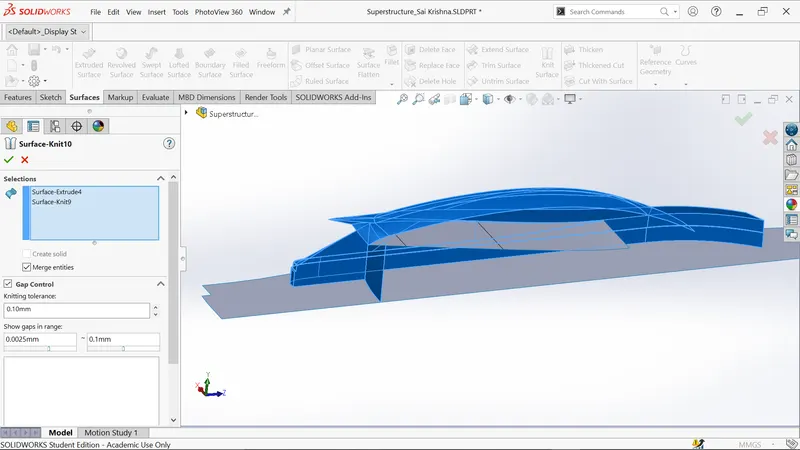
- Extend the four edges as shown below.
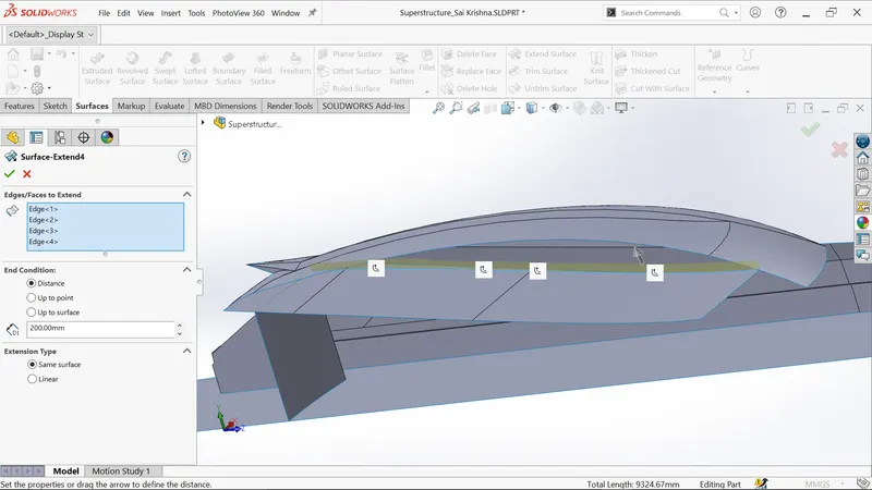
- Trim the surfaces as shown.
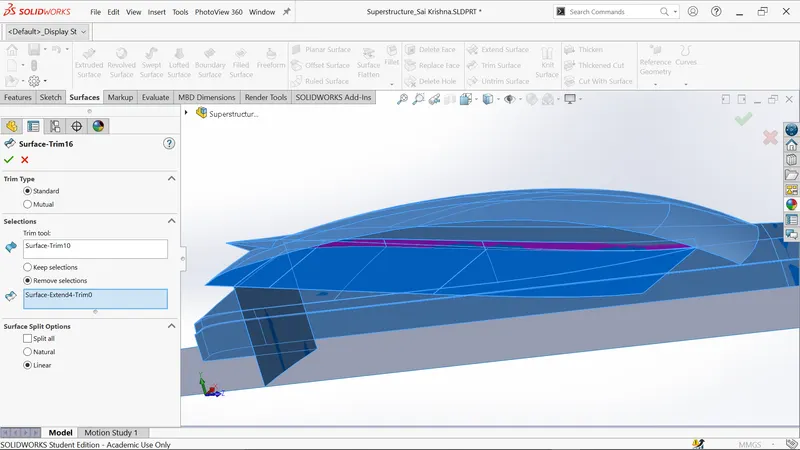
- Trim the surfaces as shown.
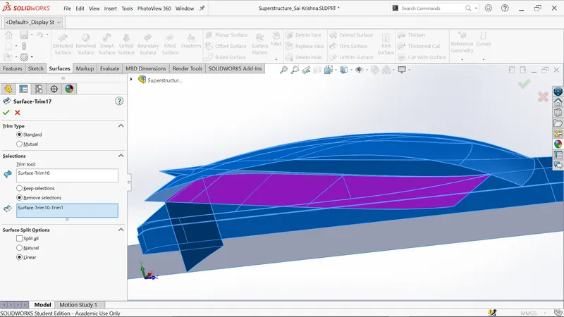
- Trim the surfaces as shown.
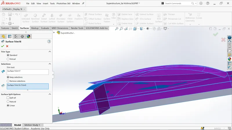
- Knit all the blue surfaces.
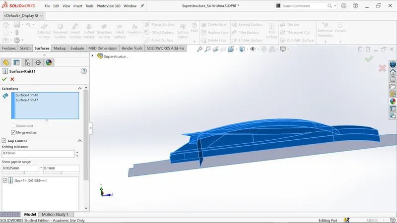
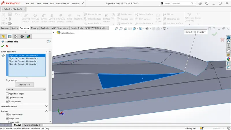
- Fill the surfaces by selecting the four edges in order to remove the gap as shown.
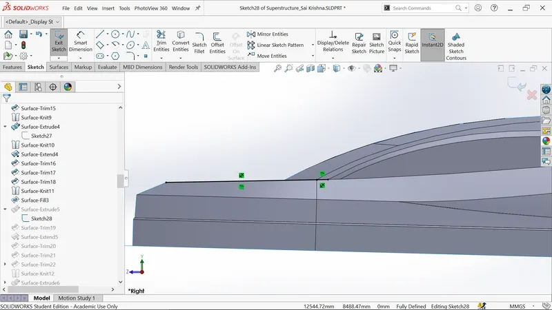
- Sketch on midplane and convert the two edges.
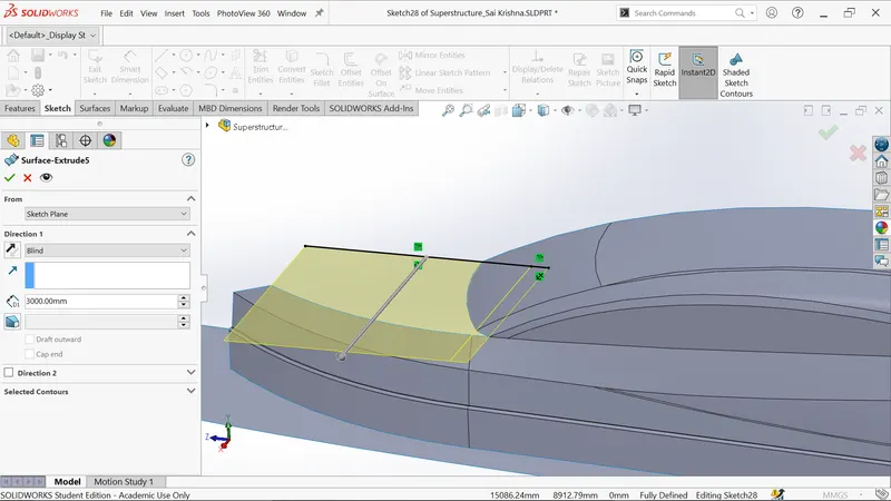
- Extrude sketch28 of depth 3000mm
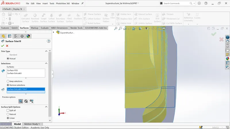
- Trim the surfaces as shown.
- Extend the two selected edges.
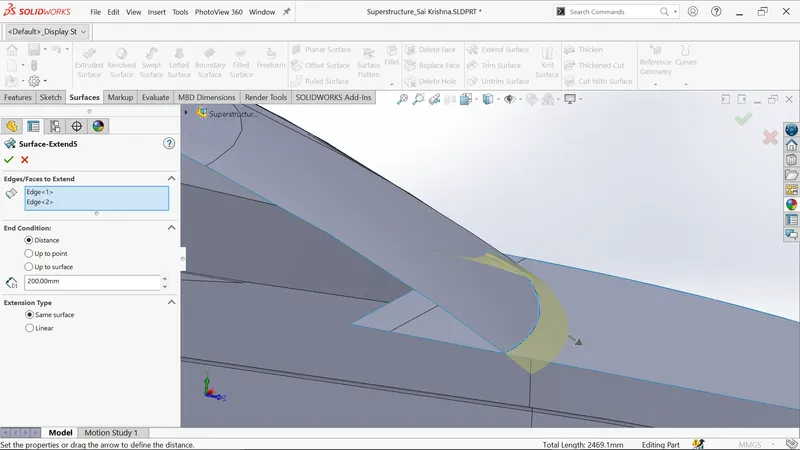
- Trim the purple surface as shown.
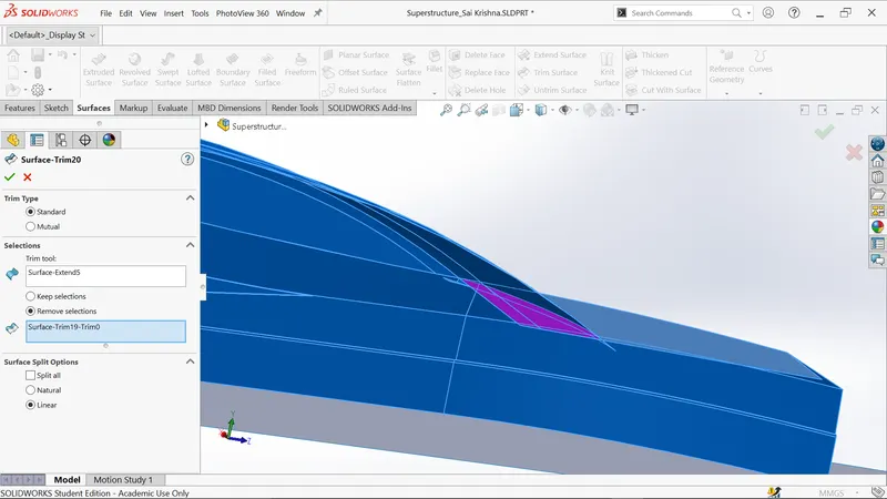
- Trim the purple surface as shown.
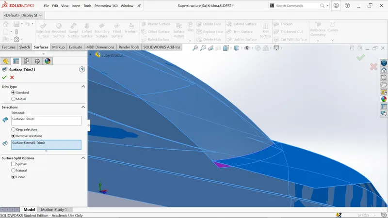
- Sketch on top plane and draw two splines as per demensions.
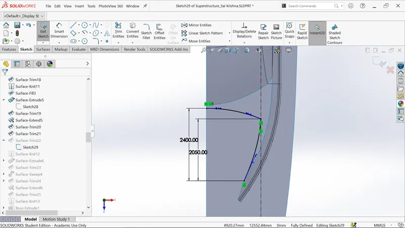
- Trim the purple surface by selecting sketch 29 as trim tool.
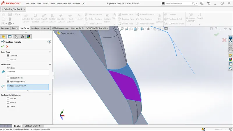
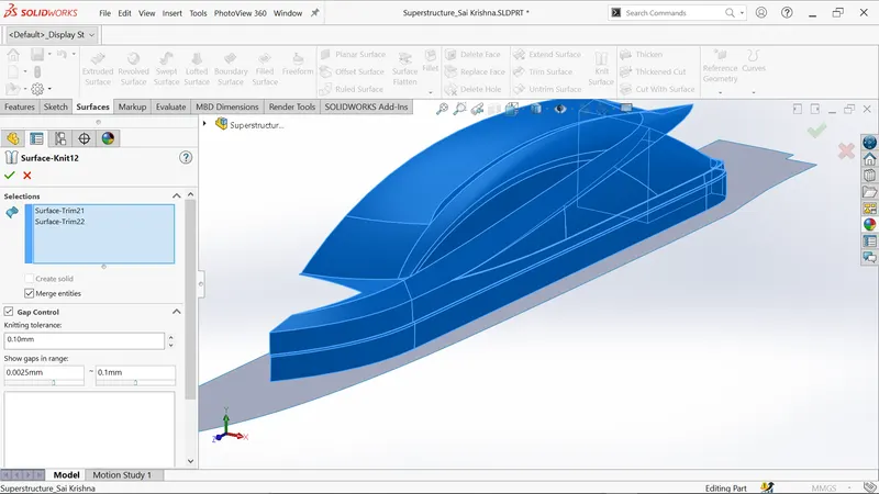
- Knit all the blue surfaces.
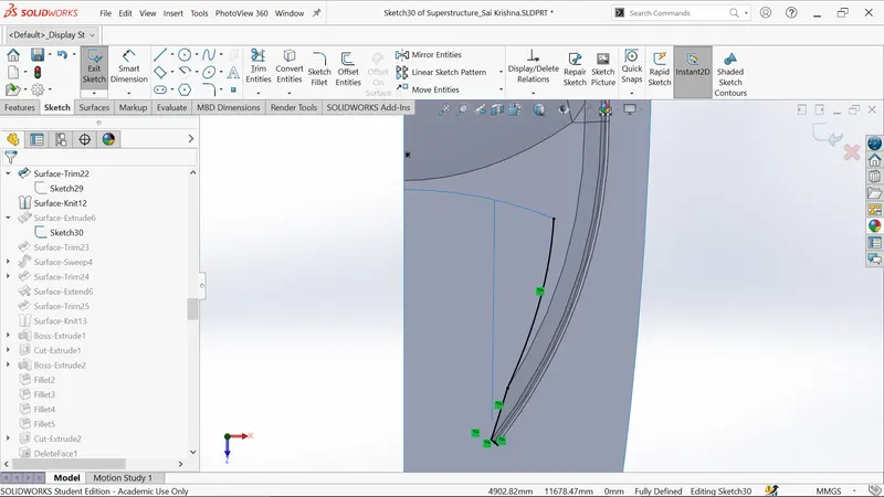
- Sketch on deck surface and convert the selected edges.
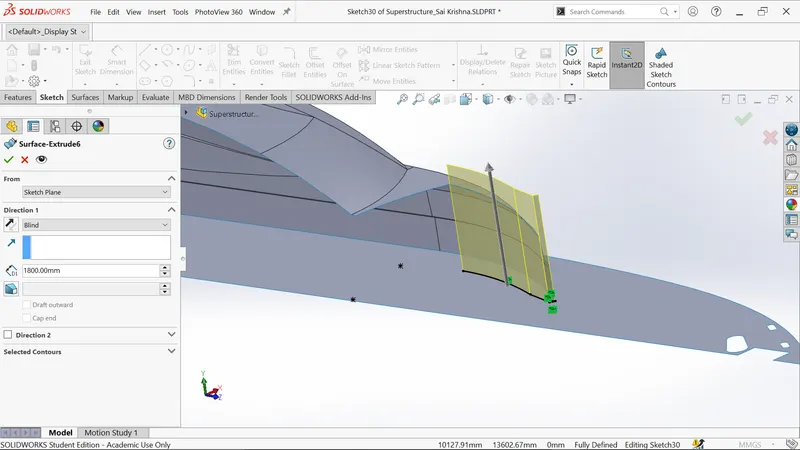
- Extrude sketch30 of depth 1800mm.
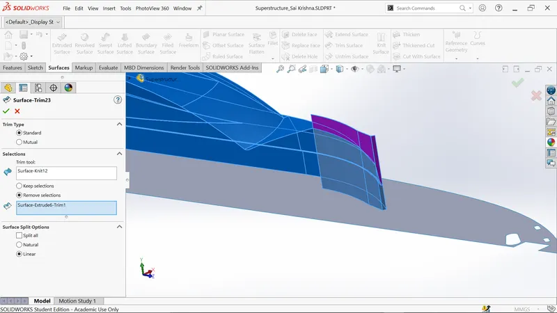
- Trim the purple surface as shown.
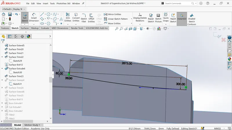
- Create new sketch on midplane and draw the line, spline as per dimension as shown.
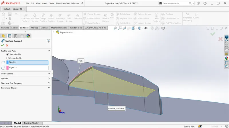
- Generate the surface sweep as shown below.
- Sketch on top plane and draw the straight line.
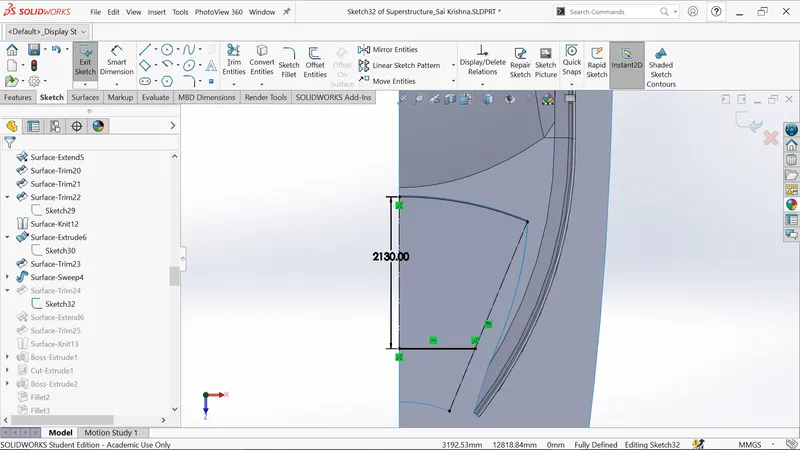
- Trim the purple surface by selecting sketch 32 as trim tool.
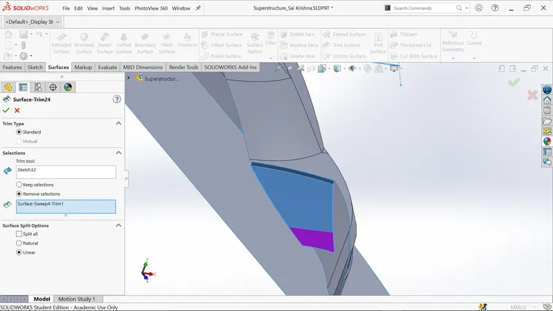
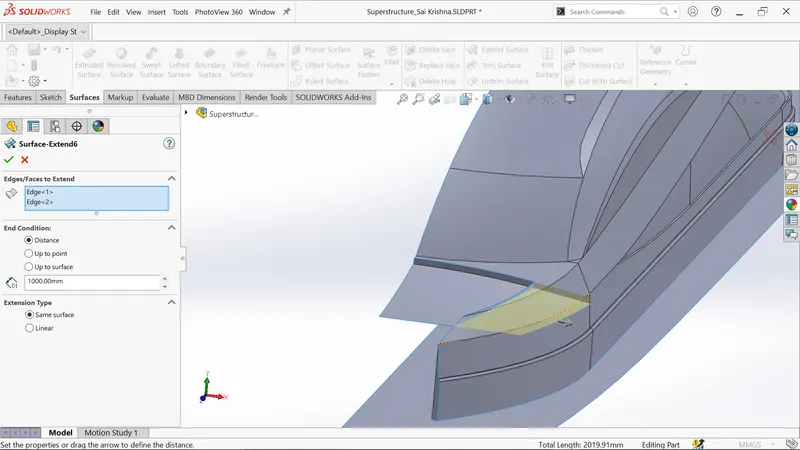
- Extend the two selected edges.
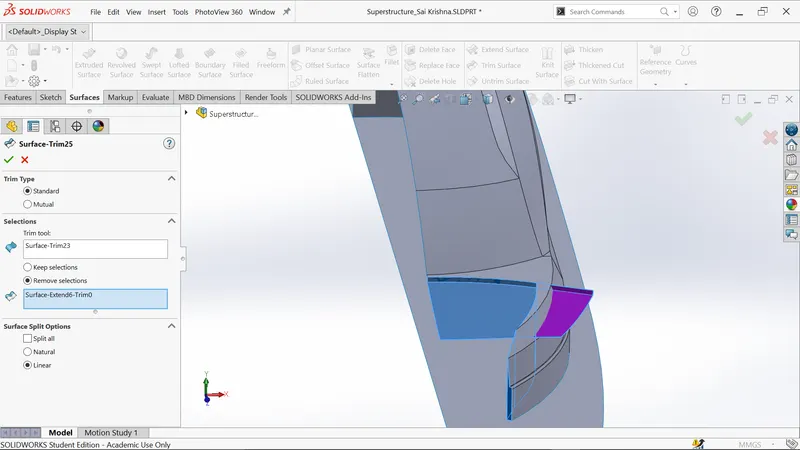
- Trim the purple surface as shown below.
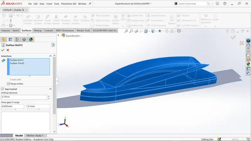
- Knit all the blue surfaces.
- Sketch on deck surface and draw the circle with diameter 1460 mm.
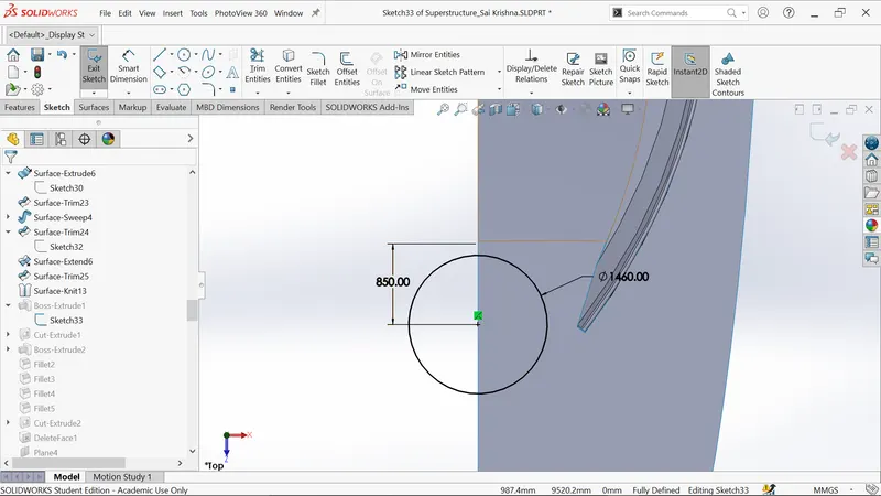
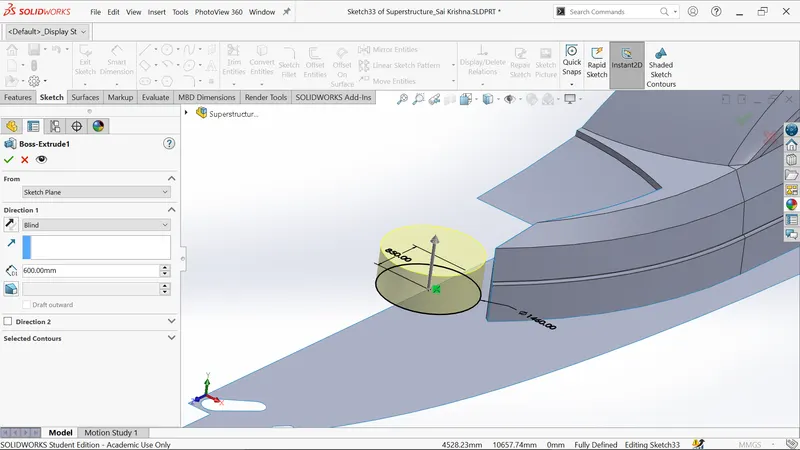
- Extrude the sketch33 of depth 600 mm.
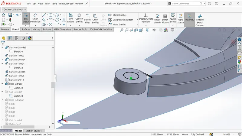
- Sketch on above extrude surface and draw the circle with diameter 700 mm.
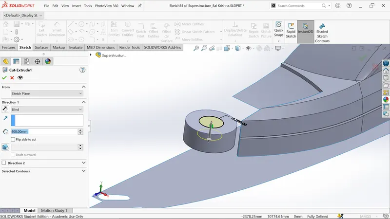
- Perform extrude cut for sketch34 of depth 400 mm.
- Sketch on above extrude surface and draw the two circles as shown below.
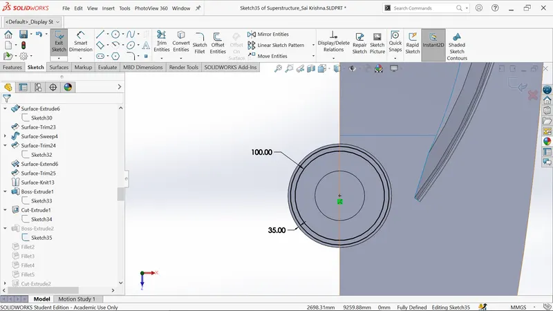
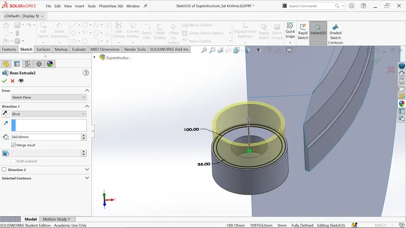
- Extrude the sketch35 of depth 560mm.
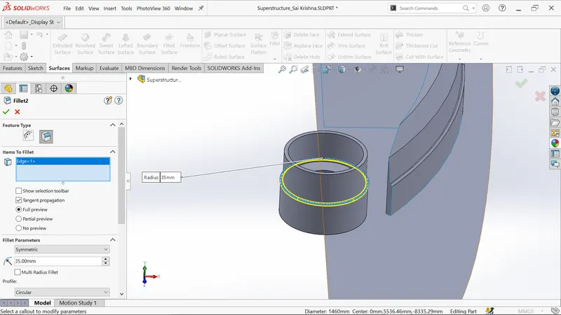
- Apply the fillet on the blue edge.
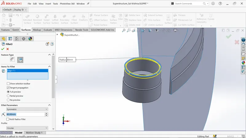
- Apply the fillet on the blue edge.
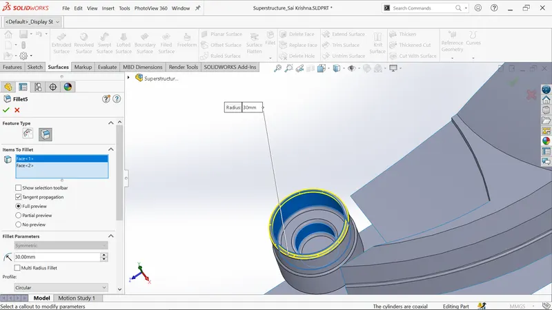
- Apply the fillet on two faces as shown.
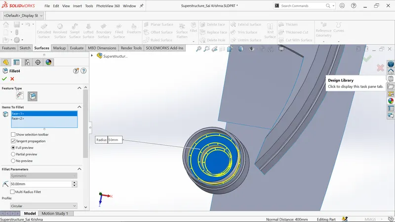
- Apply the fillet on two faces as shown.
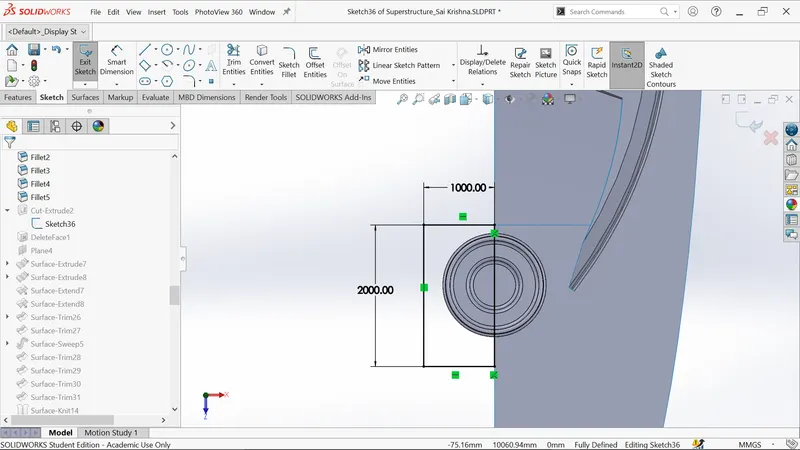
- Sketch on deck surface and draw a rectangle as per dimensions.
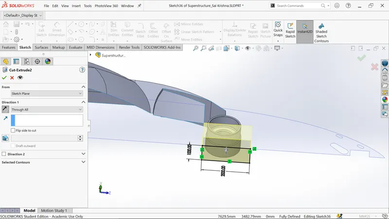
- Perform extrude cut for sketch36 through all directions.
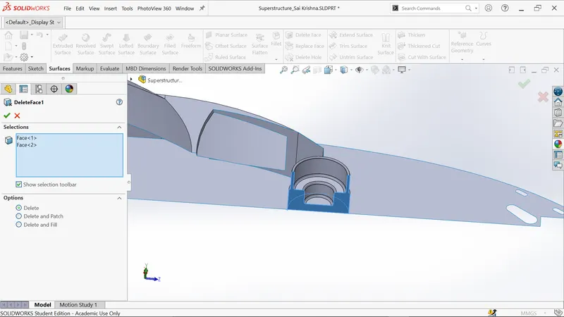
- Delete the selected face.
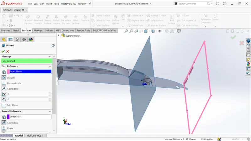
- Create the new plane as shown below.
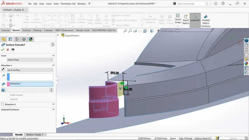
- Sketch on new plane and draw the lines as shown.

- Generate surface extrude for sketch37 upto pink surface.
- Sketch on above extrude surface and draw the lines as shown below.
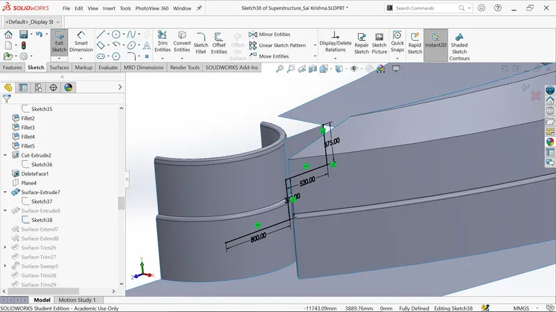
- Generate surface extrude for sketch38 of depth 1000mm.
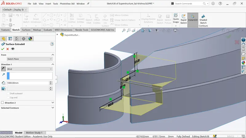
- Extend the two selected edge of distance 550 mm.
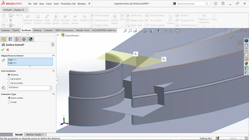
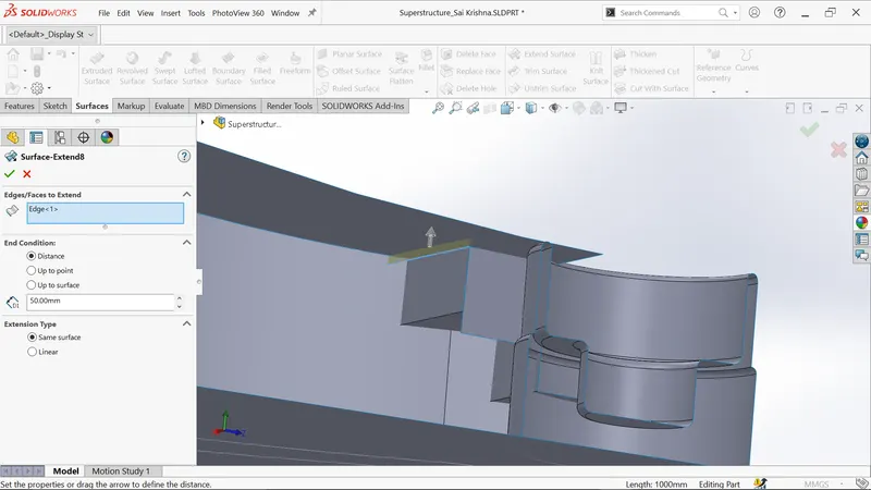
- Extend the selected edge of distance 50 mm.
- Craete sketch on surface extrude8 and draw the spline as shown below.
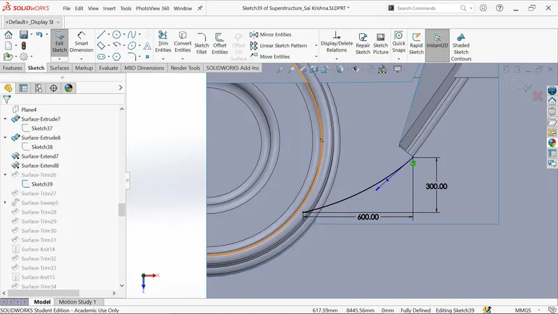
- Trim purple surface by selecting sketch39 as trim tool.
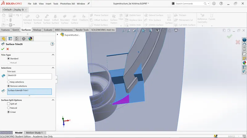
- Trim purple surface as shown below.
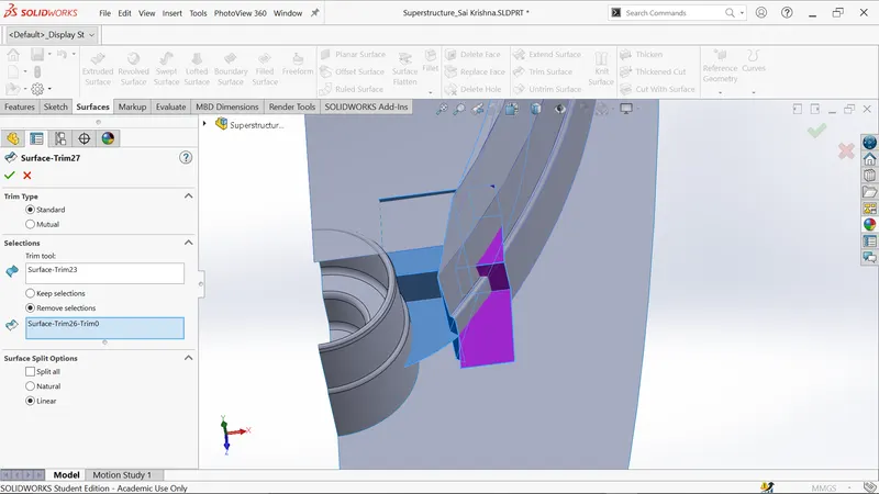
- Select 3D sketch and convert the selected edge.
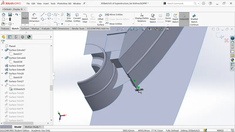
- Generate the sweep as shown below.
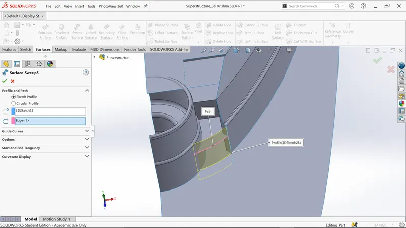
- Trim the purple surface as shown below.
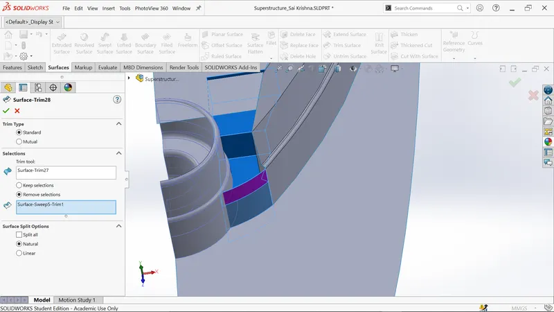
- Trim purple surface by selecting hull surface as trim tool.
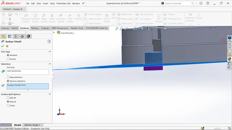
- Trim the surface as shown below.
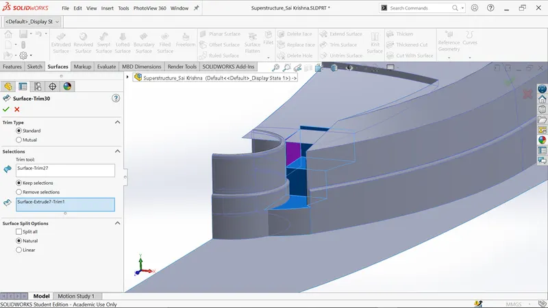
- Trim the surfaces as shown below.
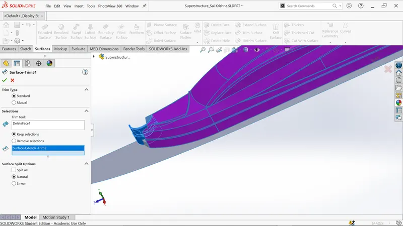
- Knit the blue surfaces.
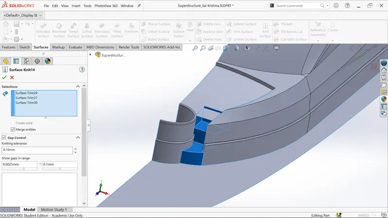
- Trim the purple surface as shown below.
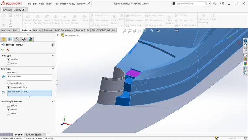
- Trim the purple surface as shown below.
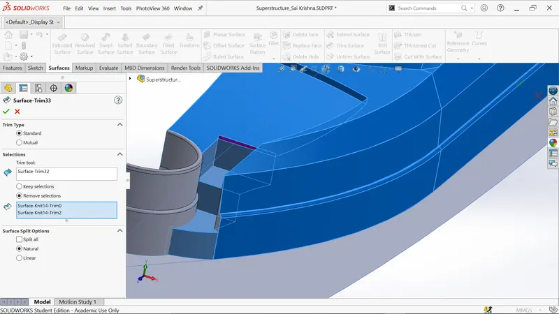
- Knit all the blue surfaces.
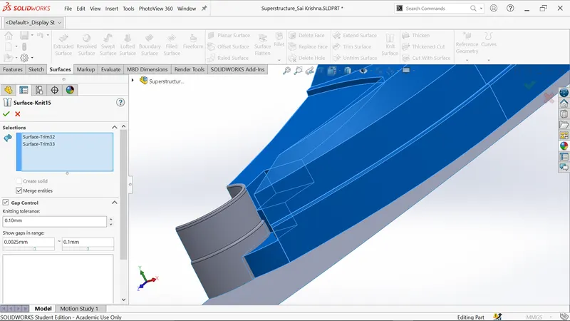
- Trim the purple surface as shown below.
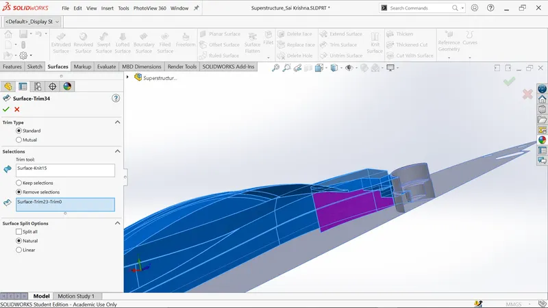
- Knit all the blue surfaces.
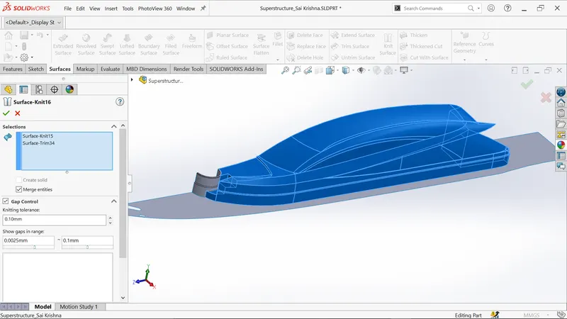
- Knit all the blue surfaces.
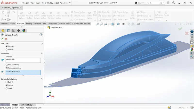
- Trim the purple surface as shown below.
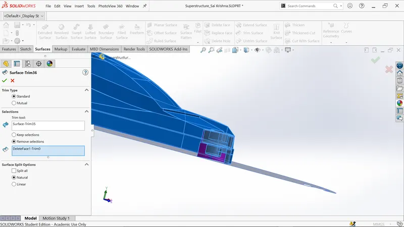
- Knit all the blue surfaces.
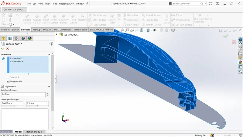
- Trim the purple hull surface as shown below.
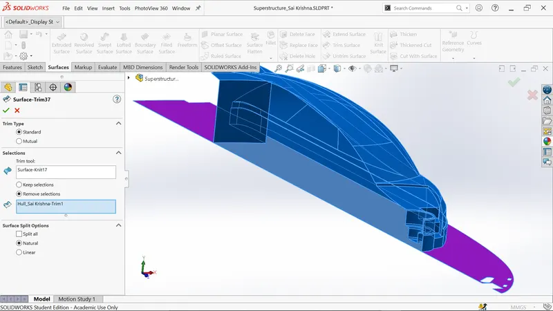
- Knit all the blue surfaces.
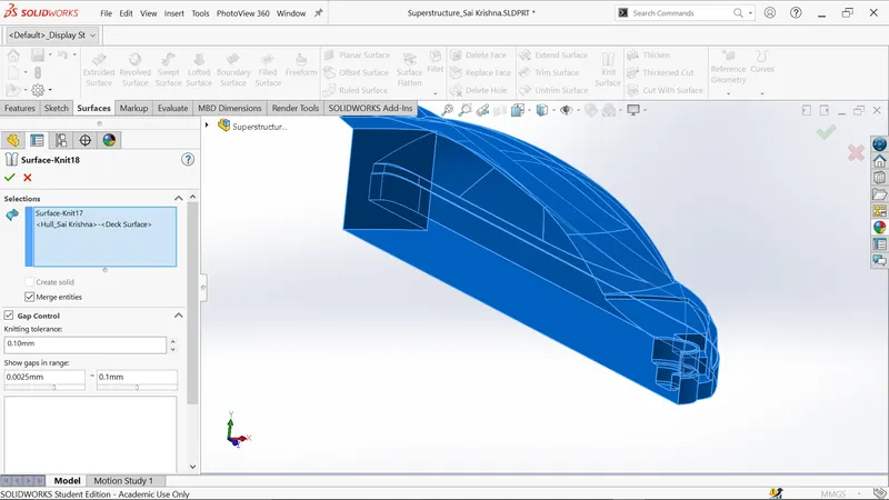
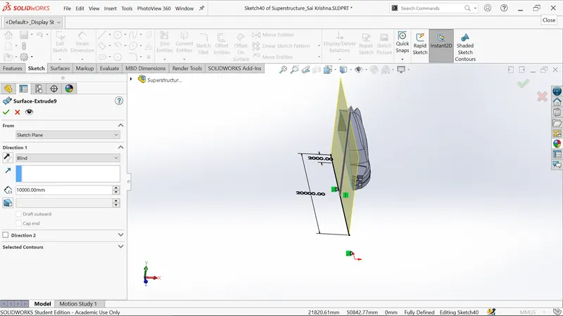
- Sketch on bottom plane and draw horizontal line as shown below.
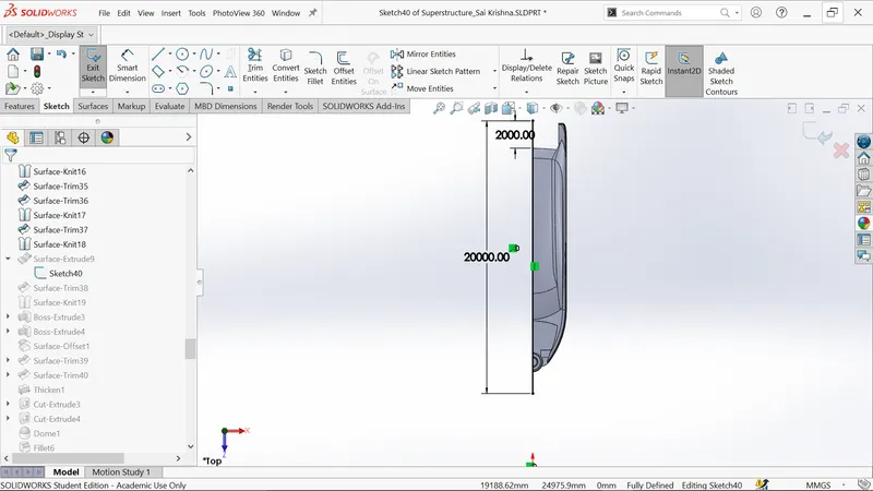
- Generate surface extrude of depth 10000mm.
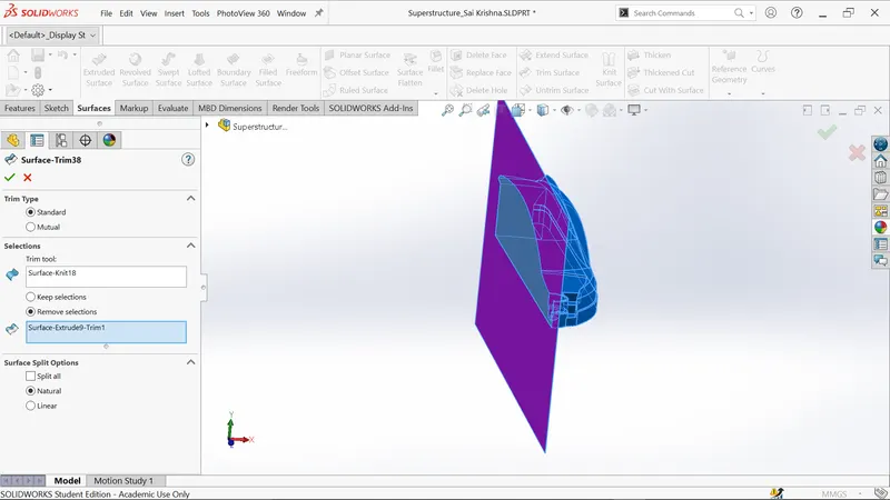
- Trim the selected purple surface area.
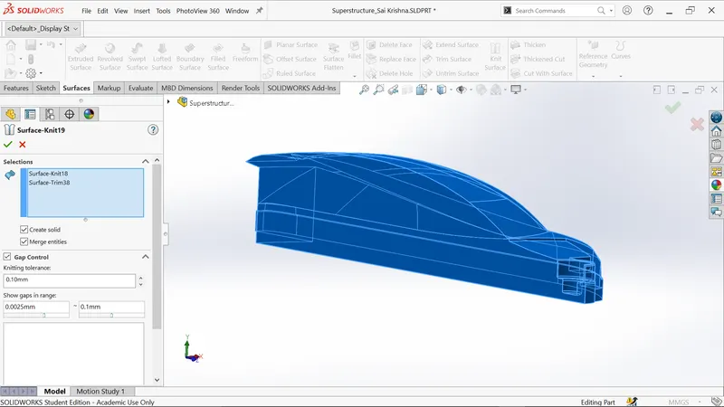
- Knit the two blue surfaces.
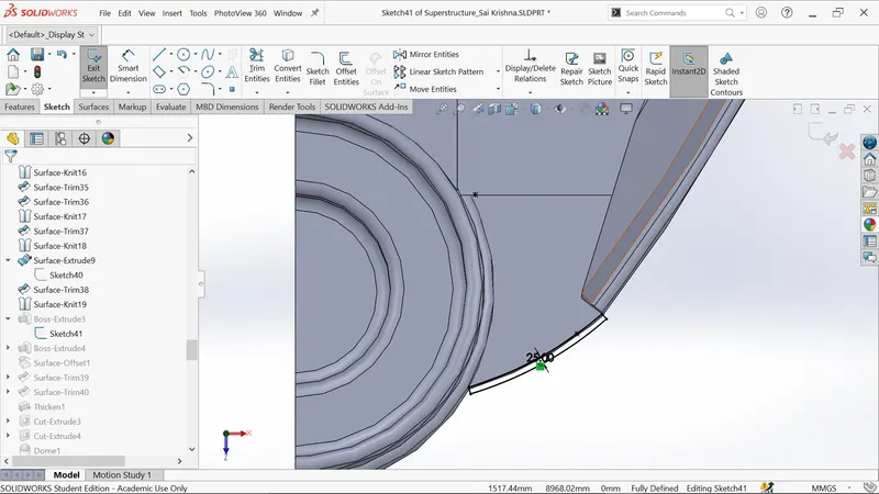
- Sketch on the surface as shown and convert the edge.
- Offset the edge of distance 25mm.
- Connect the two edges with line to form closed contour.
- Generate the extrude of depth 40 mm.
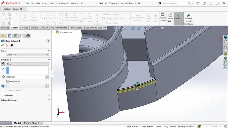
- Sketch on the surface as shown and convert the edge.
- Offset the edge of distance 25mm.
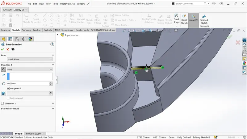
- Convert the two side edges and trim extra lines to form closed contour.
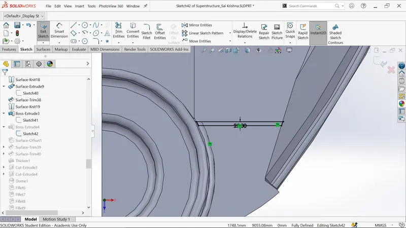
- Generate the extrude of depth 40 mm.
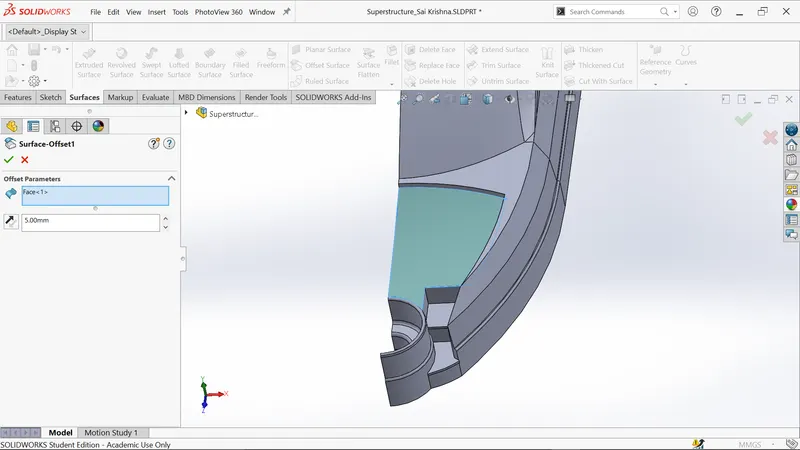
- Offset the surface of distance 5mm.
- Sketch on top plane and draw the line as shown.
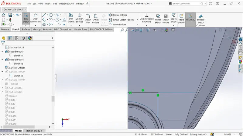
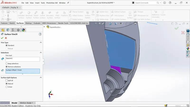
- Trim the purple surface by selecting sketch43 as trim tool.
- Sketch on top plane and offset the surface of distance 5mm.
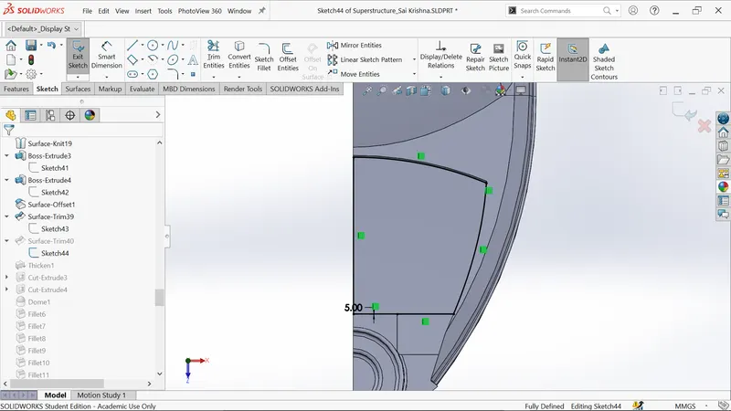
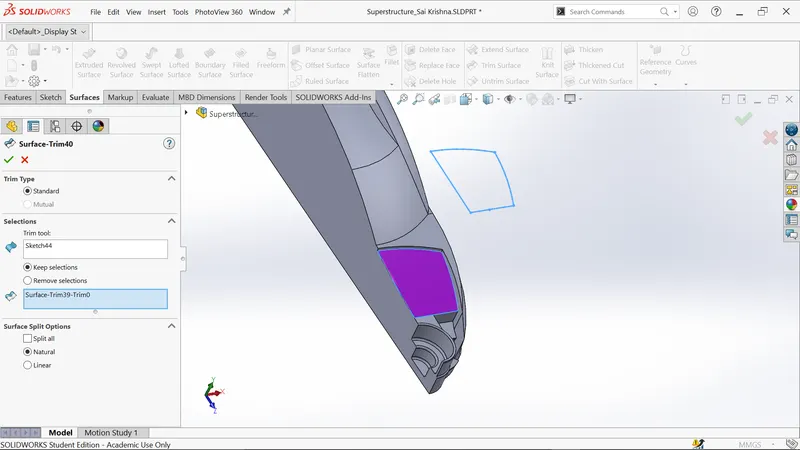
- Trim the purple surface by selecting sketch44 as trim tool.
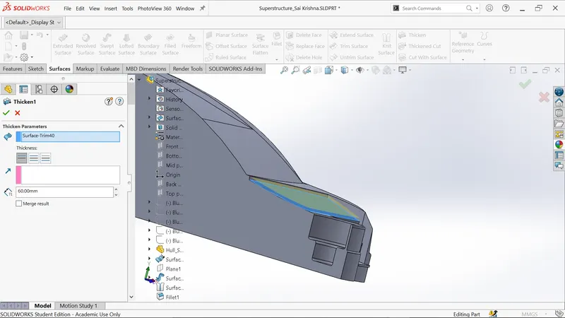
- Thicken the surface with thickness 60 mm.
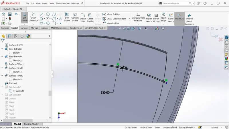
- Offset the edge of distance 530mm.
- Offset the previous edge of distance 20mm apart..
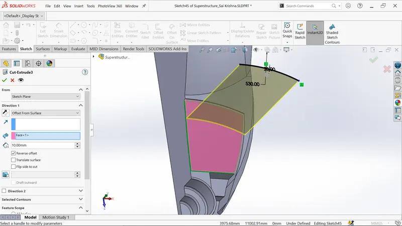
- Generate the cut extrude offset from pink surface.
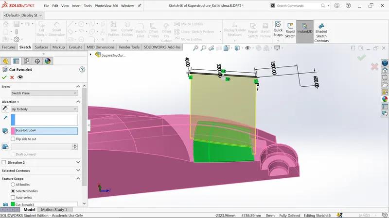
- Sketch on top plane and draw the rectangle as per dimensions.
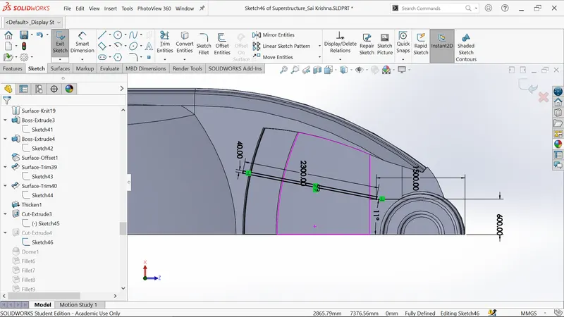
- Generate the cut extrude upto pink body.
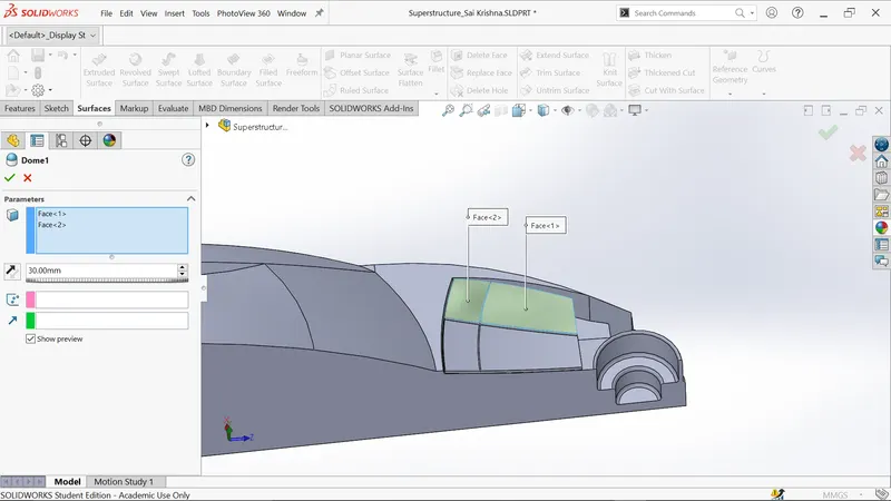
- Apply the dome feature on two surfaces.
- Add the fillet as shown.
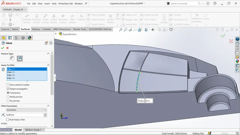
- Similarly apply the fillet for all sharp edges of the seat.
- Create the new plane as shown below.
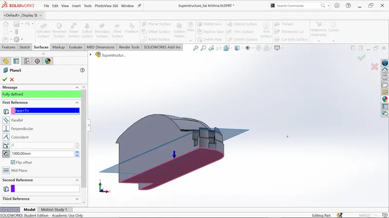
- Sketch on plane5 and draw the half circle,centerline and trim the uncessary lines .
- Draw 3-point arc as shown below and complete the profile.
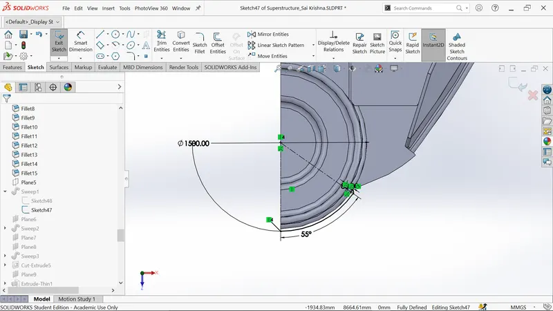
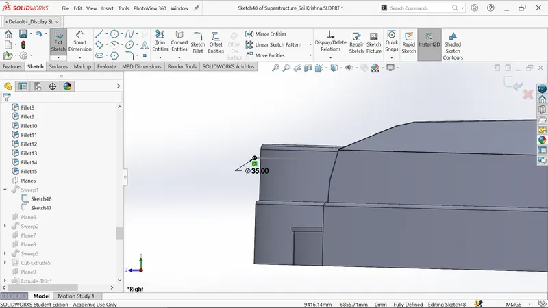
- Sketch on midplane and draw the circle of diameter 35mm.
- Select the pierce of connecting circle with previous sketch.
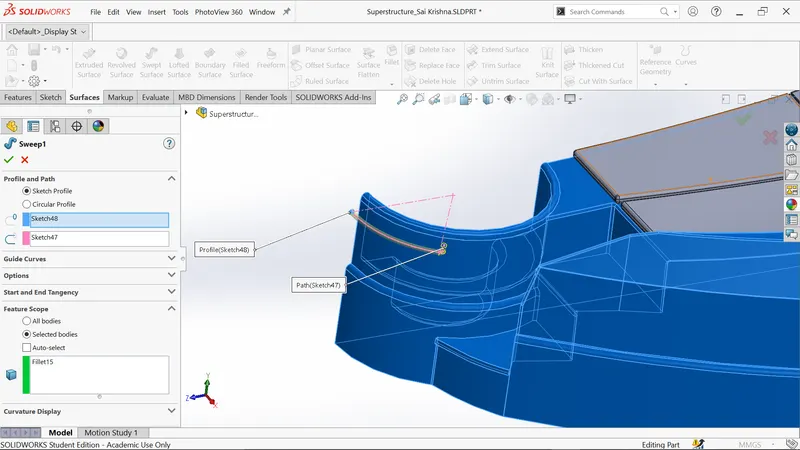
- Generate the sweep using sketch 48 and sketch 47.
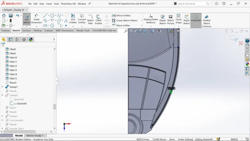
- Sketch on plane5and offset the selected edge of 35mm as shown.
- Draw 3-point arcs at the end of offset lines.
- Create new plane6 as shown below.
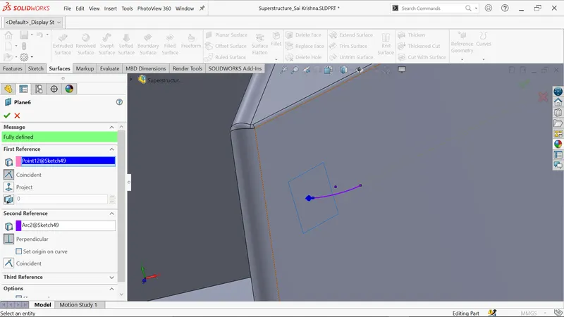
- Sketch on new plane6 and draw the circle of diameter 35mm.
- Select the pierce of connecting circle with previous sketch.
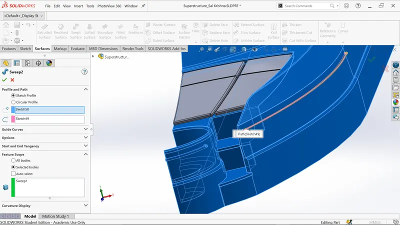
- Generate the sweep using sketch 49 and sketch 50.
- Simialrly generate the sweep on the back side as shown below.
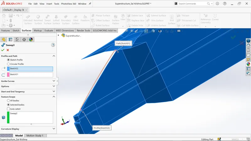
- Sketch on backplane and complete profile as shown below.
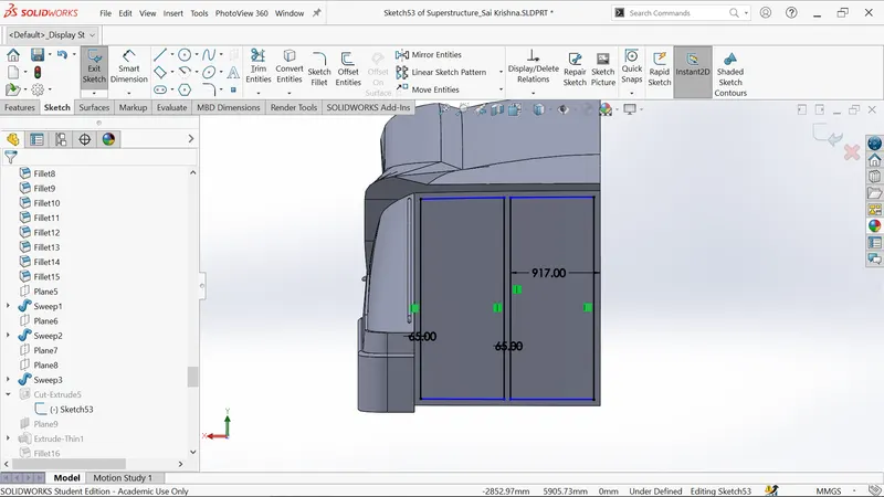
- Generate the cut extrude inwards with depth 25 mm.
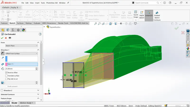
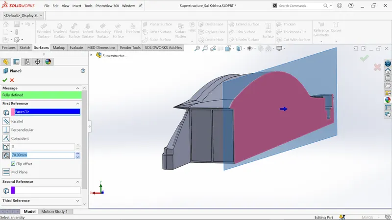
- Create the new plane9 as shown below.
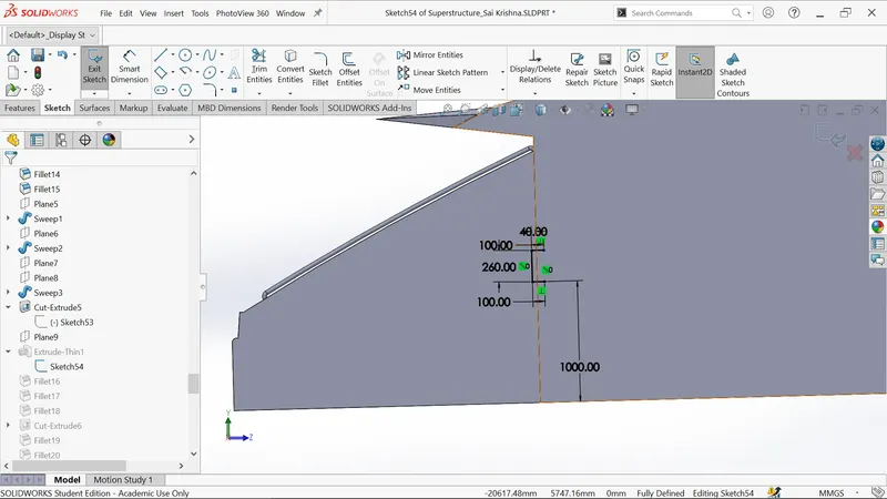
- Sketch on new plane and three lines as shown below.
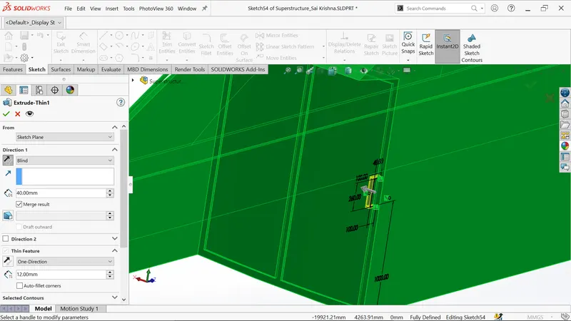
- Generate the thin extrude outwards with depth 40 mm.
- Apply the fillet for the following edges.
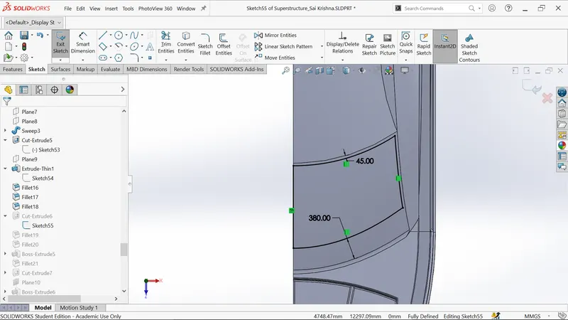
- Create a sketch on top plane and offset the edges as per dimensions as shown below.
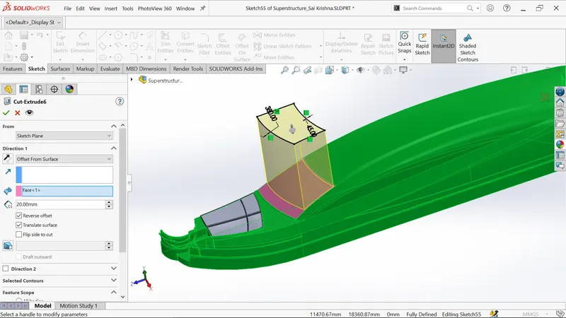
- Generate the cut extrude is offset from surface of 20 mm inwards.
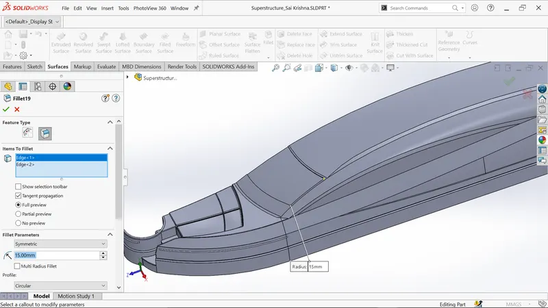
- Apply the fillet for two edges of 15mm.
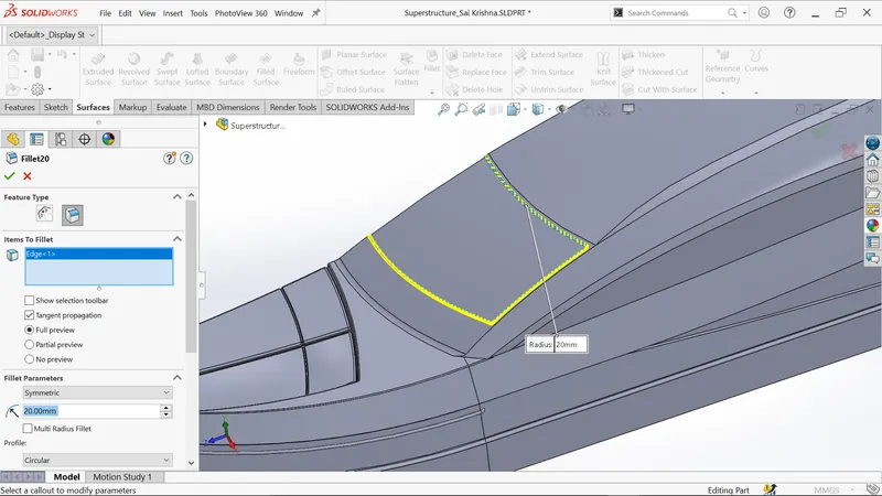
- Apply the fillet on blue edge of 20mm.
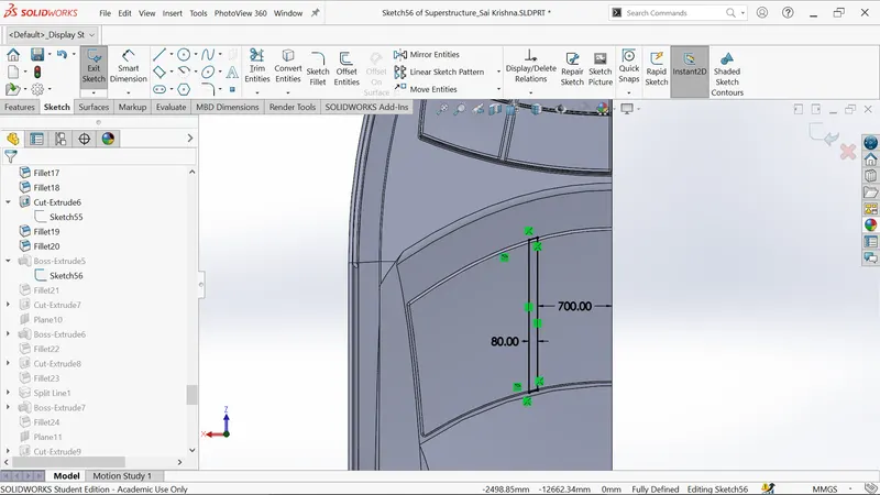
- Create the sketch on bottom surface of superstructure and draw two vertical lines as shown below.
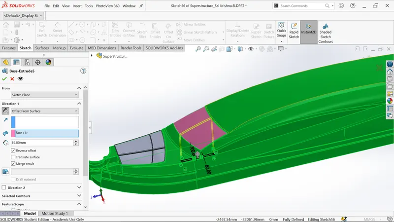
- Generate the extrude is offset from pink surface of 15mm.
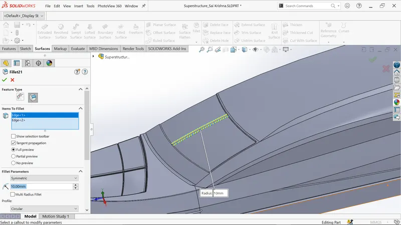
- Add the fillet of 10mm.
- Sketch on top plane and offset the edge of 20 mm.
- Draw the horizontal and verical line as shown below and trim unnecessary lines.
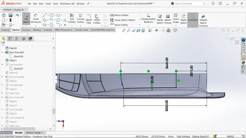
- Generate the cut extrude is offset from pink surface of 60 mm inwards.
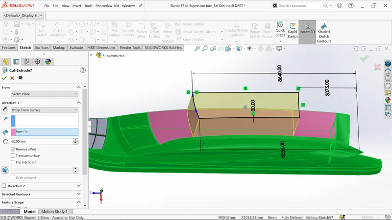
- Create the new plane10 as shown below.
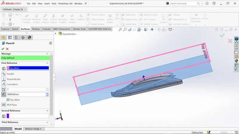
- Sketch on new plane10 and offset the edge of 20 mm.
- Draw the horizontal and verical line as shown below and trim unnecessary lines.
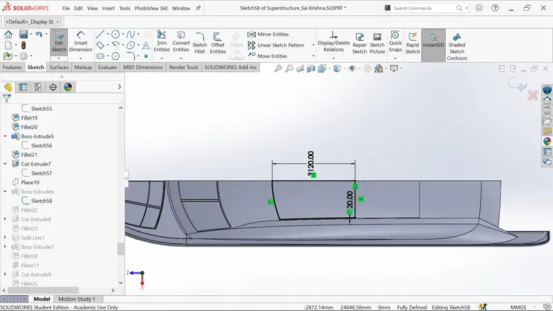
- Generate the cut extrude is offset from pink surface of 60 mm inwards.
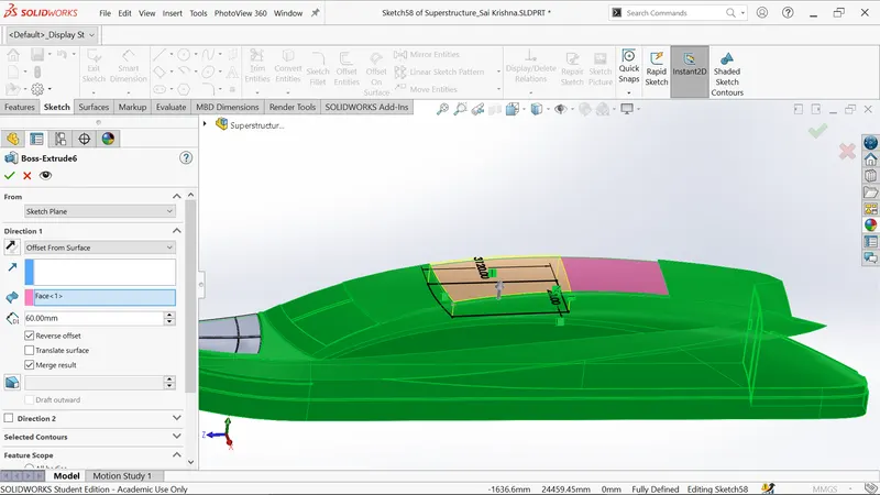
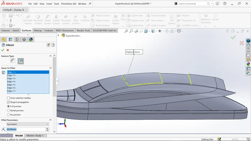
- Add the fillet for the edges of 20mm.
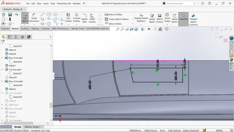
- Sketch on top plane and offset the edge of 680 mm.
- Draw the three lines as shown below and trim unnecessary lines.
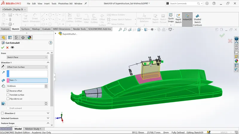
- Generate the cut extrude is offset from pink surface of 10 mm inwards.
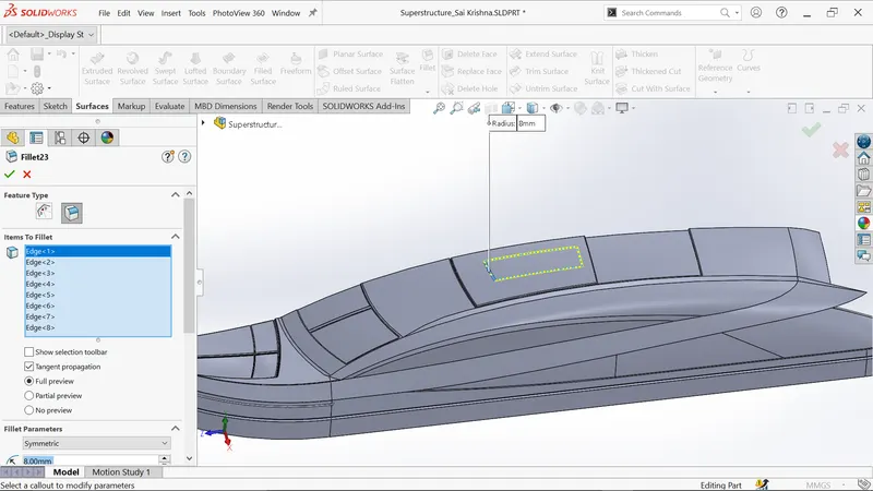
- Add the fillets for the edges of 8mm
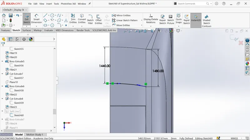
- Sketch on the top plane and draw the spline of exactly matching with blueprint.
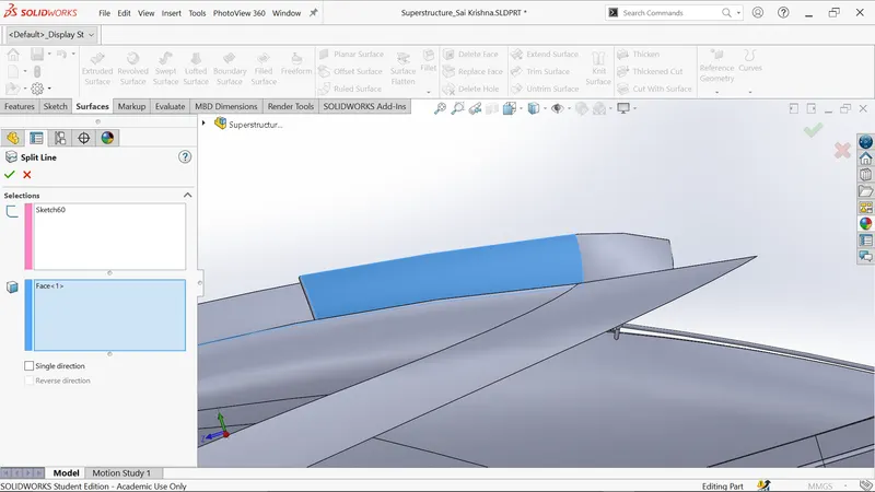
- Create the split line for selected surface.
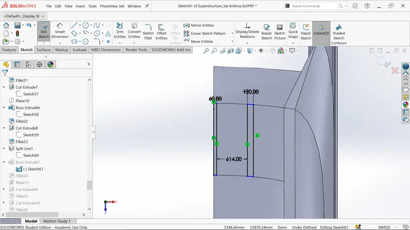
- Sketch on plane10 amnd convert the surface.
- Draw three lines , trim unnecessary lines and complete sketch.
- Generate the extrude is offset from pink surface of 12 mm outwards.
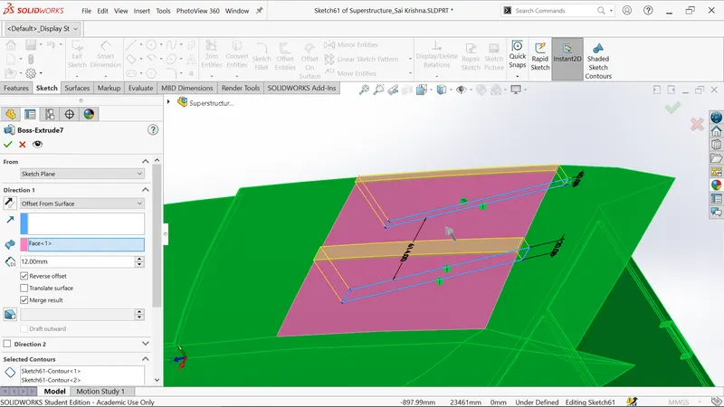
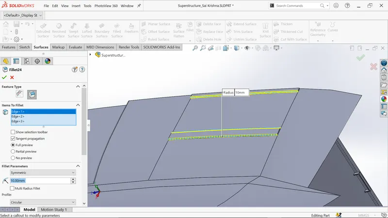
- Add the fillet for outer edges.
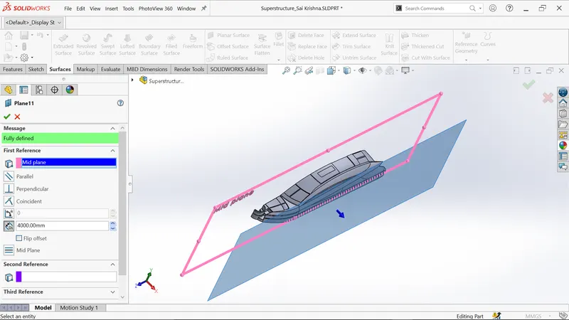
- Create new plane11 by taking midplane as reference of 4000mm.
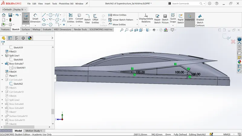
- Create new sketch on plane11 and offset the three window edges of 100mm.
- Generate the cut extrude is offset from pink surface of 30 mm inwards.
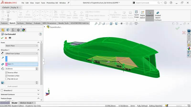
- Add the fillets for outer edges.
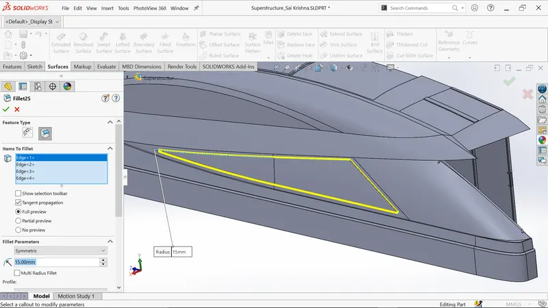
- Create new sketch on plane11 and offset the window edge of 50mm.
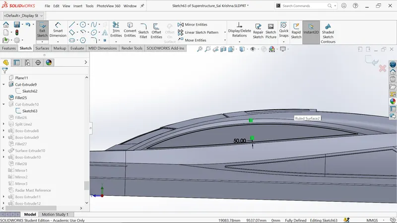
- Generate the cut extrude is offset from pink surface of 30 mm inwards.
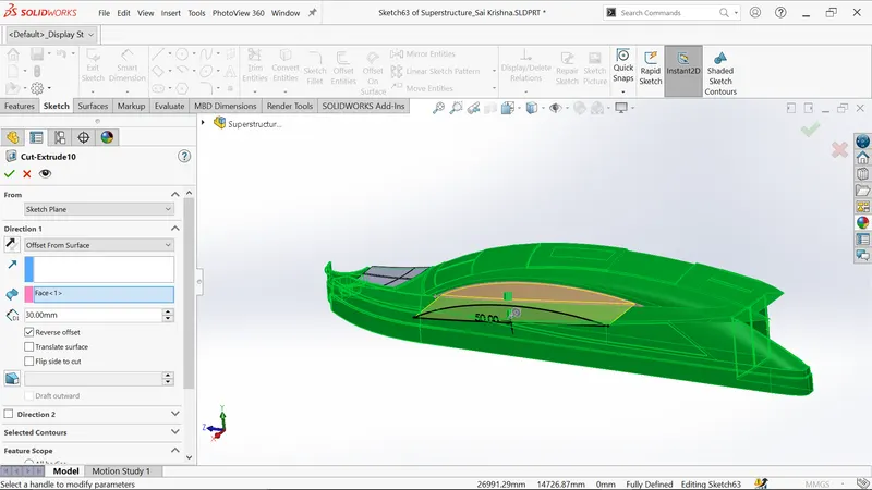
- Add the fillets for outer edges.
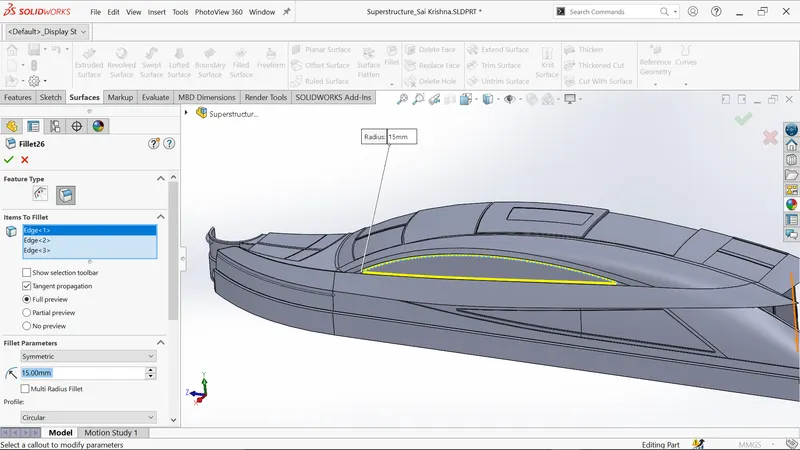
- Create new sketch on plane11 and offset the surface of 100mm inwards.
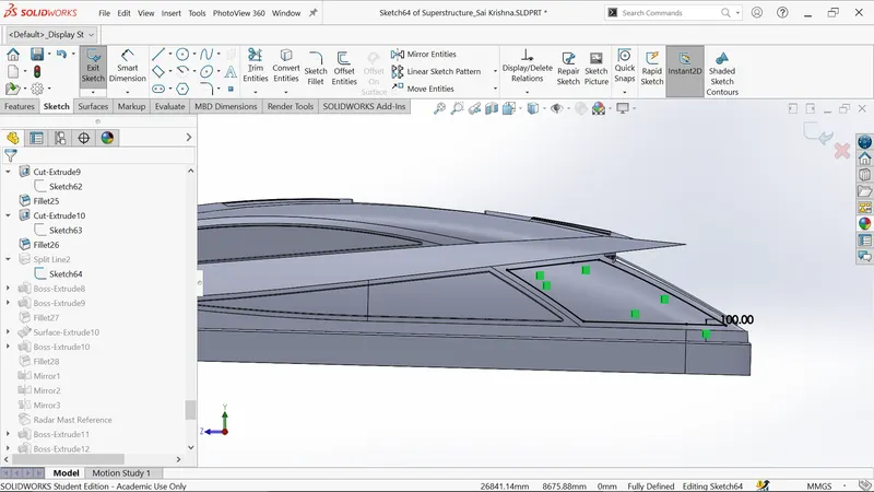
- Create the spline line for sketch 64.
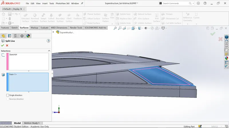
- Sketch on midplane and convert window edge.
- Draw four lines as shown below and trim unnecessary lines.
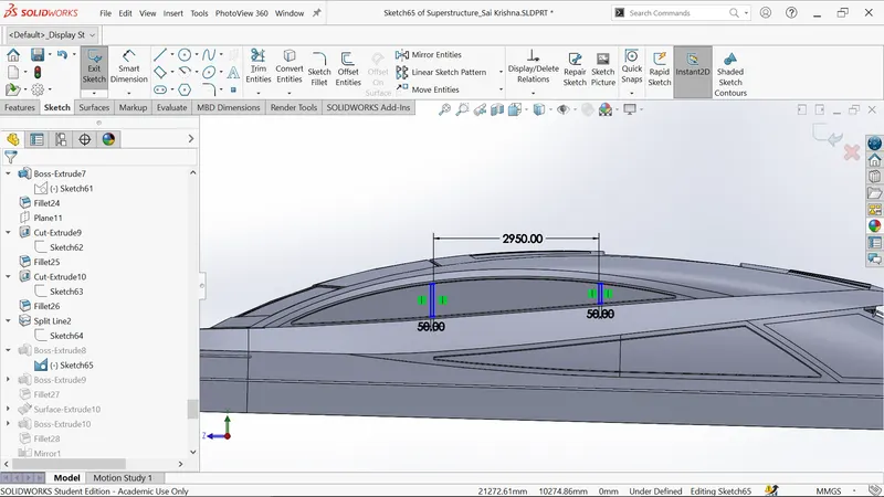
- Generate the boss extrude is offset from pink surface of 20 mm outwards.
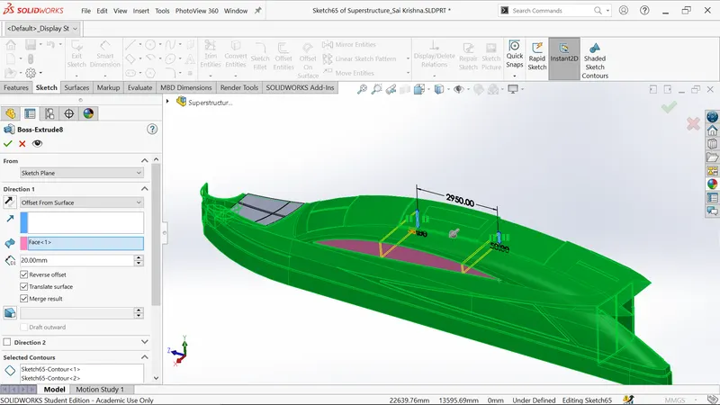
- Sketch on midplane and convert window edge.
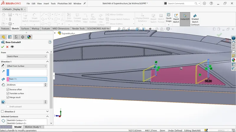
- Draw four lines as shown below and trim unnecessary lines.
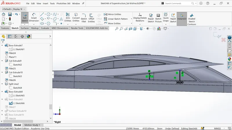
- Generate the boss extrude is offset from pink surface of 20 mm outwards.
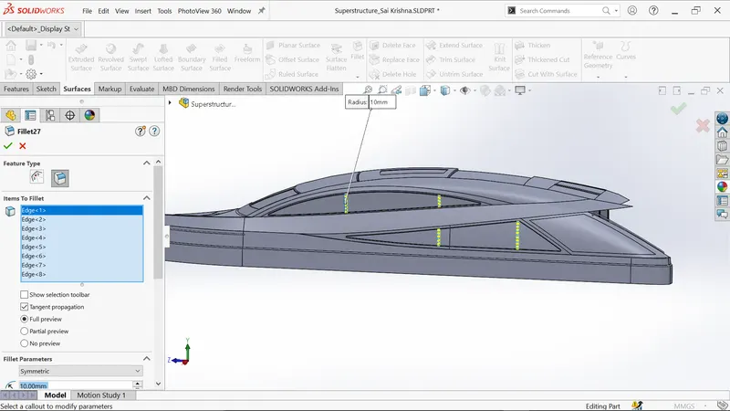
- Add the fillet for edges of 10mm.
- Sketch on midplane and draw the waterline for jacuzzi.
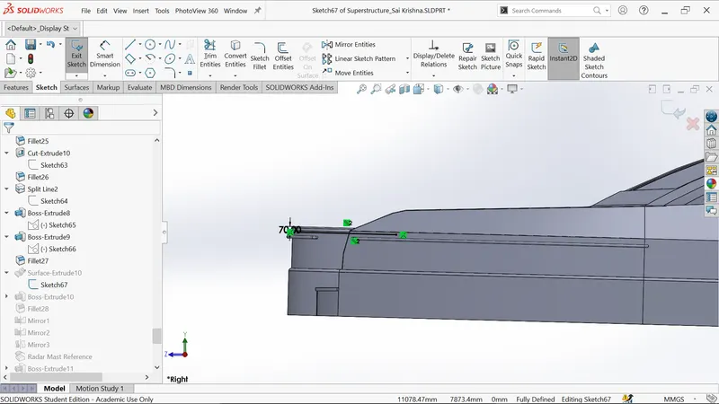
- Generate surface extrude up to next.
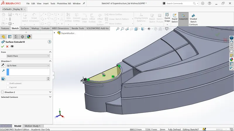
- Sketch on plane4 and draw the half circle, circle as shown below.
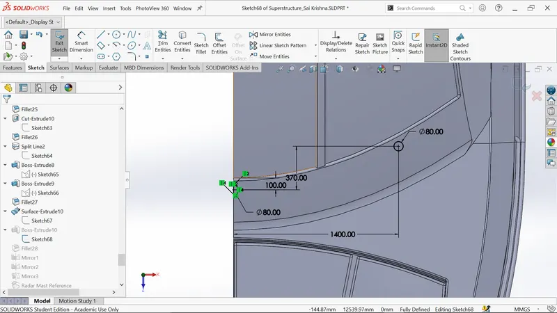
- Generate the boss extrude is offset from pink surface of 40 mm outwards.
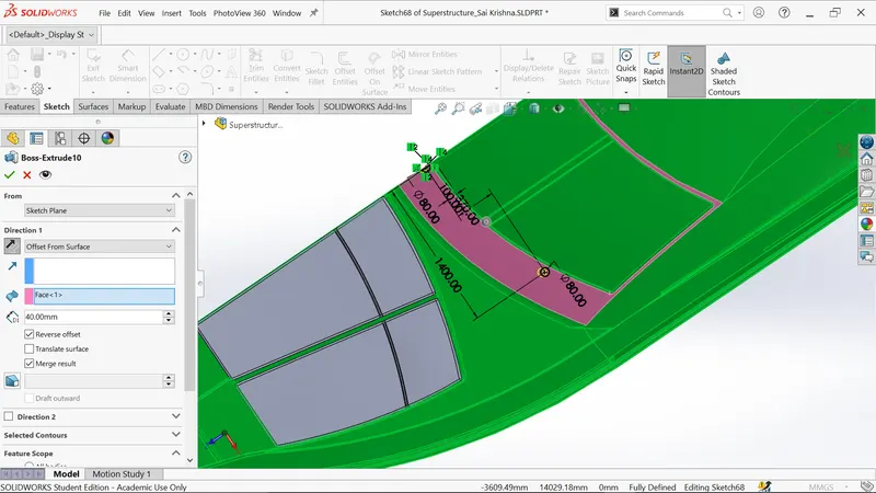
- Apply fillet on two edges edges.
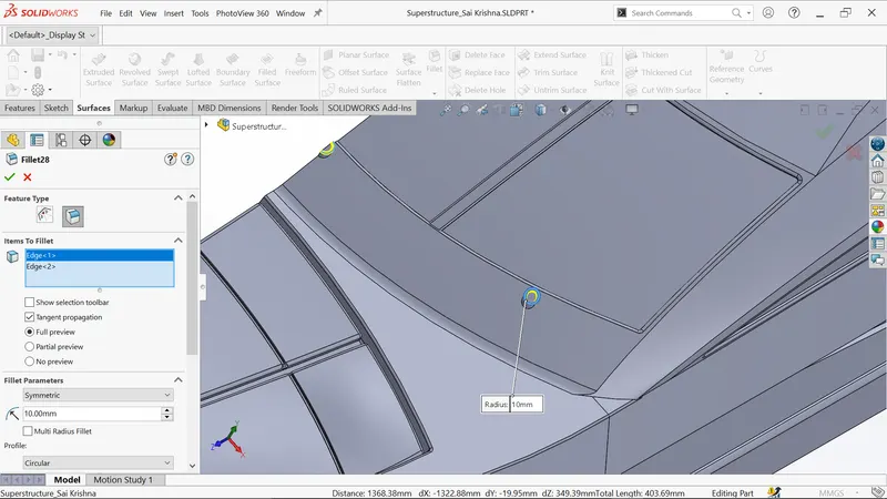
- Mirror the main body of superstructure by selecting midplane as mirror face.
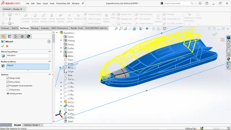
- Mirror the two sundeck matrasses by selecting midplane as mirror face.
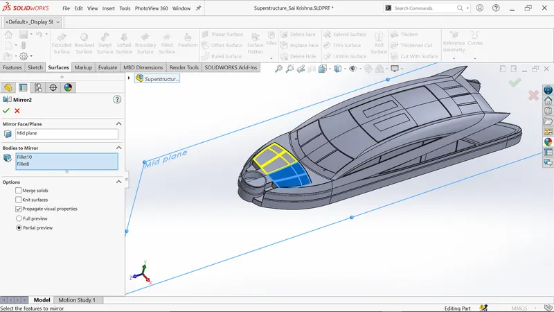
- Mirror the jacuzzi waterline by selecting midplane as mirror face.
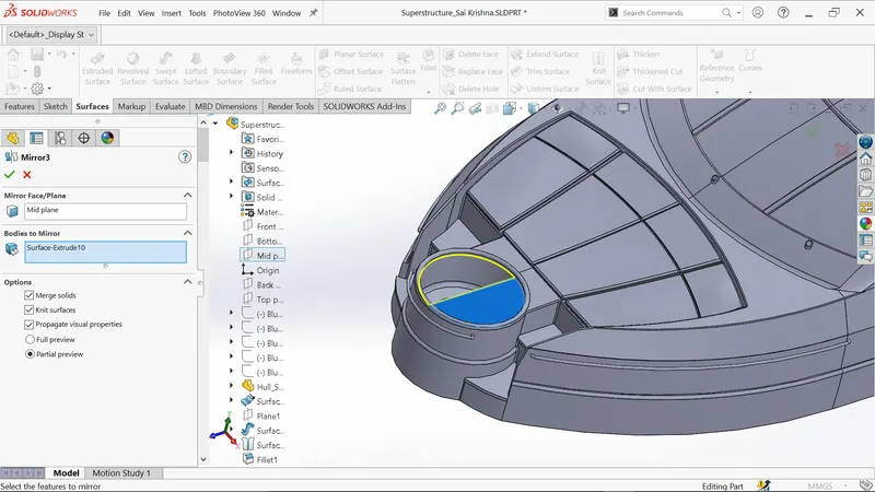
- Offset the selected surface of distance 0mm and rename as radar mast reference which is used designing radar mast model.
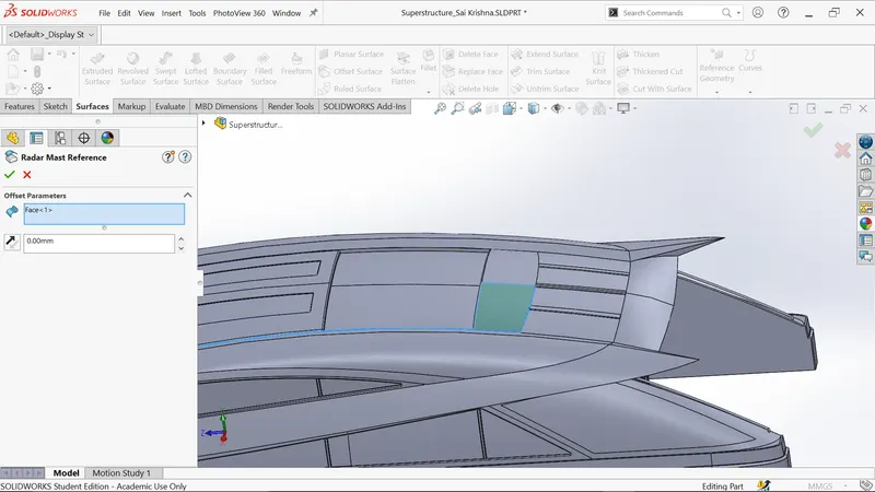
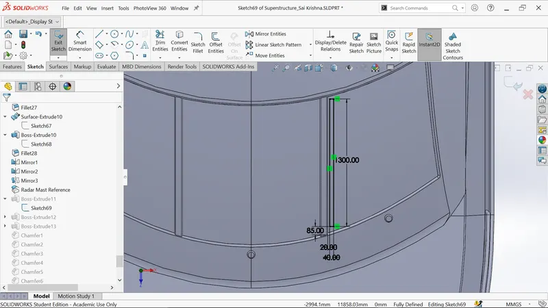
- Sketch on the plane5 and draw the rectangle.
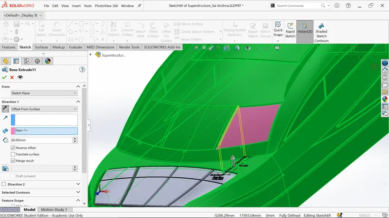
- Generate the boss extrude is offset from pink surface of 60 mm outwards.
- Apply distance distance chamfer of 600mm.
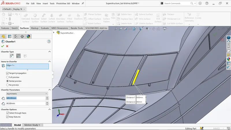
- Apply distance distance chamfer of 600mm.
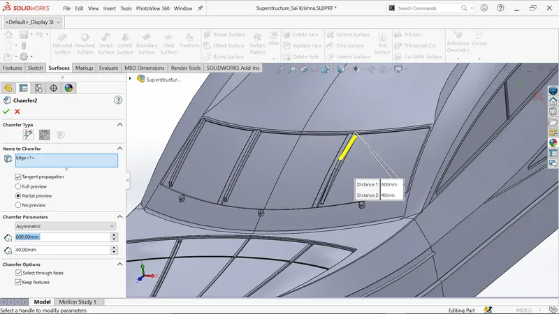
- Similarly repeat the same process for remaining wipers.
- Select the surface of wiper and sketch of offset with 15mm.
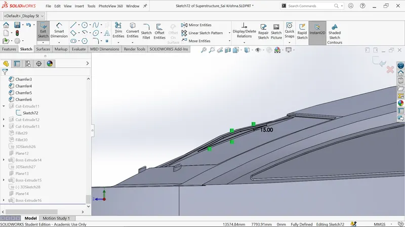
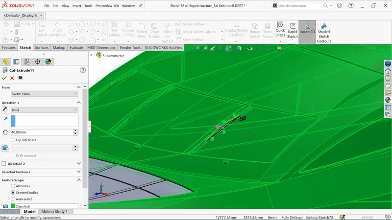
- Generate extrude with depth 40mmm.
- Add the fillets for the edges.
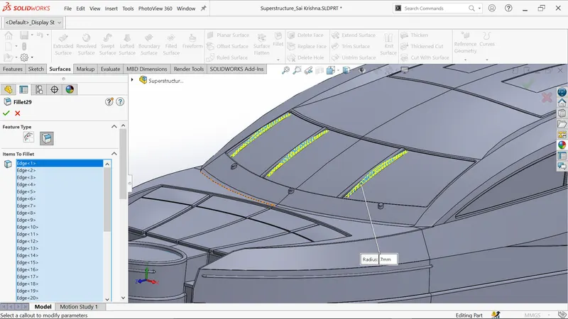
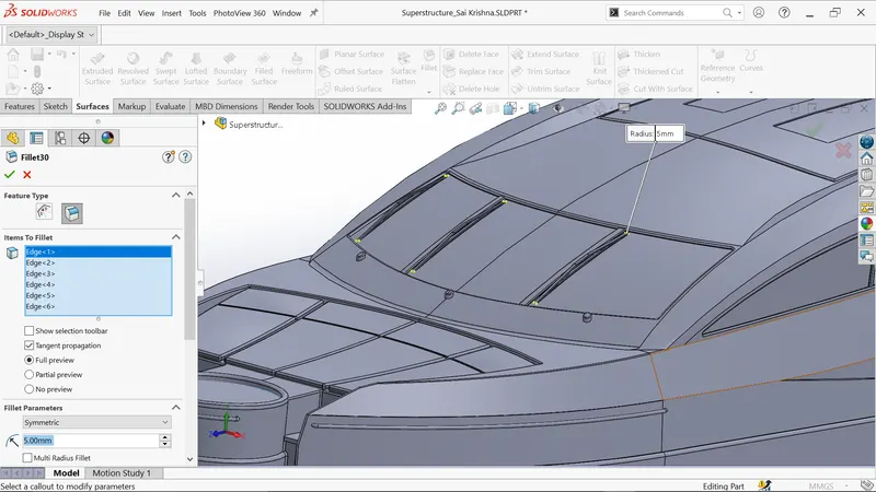
- Add the fillets for the edges of 5mm.
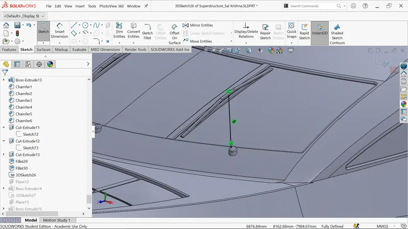
- Create new 3D sketch and draw the line as shown below.
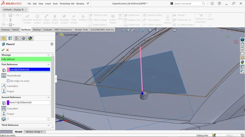
- Create new plane12 as shown below.
- Sketch on new plane 12 and draw the circle of 25mm diameter.
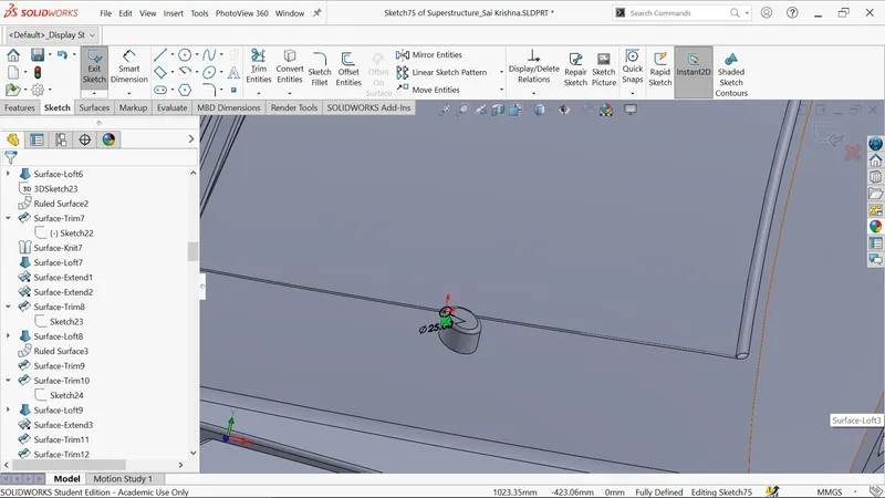
- Generate the extrude as shown below.
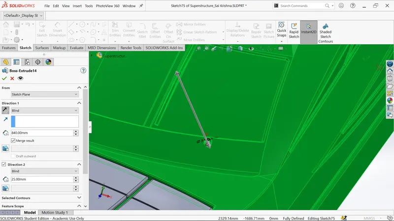
- Repeat this same procedure for remaining two wiper rods but extrude distance will be variable.
- Add the necessary appearnces.
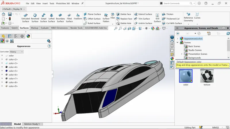
- Finally save the part model as Superstructure.
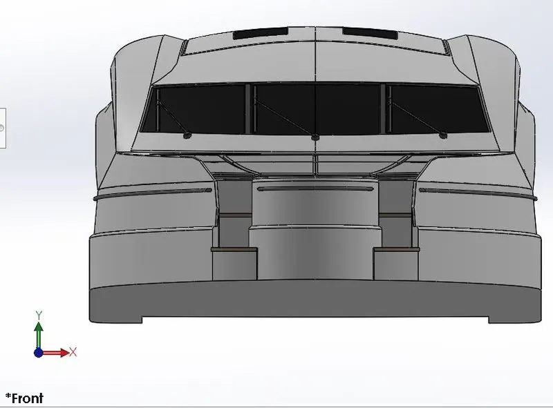
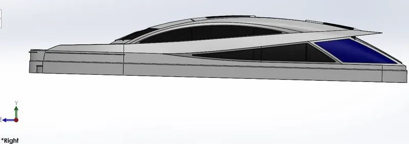
Views of Superstructure:
Front view:
Right view:
Isometric view:
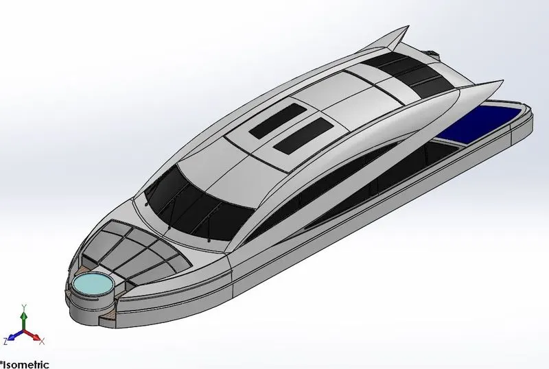
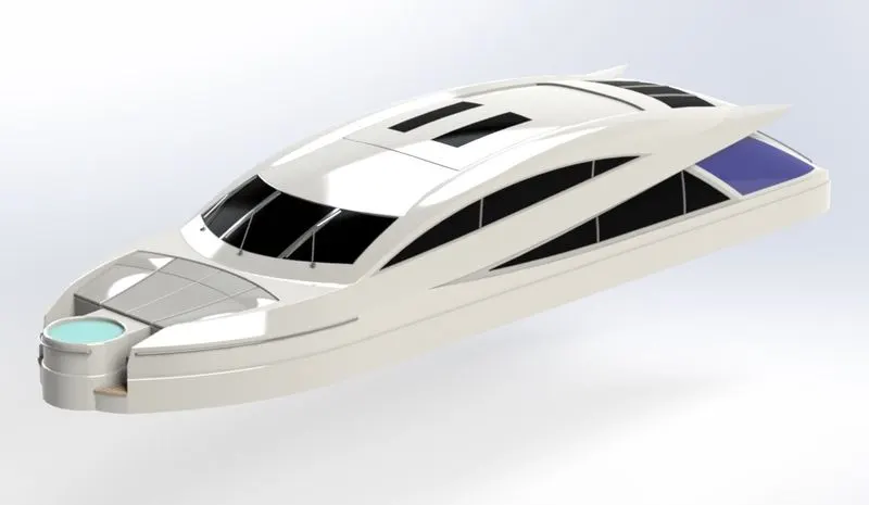
Render image of Superstructure:
Modelling of Radar Mast
Radar mast on the ship is used for navigation purpose and it mainly consists of radar which detects the surrounding objects.
Features used:
Sketch:Sketch creates 2D drawing for the model of having entities like lines,splines,circles etc.
Boss Extrude:Used to extrude 2D sketch into 3D body and it can be done in both forward and reverse direcctions.
Fillet:Used for creating smooth edges in order to avoid sharp edges.
Revolve:Used to create revolve body by selecting centerline as axis.
Sweep:It is used to make extrude body for sweeping curves.
Mirror:Use to mirror the selected features or bodies.
Chamfer:Used for creating sloping surfaces at edges.
Dome:Used to create concave shape on surface.
Shell:Shell feature is used for defining thickness of thick and thin materials.
Procedure to be followed:
- Initially open the blueprint set up file and save the file as Radar Mast.
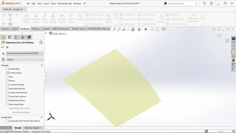
- Import the top surface of superstructure as interface surface by selecting only the surface body.
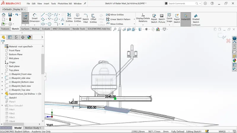
- Create the sketch on midplane and draw the line as per dimensions.
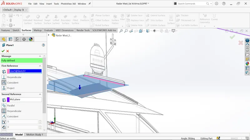
- Create new plane1 as shown below.
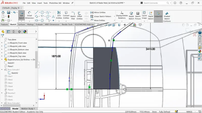
- Sketch on plane1 and normal to top view.
- Draw the four splines without midpoints and line as shown below.
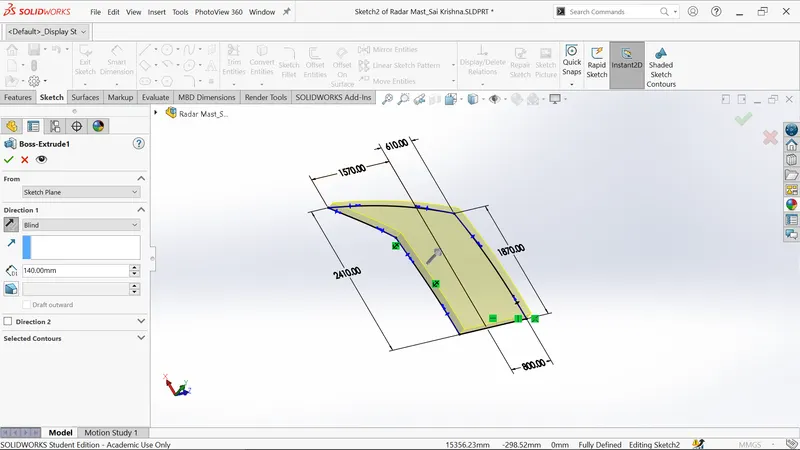
- Generate the extrude of depth 140mm upwards.
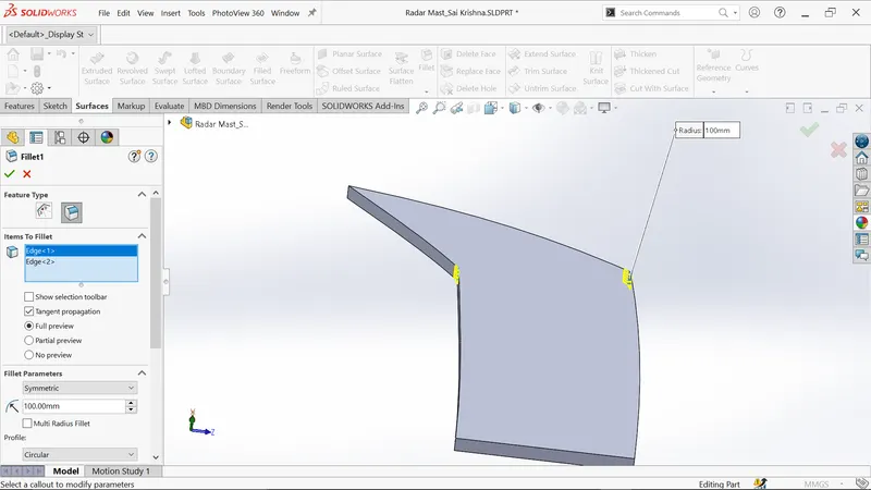
- Apply the fillet for blue edges of 100mm.
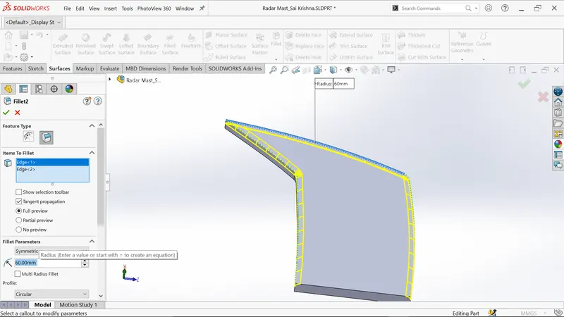
- Apply the fillet for blue edges of 60mm.
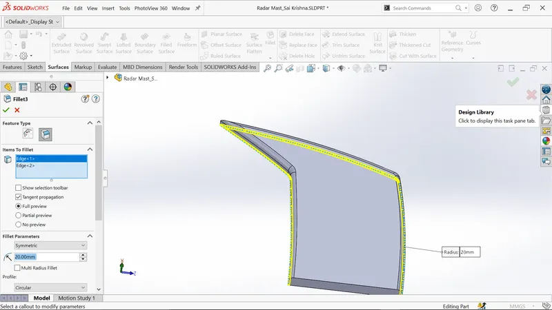
- Apply the fillet for blue edges of 20mm.
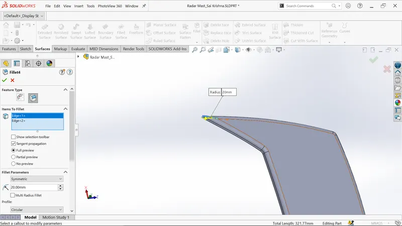
- Apply the fillet for blue edges of 20mm.
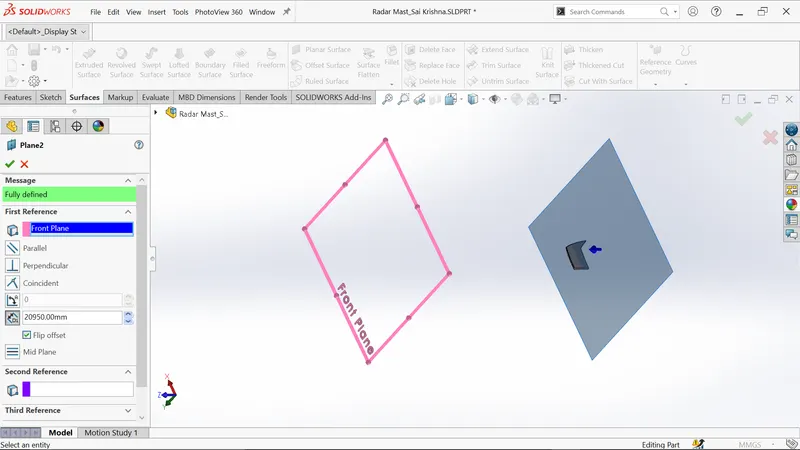
- Create the new plane2 by selecting front plane as reference.
- Sketch on plane2 and normal to front view.
- Draw the lines and 3-point arc as shown below.
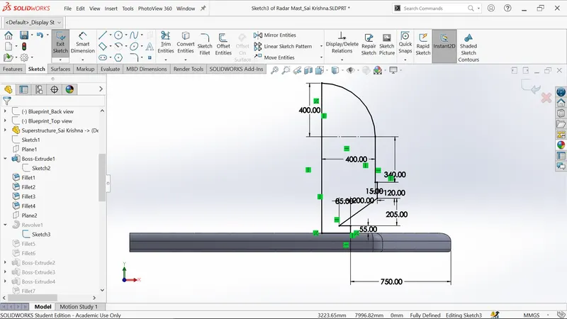
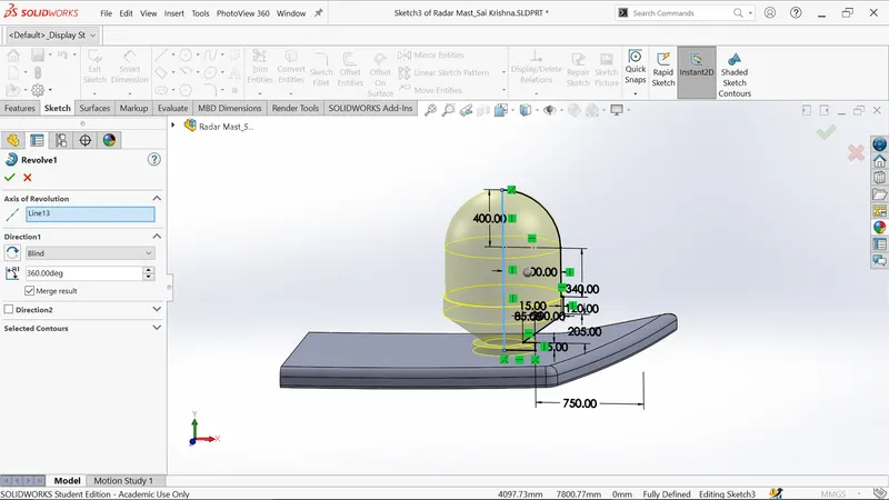
- Create revolve by selecting blue line as axis.
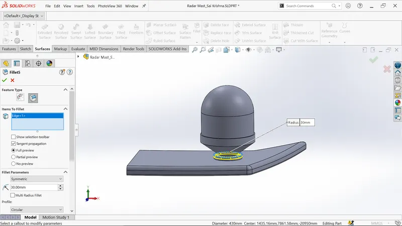
- Apply the fillet for blue edge of 30 mm.
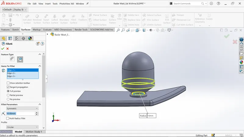
- Apply the fillet for blue edges of 10 mm.
- Sketch on top surface and draw circle of diameter 50mm as shown.
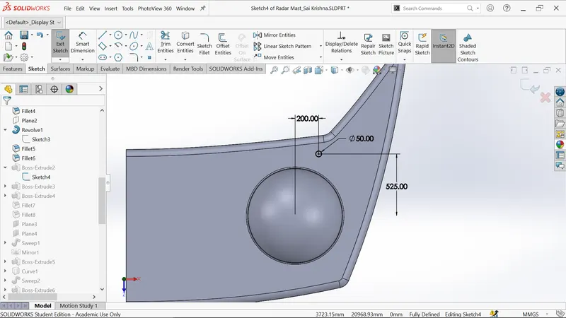
- Generate the extrude of depth 345mm.
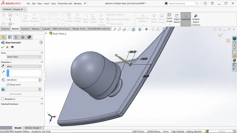
- Create sketch on above extrude surface and draw circle as shown.
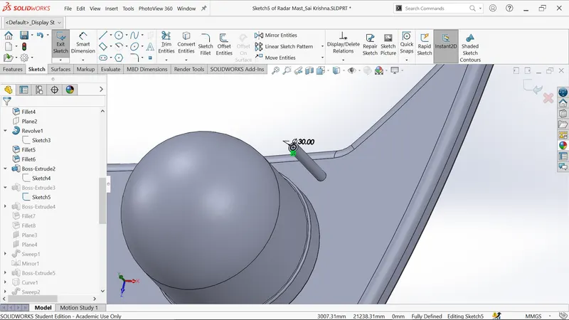
- Generate the extrude of depth 50mm.
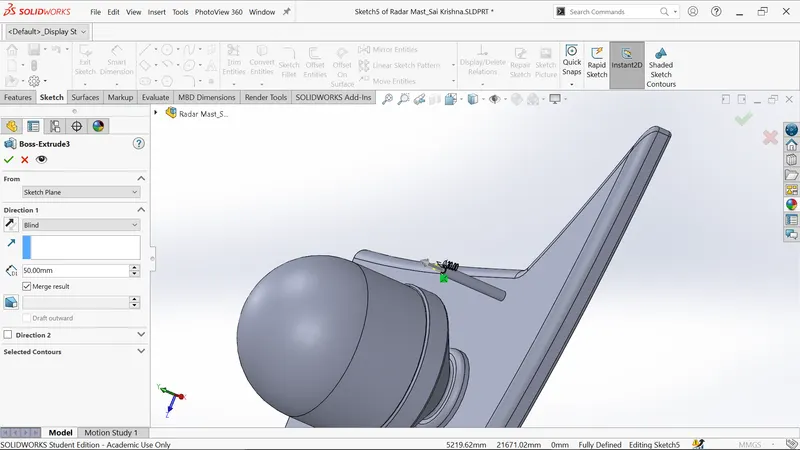
- Create sketch on above extrude surface and draw circle as shown.
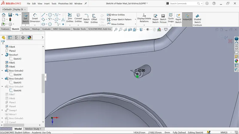
- Generate the extrude of depth 1800mm.
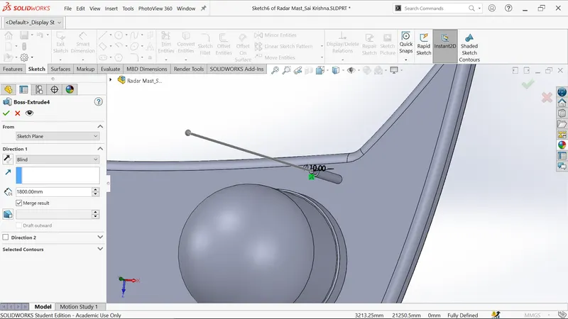
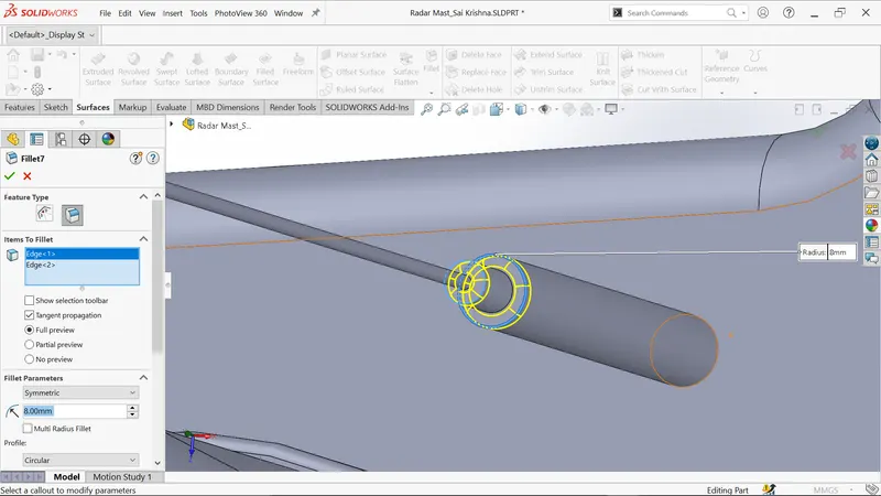
- Apply the fillet for blue edges of 8 mm.
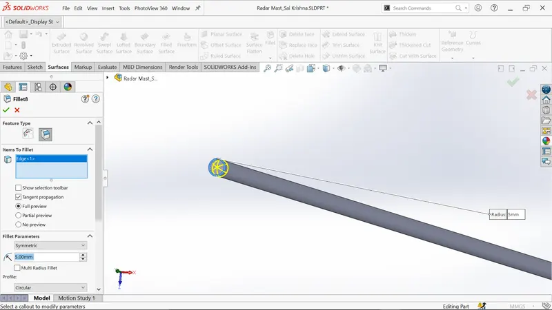
- Apply the fillet for blue edge of 5 mm.
- Create the new plane3 by selecting plane2 as reference.
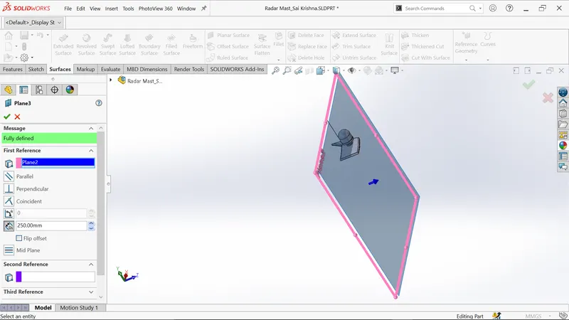
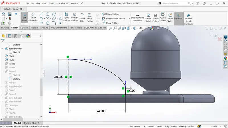
- Sketch on plane3 as view normal to front view and draw centerline.
- Draw the vertical line and spline as shown below.
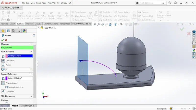
- Create the new plane4 as shown below
- Sketch on plane4 and draw circle of diameter 60mm.
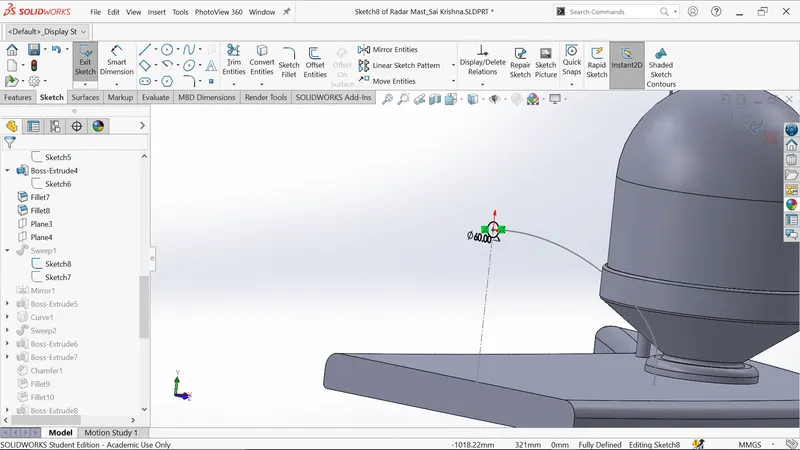
- Create the sweep using sketch8 and sketch7.
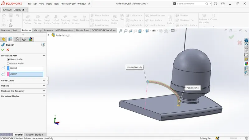
- Mirror the sweep1 by selecting plane2 as mirror face.
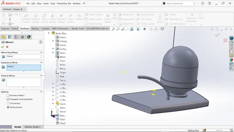
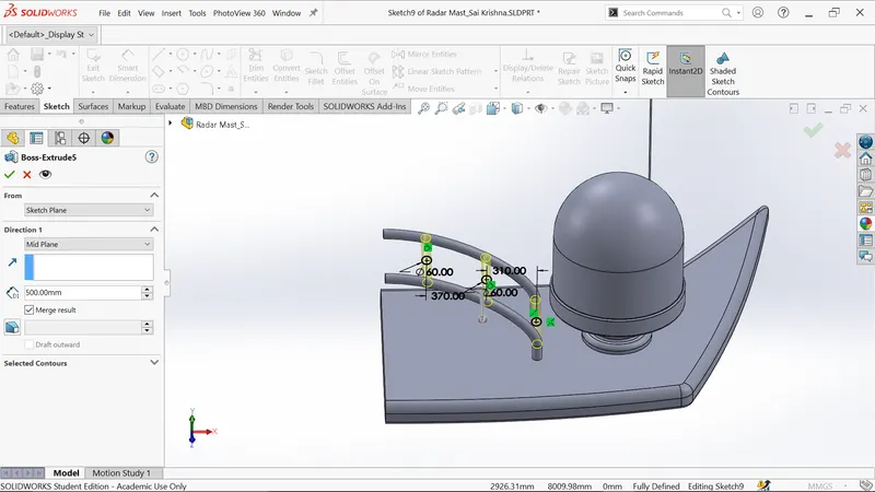
- Sketch on plane2 and draw three circles as shown in picture.

- Generate the extrude in midplane direction.
- Sketch on midplane and draw two lines as shown in picture.
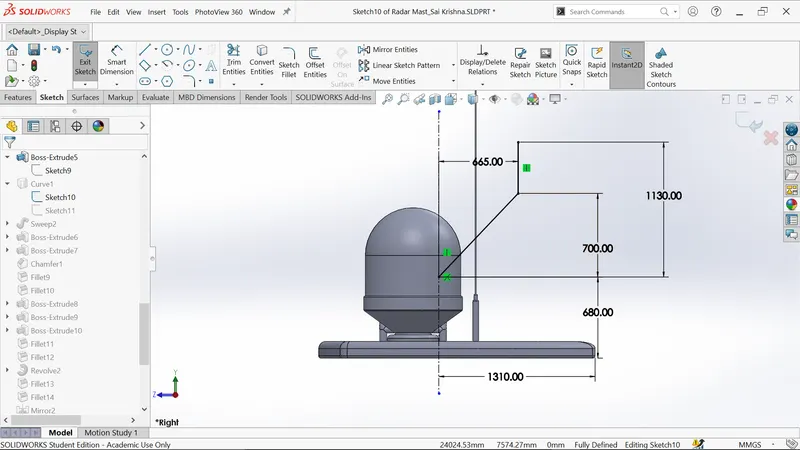
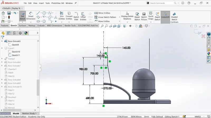
- Create sketch on plane2 and draw centerline as shown below.
- Draw the two lines and center point arc as shown.
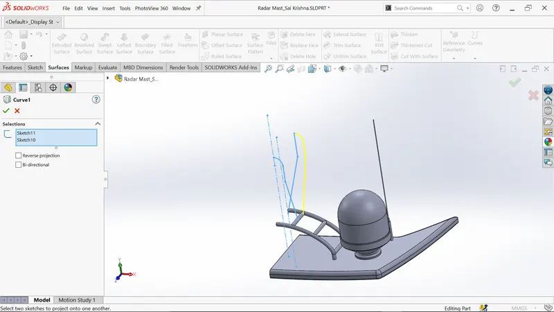
- Project the sketch10 and sketch11 by using project curve feature.
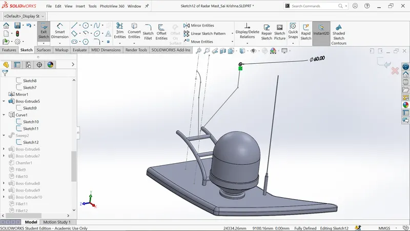
- Sketch on midplane and draw circle as shown in picture.
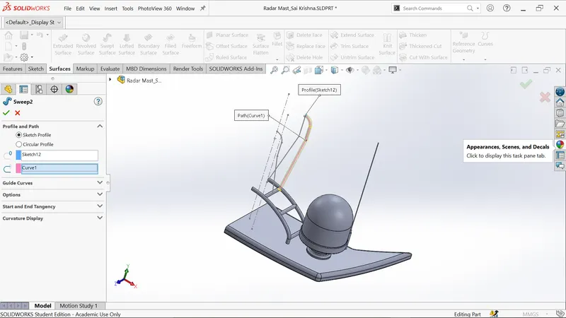
- Create the sweep using sketch12 and curve1.
- Sketch on top surface and draw half circle as shown.
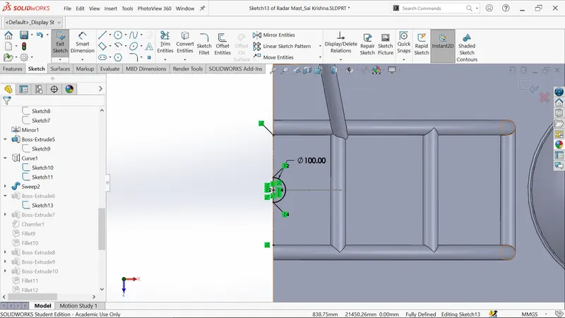
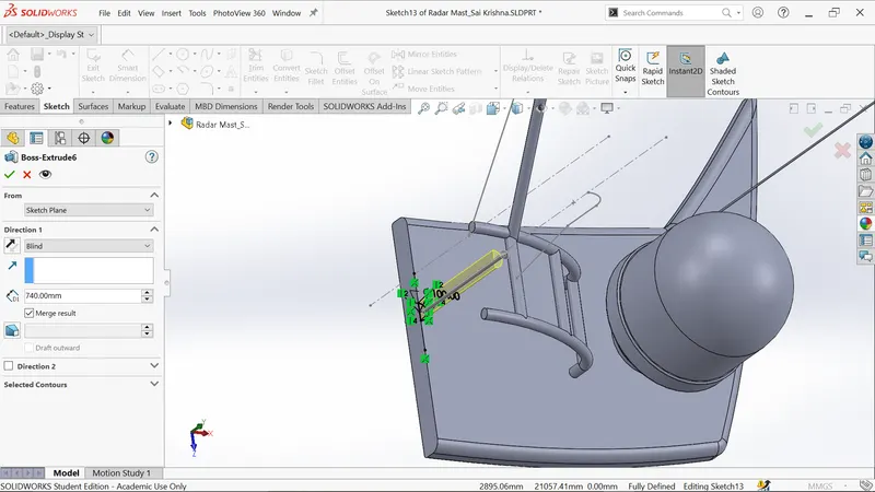
- Generate the extrude upto 740mm outwards.
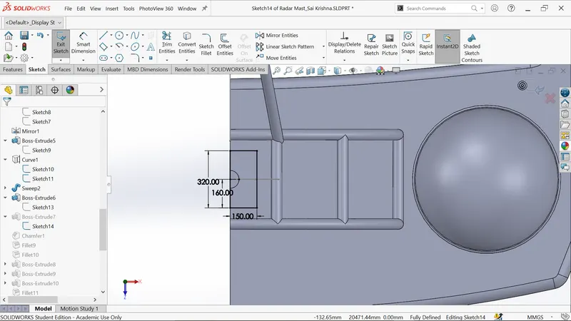
- Sketch on above extrude surface and draw rectangle as shown.
- Generate the extrude upto 200mm outwards.
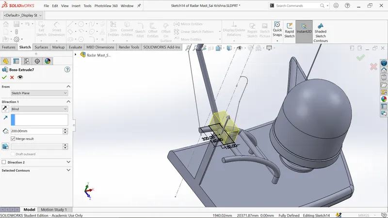
- Apply the distance distance chamfer as shown.
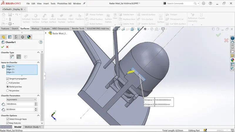
- Add the fillet for blue edges of 24 mm as shown in below pictures.
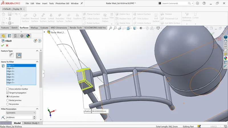
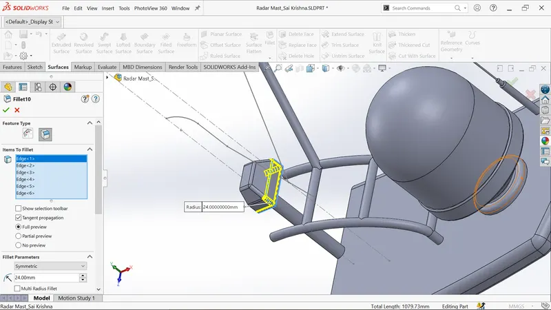
- Sketch on midplane and draw rectangle as shown in picture.
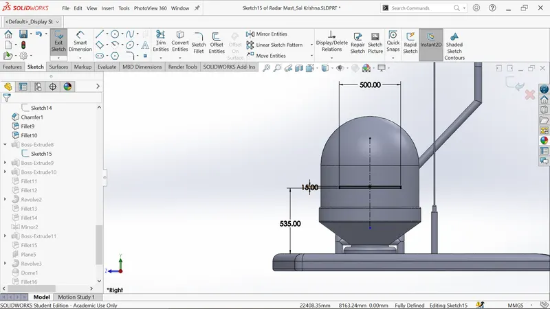
- Generate the extrude upto pink surface as shown.
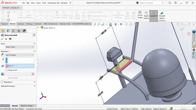
- Sketch on above extrude surface and draw half circle as shown.
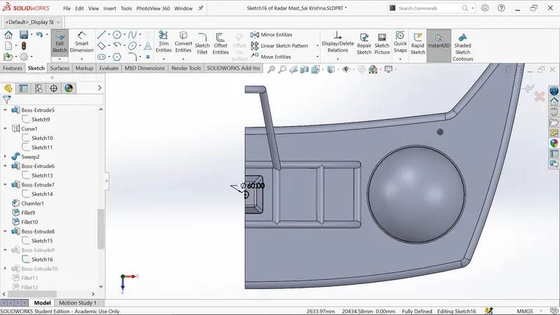
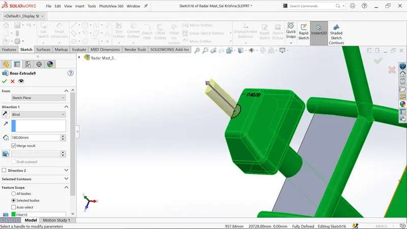
- Generate the extrude of depth 180mm upwards.
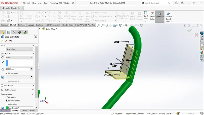
- Sketch on midplane and draw lines as shown in picture.
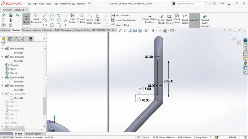
- Generate the extrude of depth 150mm inwards.
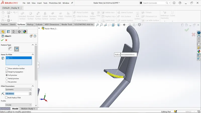
- Apply the fillet for blue edge of 100mm.
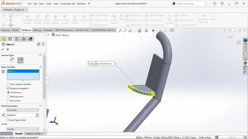
- Apply the fillet for blue edge of 30mm.
- Sketch on midplane and draw lines as shown in picture.
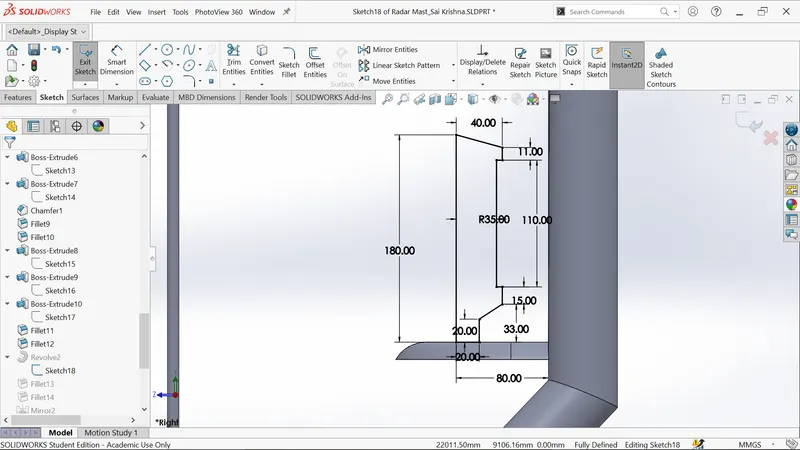
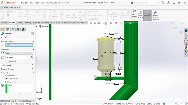
- Generate the revolve by selecting blue line as axis.
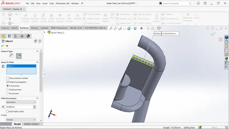
- Apply the fillet for blue edge of 10mm.
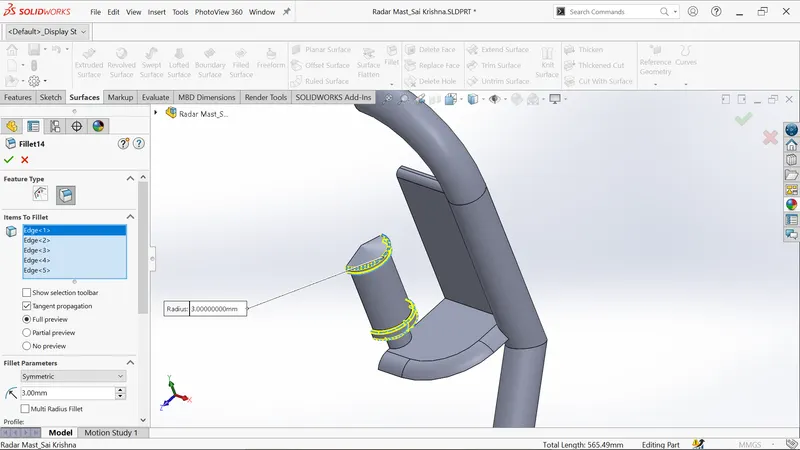
- Apply the fillet for blue edges of 3mm.
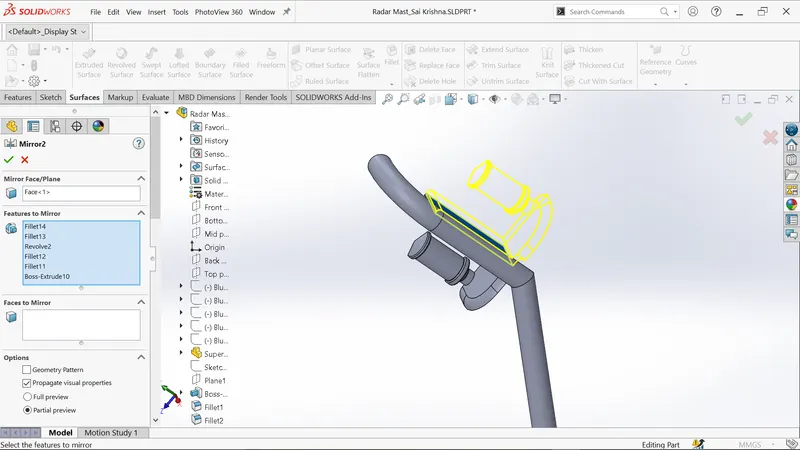
- Mirror the features as shown below.
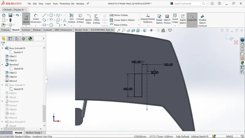
- Create sketch on bottom surface of superstructure and draw rectangle as shown.
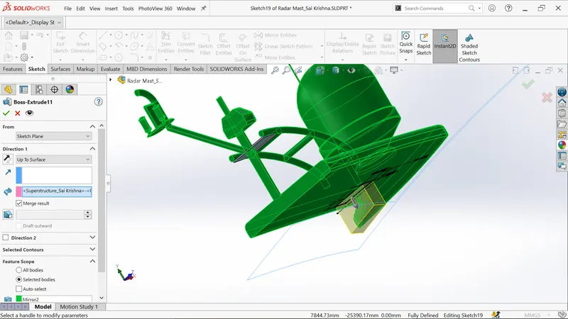
- Generate the extrude upto to surface as shown.
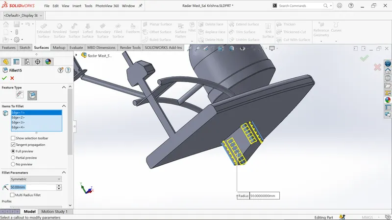
- Apply the fillet for blue edges of 50mm.
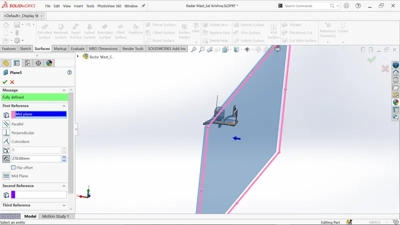
- Create the new plane5 by taking midplane as reference of distance 270mm.
- Sketch on new plane5 and draw lines, spline as shown in picture.
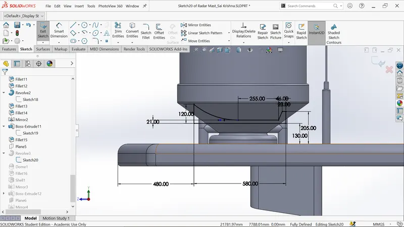
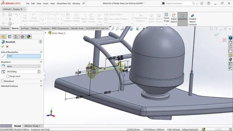
- Generate the revolve by selecting blue line as axis.
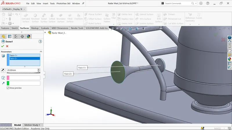
- Apply the dome feature on the two outer faces as shown.
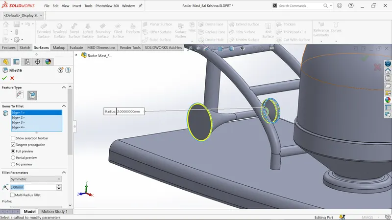
- Apply the fillet for blue edges of 3mm.
- Create the shell for outer face ass shown below.
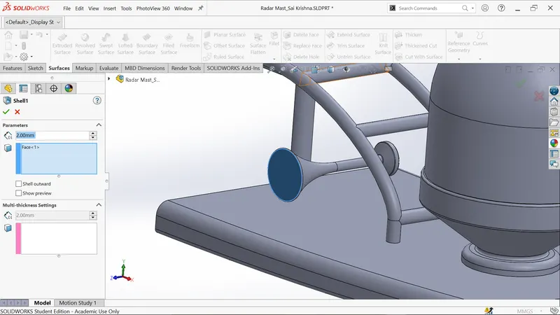
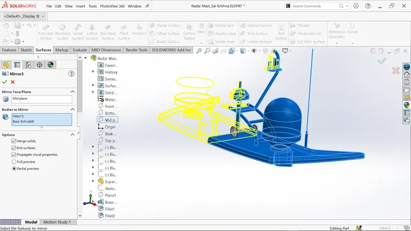
- Mirror the bodies by selecting midplne a mirror face.
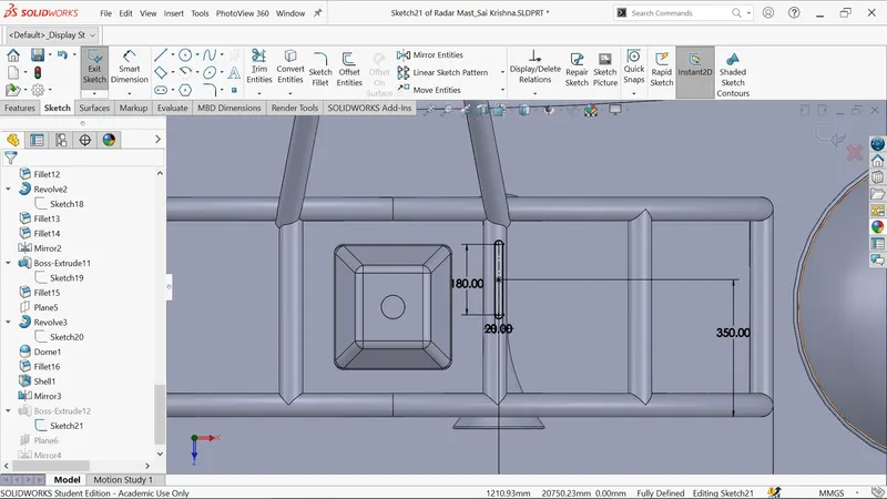
- Sketch on top surface of superstructure and draw straight slot as shown.
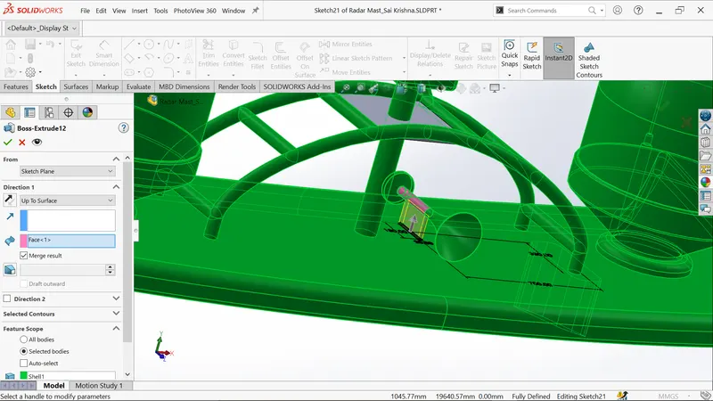
- Generate the extrude upto to pink surface as shown.
- Create new plane6 as shown below.
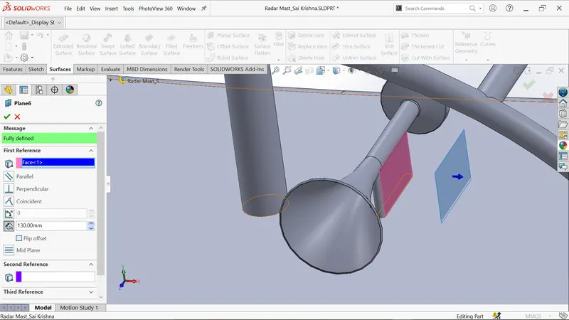
- Mirror the horn by selecting plane6 as mirror face.
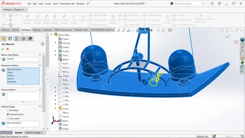
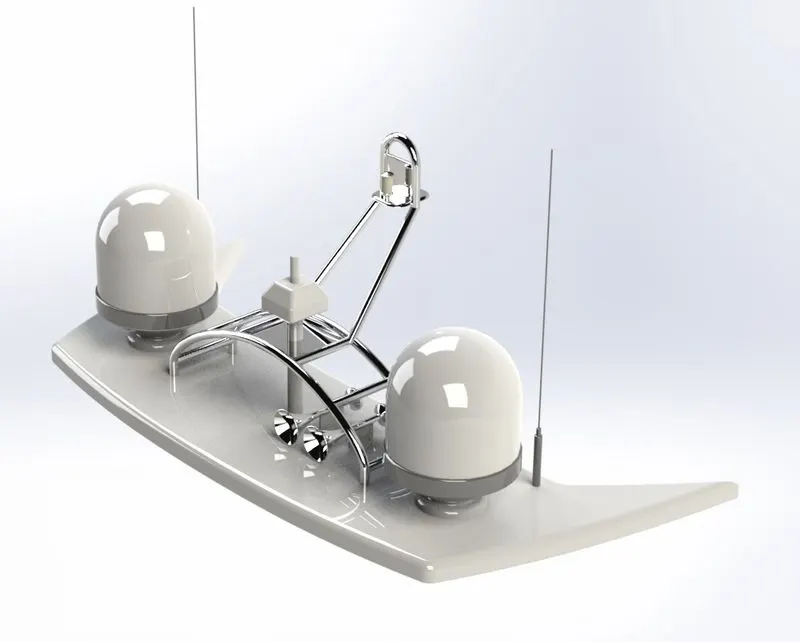
- Apply the appearances for radars,antenas,lights as shown.
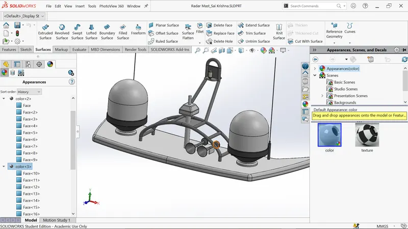
- Finally save the part model as Radar Mast.
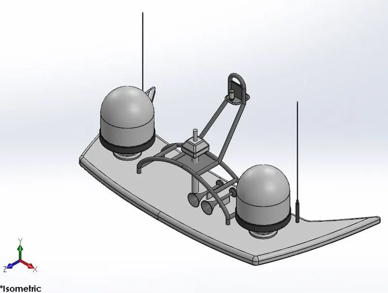
Views of Radar Mast:
Front view:
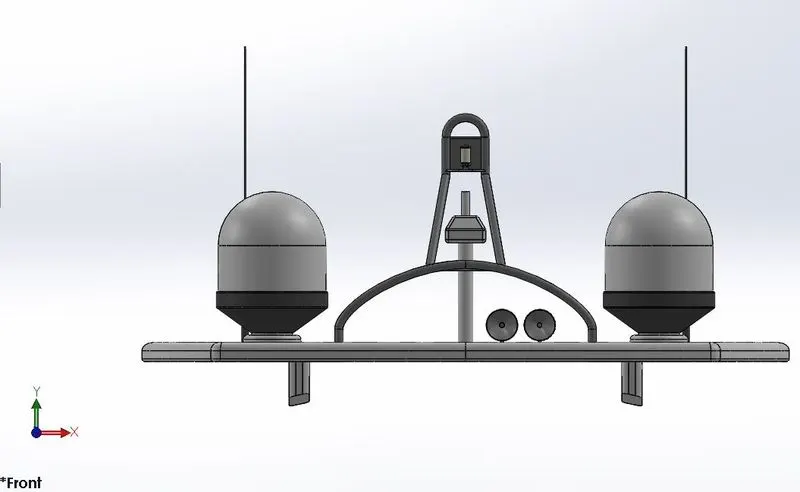
Right view:
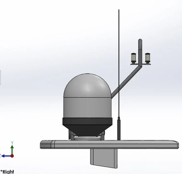
Isometric view:
Render image of Radar Mast:
ASSEMBLY OF AN SUNSEEKER PREDATOR YACHT
Assembly is a process of inserting all the individual part model components into single part file.In solidworks assembly can be done by using different mate relations.
Features used for creating assembly:
Insert component:This feature is used for recalling each individual model part file during the assembly.
Mate:It is the most important feature used in solidworks during the assembly because it creates the geometric relations between assembly components.
Mate relations used:
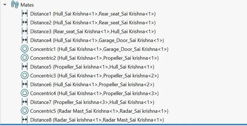
- Concentric
- Coincident
Procedure to be followed for assesmbly:
- First go to start -program,select assemby template file and open it.
- Import the hull and it is fixed automatically as shown below.
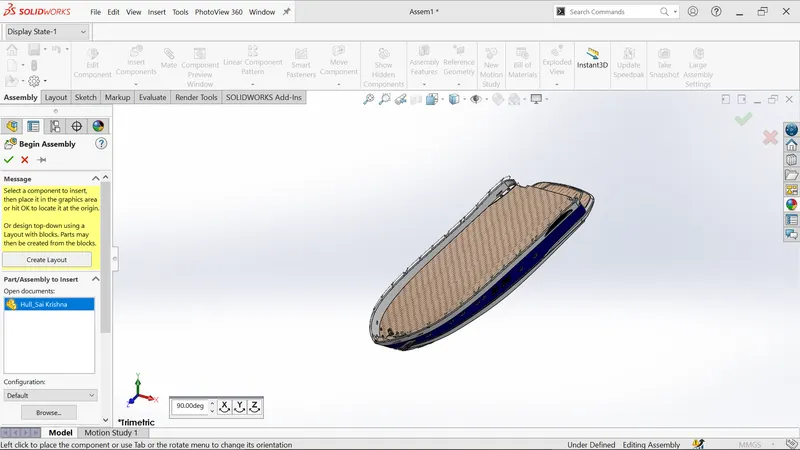
- Import the superstructure and it is fixed automatically as shown below.
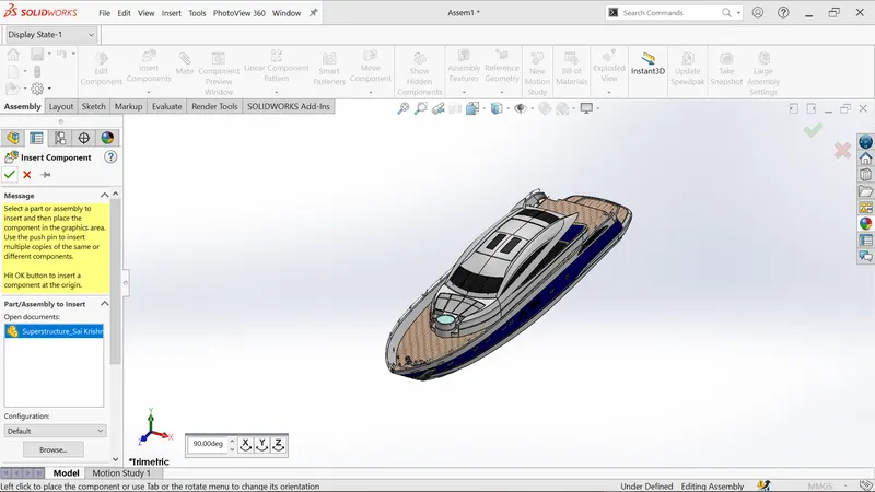
- Import the radar and it is fixed automatically as shown below.
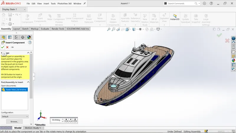
- Import the front seat and it is fixed automatically as shown below.
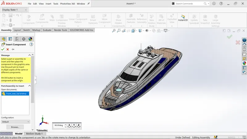
- Import the middle seat and it is fixed automatically as shown below.
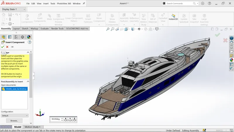
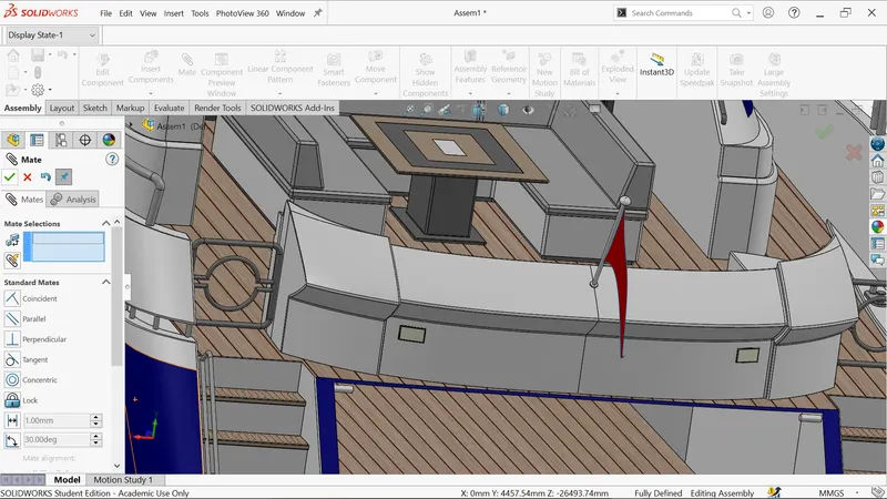
- Import the rear seat and click anywhere on working scene.
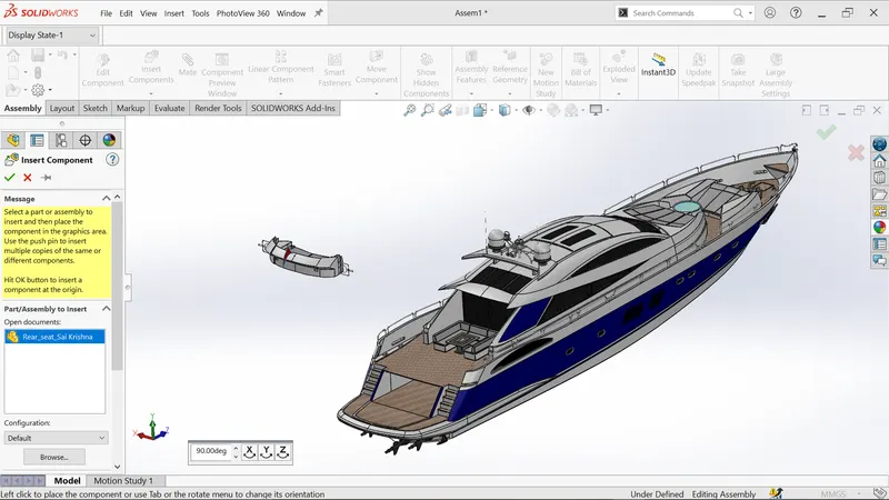
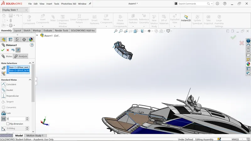
- Apply the coincident mate between deck surface and rear seat bottom surface as shown.
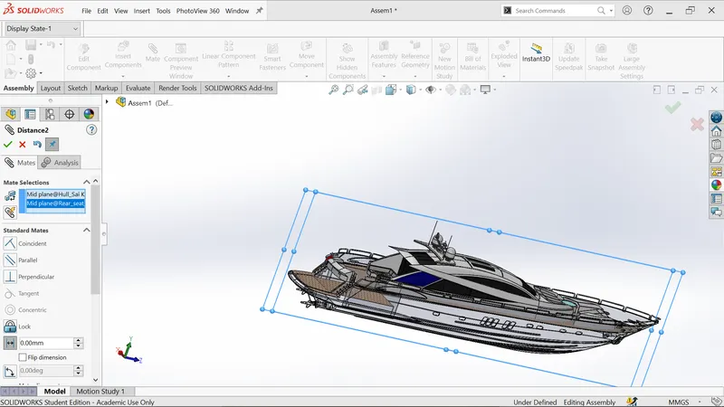
- Apply the coincident mate between midplane of hull and midplane of rear seat as shown.
- Apply the coincident mate between two black points as shown.
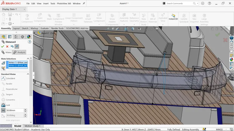
- Finally rear seat fixed properly.
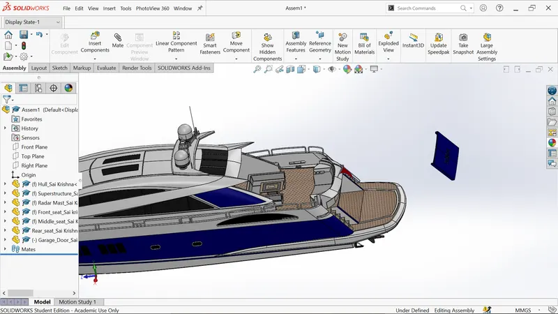
- Import the garage door and click anywhere on working scene.
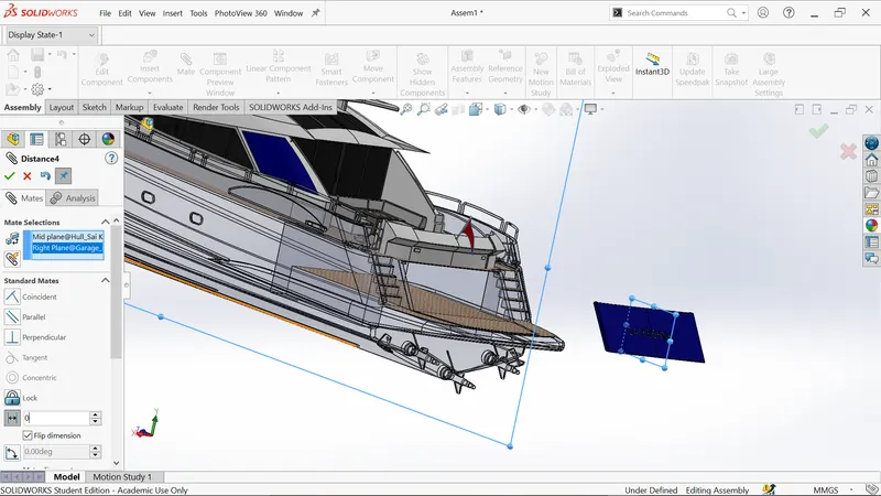
- Apply the coincident mate between midplane of hull and right plane of garage door as shown.
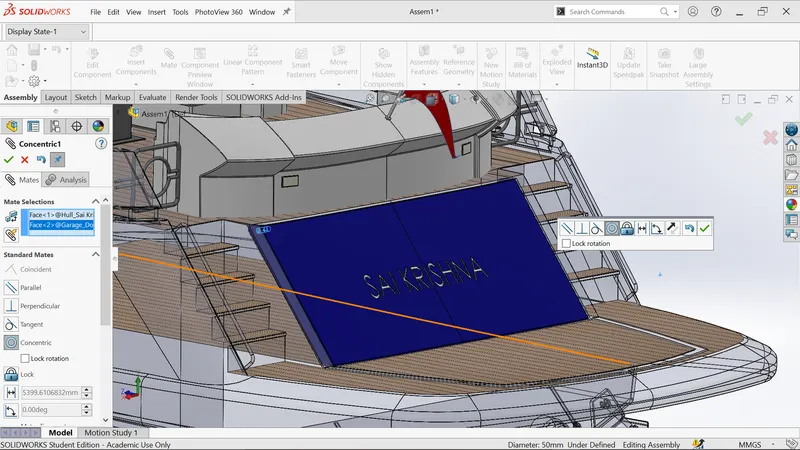
- Apply the concentric mate between blue hinge tube of hull and blue hinge hole of garage door as shown.
- Import the propeller and click anywhere on working scene.
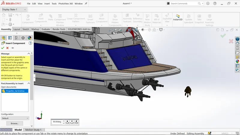
- Apply the concentric mate between blue axis of of hull and blue propeller hole as shown.
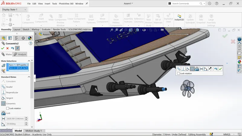
- Apply the coincident mate between blue surface of hull and blue surface of propeller as shown.
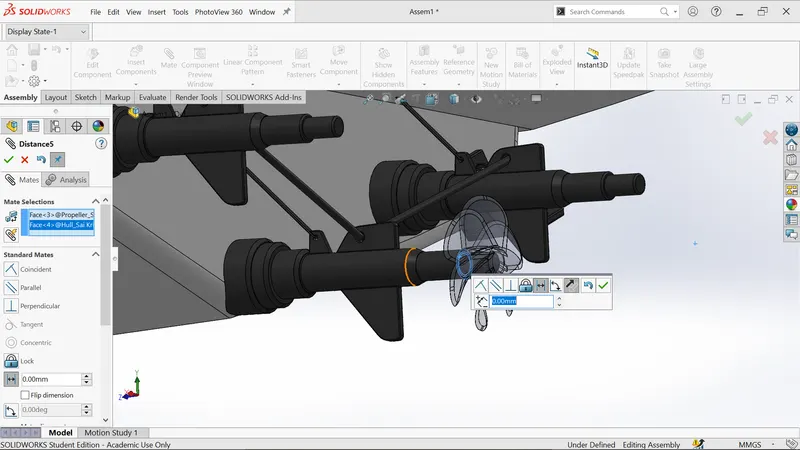
- Import and mate other two propellers in the same way.
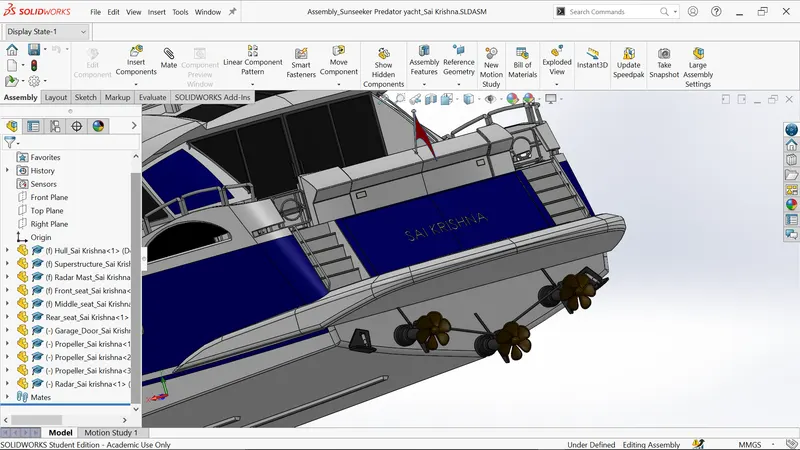
- Import the radar and click anywhere on working scene,.
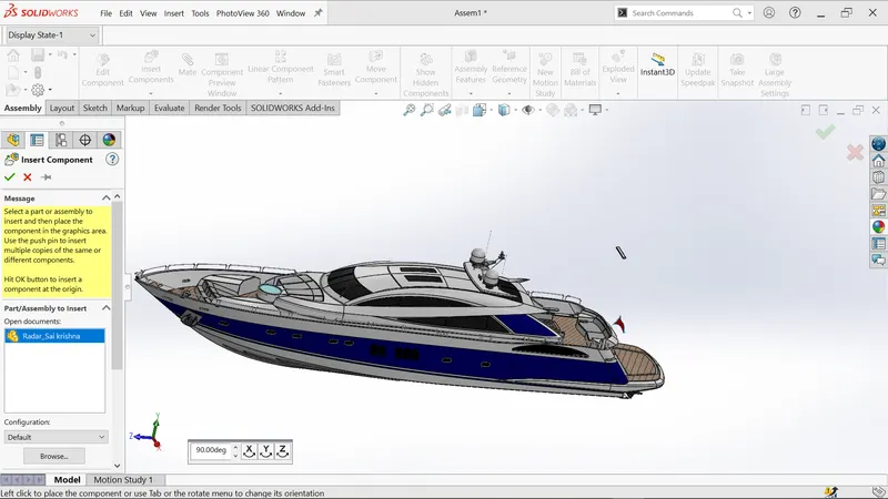
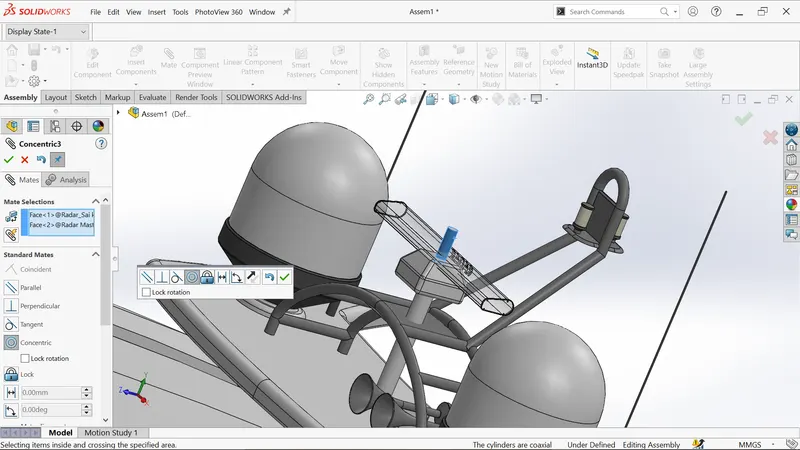
- Apply the concentric mate between blue axis of radar mast and blue hole of radar as shown.
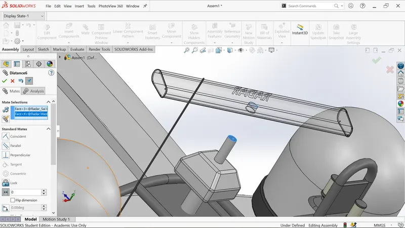
- Apply the coincident mate between blue surface of radar mast and blue surface of radar as shown.
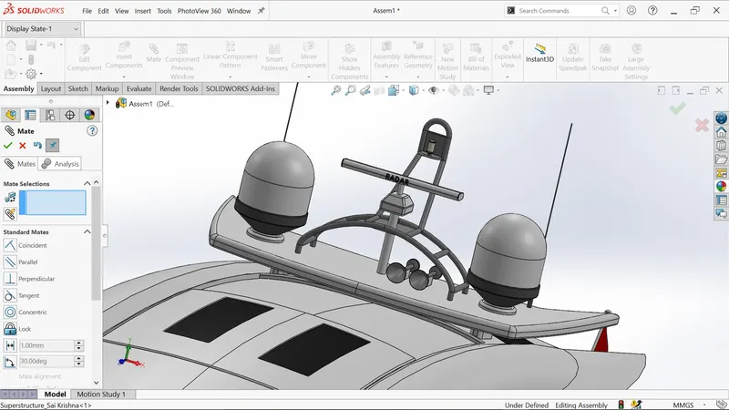
- Finally save the file as yacht assembly.
Assembly mates of an yacht:
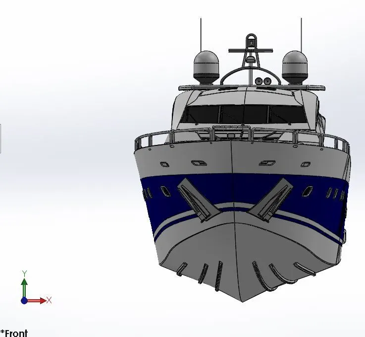
Views of Yacht Assembly:
Front view:
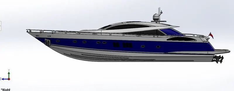
Right view:
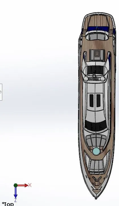
Top view:
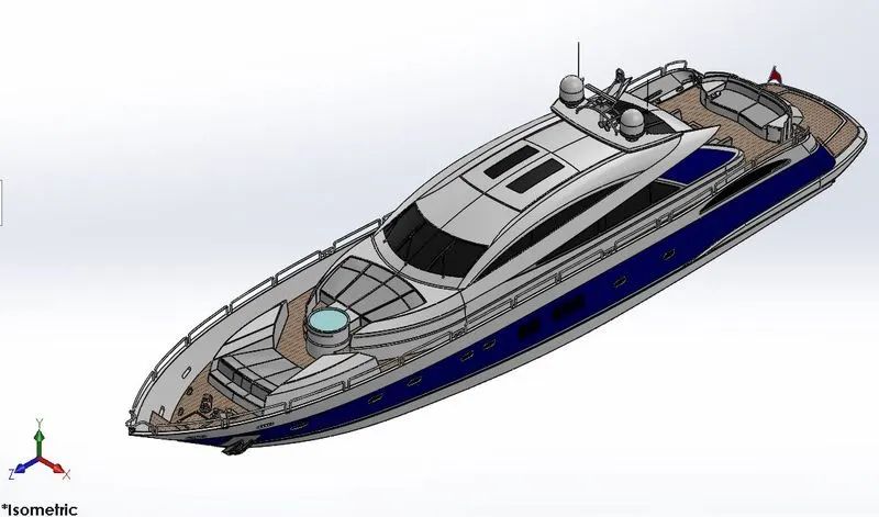
Isometric view:
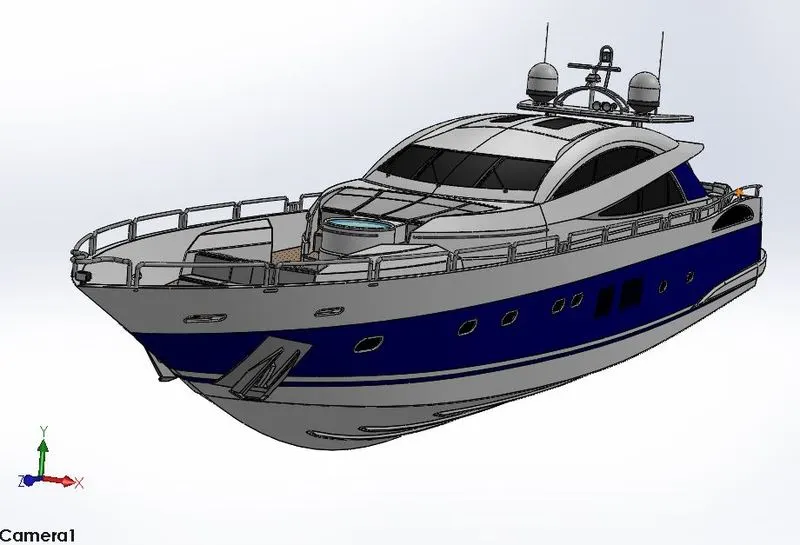
Camera View:
RENDERING OF AN SUNSEEKER PREDATOR YACHT
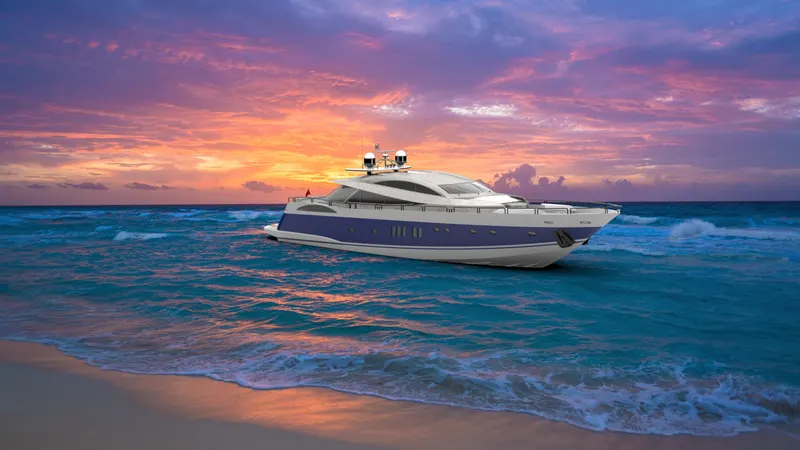
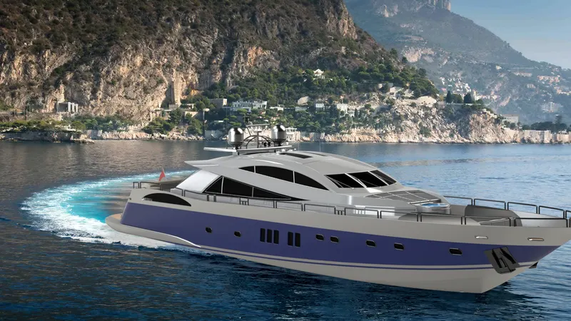
Rendering is a process of creating a realistic view images from the model.Rendering is mostly used in marine designs,automotive designs,vedio game designs,architecture designs etc and it helps us of creating a various effects of lighting,setting new environments and making high contrast images.In solidworks rendering can be obtained by using the photoview 360 and solidworks visualize.
Adding Decals:Decals are the decorative stickers,labels applied on the surfaces of the components and it is composed with paper backing of adhesive glossy finish layer.
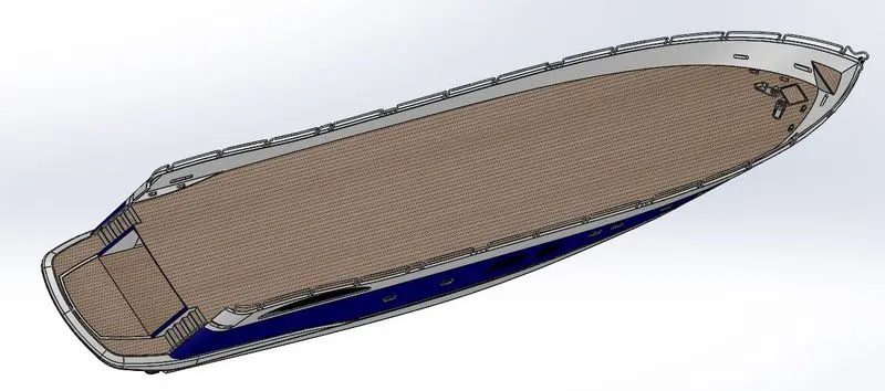
Decal on hull:
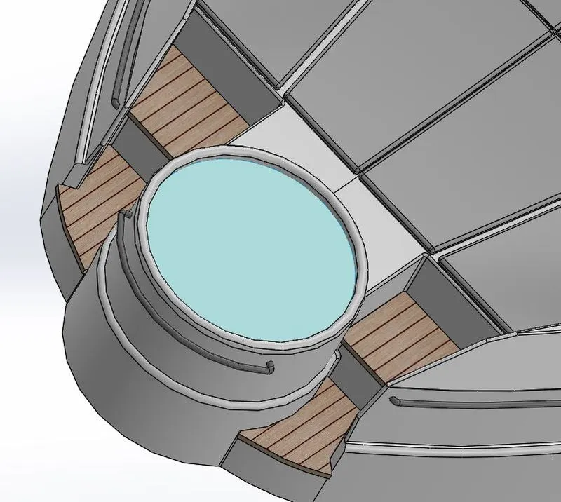
Decal on front steps of superstructure:
Adjusting colors and Editing materials:For applying the different colors to the different materials,we can edit the materials and create new display states and apply the colors as per the requirement.
Scene composition: In order to view the yacht model more realistic,changing the scene composition by turn on the perspective view.
Adding Lights and Cameras:By adding the lights we can adjust the direction,intensity and color of lights for creating realistic visual appearance and adding the cameras we can make the 3d model views as per the customize direction.
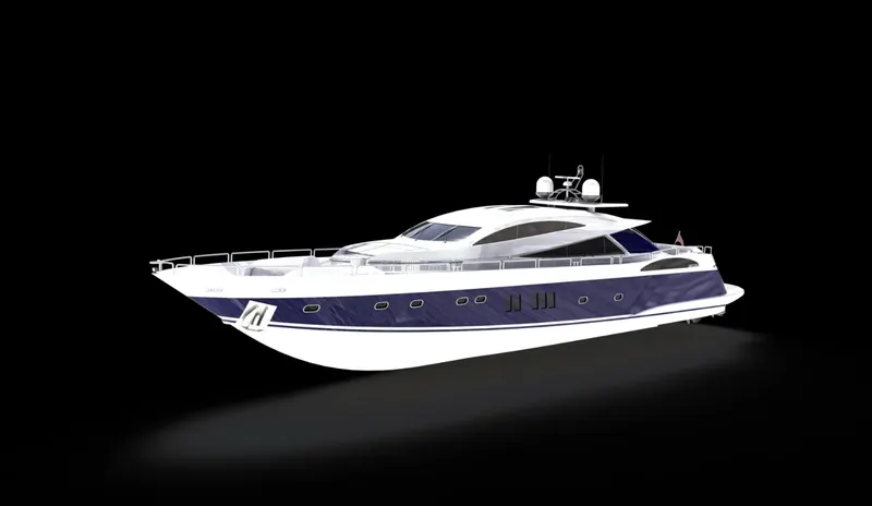
Rendering with PhotoView 360:
- Open model-Click tools-Add In-PhotoView 360.
- Edit the scene,appearances and environment.
- Finalise the render and create the schedule render.
Render image of photoview 360:
Rendering with Solidworks Visualize:
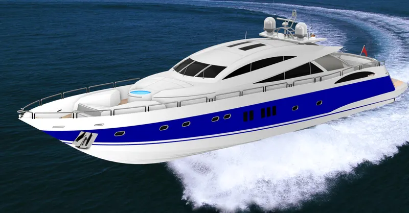
- Open solidworks visualise from start menu.
- Create the new project and import the model.
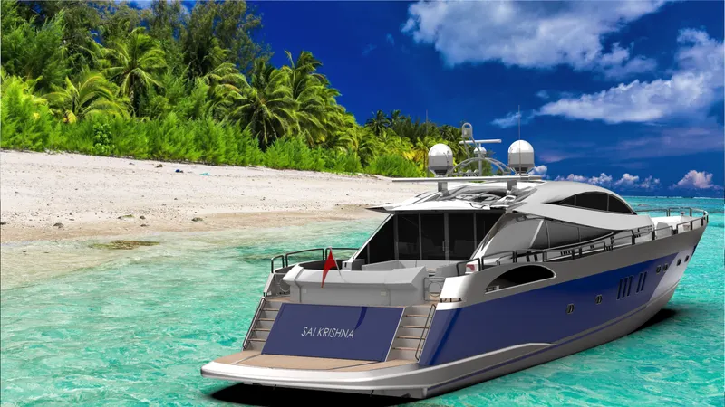
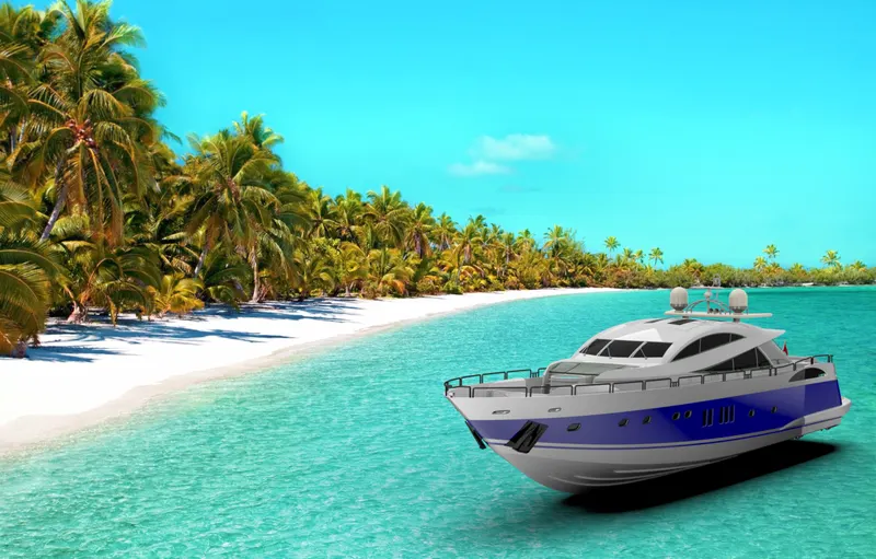
- Apply the appearnces,scenes and cameras.
- Preview and render it out.
Render images of Solidworks visualise:
Conclusion:
- Sketching and modelling of sunseeker predator parts by using with different solid and surface features can be learnt and also gain a practical knowledge on how to model the several components by using solidworks.
- Got a detailed information on how to assemble different components into single assembly file by using the mate relations and finally made the yacht model precisely.
- Gain a knowledge on how to apply decals,change scene composition,adding lights and cameras and how to generate the rendering by using photoview 360 and solidworks visualize.
THANK YOU