Photo Realistic Rendering
TITLE : DESIGN AND RENDERING OF AMERICAN CHOPPER BIKE BY USING SOLIDWORKS
Objective :To design and model the parts of American Chopper bike,enagaging those parts into one assembly without constraints and finalize that assembly with rendering in order to make the photo-realistic views by using solidwork tools.
Introduction : Solidworks is a computer-aided design software (CAD) and it was introduced by the Dassault systems for creating the models and assemblies.It consists of geometry tools which is essentially used for 2D sketching like lines,arcs,splines,circles,points and and also having the several relations which are used to define the attributes such as concentricity,coincident,parallelism,perpendicularity and also the assembly mates used for construction of assemblies without constraints.
So by using solidworks,to model the parts and assemble the American chopper bike and can make the photo-realistic rendering by using photoview 360 and solidworks visualize.
Design Methodlogy/Approach :
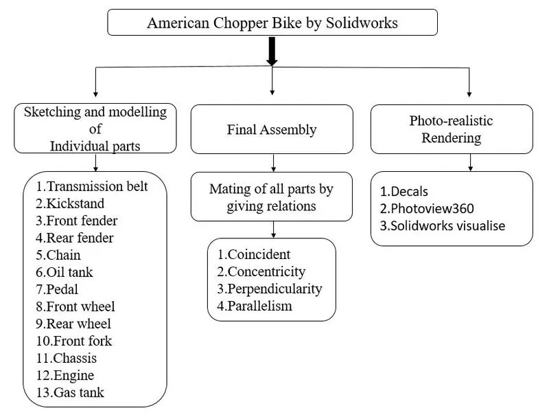
Modelling of Individual parts
1.Transmission belt:
A transmission belt is a device which is mainly used for transmitting the power from engine to gear box.
Features used for designing the Transmission belt:
- Sketch
- Offset Entities
- Extrude
- Fillet
- Appearance
Sketch: Sketch is a 2d drawing of the model and it having several entities like line,arc,spline,rectangle etc.
Offset Entities: Offset entities are used for making the copy of selected geometry such as splines,arcs,lines etc;with respect to the selected geometry in specified distance.Offset can be done in both forward and reverse directions.
Extrude: Extrude is one of the most unique feature used to convert the 2D sketch into 3D model.Extrude can be done in both forward and reverse directions.It can be extruded from up to vertex,up to surface,offset from surface and from midplane.
Fillet: Fillets are used for creating the rounded and smooth faces in both internal and external faces on the parts.Fillet can be done from all the edges of face,edges,loops etc.It is mainly used to avoid the hard and sharp edges.
Procedure to be followed:
- Firstly open a new solidworks part with MMGS unit system.
- Select a front plane and select the sketch.
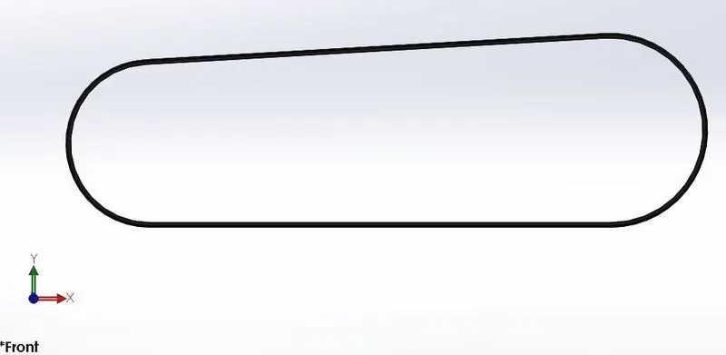
- Sketch the belt profile as per the required dimensions.
- After the sketch profile is created it is offset to a distance for creating the thickness of transmission belt.
- Once the sketch profile is completed without constraints and can exit from the sketch.
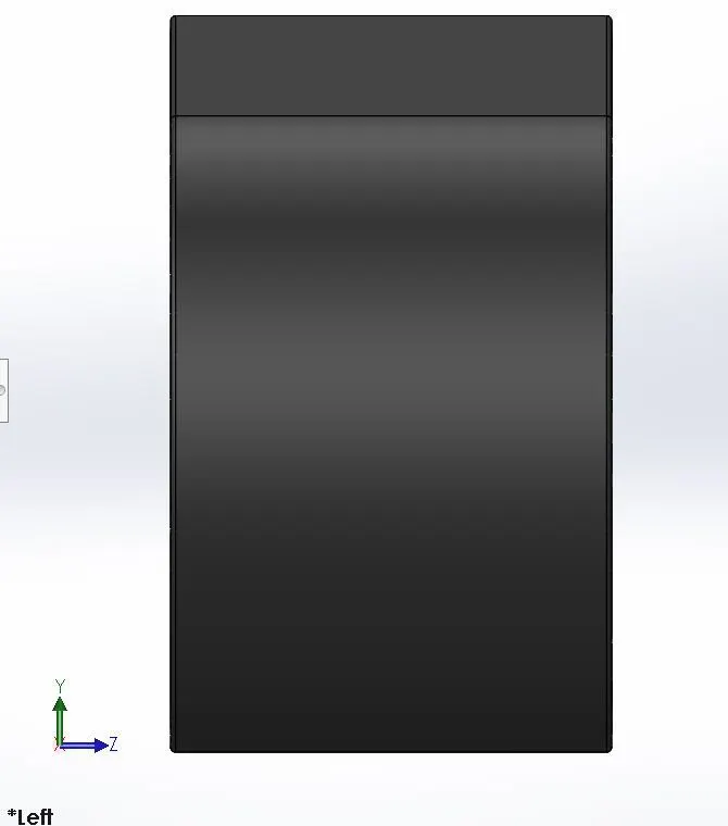
- Select the boss extrude and extrude that profile with 88 mm dimension.
- Once the extrude is completed,select the fillet and apply the fillet of 1 mm to the edges to avoid the sharp edges.
- After the model is completed,apply the appearance(Matte rubber).
- Finally save the part model as "Transmission Belt".
Views of Transmission belt:
Front view:
Left view :
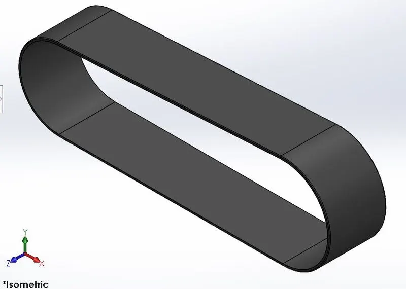
Isometric view:
2.Kickstand:
A Kickstand is a side stand for the bike mainly used for providing support to the bike when it is in idle condition.
Features used for designing the Kickstand:
- Sketch
- Loft
- Dome
- Extrude
- Extrude cut
- Fillet
- Split
- Appearance
Loft: Loft creates a feature by making the transitions between multiple profiles and guide curves.It can creates feature only by taking the first,last profiles as a points.All the entities like profiles,guide curves can be taken in single 3d sketch.
Dome: Dome is a half-sphere shaped structure and it is applied to the planar and non planar faces for creating a sphere shape faces.
Extrude cut: Extrude cut is similar as extrude boss but only the difference is extrude cut will removes the material from the extruded boss surfaces.Extrude cut can be done in both forward and reverse directions and it can helps us of creating a complex holes,slots etc.
Split: Split tool is mainly used for projecting the entities on the other planar or curved faces and it can also split the faces on multiple bodies with single command.
Procedure to be followed:
- Firstly open a new solidworks part with MMGS unit system.
- Before creating the sketch,rename the planes as per the model convenience.
Front plane-Front plane
Top plane-Top plane
Right plane-Mid plane
- Select the midplane and select sketch.
- Draw the ellipse as per the dimension and select the right plane and view normal to.
- After selecting the right plane,select the spline for representing the kickstand curvature.
- Take the new plane from reference geometry tools at the end of spline for representing the other end body of kickstand.
- Draw an ellipse at the end of spline which makes the complete profile for kickstand and it is fully defined.
- Select the loft boss for creating a loft to the kickstand profile.
- Once the loft body is created,select the dome and apply at the two end faces of the body.
- Sketch the rectangle at big end face for making a cut to pivot the stand for chopper.
- Select the extrude cut and remove the unnecessary part.
- Sketch the construction line at the small end face for creating the flat surface which touches the ground and select split command and remove the part of stand body below the line.
- Select the extrude option and extrude at both sides at a extrude cut region.
- Fillets are added at cut region in order to remove the sharp edges.
- After the model is completed, apply the appearnce(Chromium plate).
- Finally save the part model as "Kickstand".
Views of Kickstand:
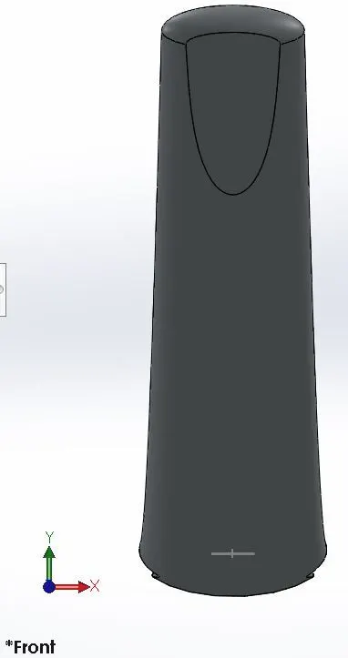
Front view:
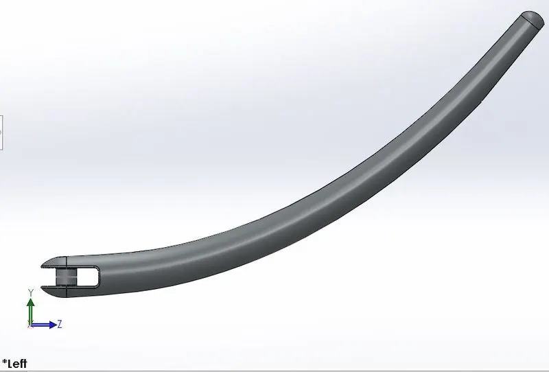
Left view:
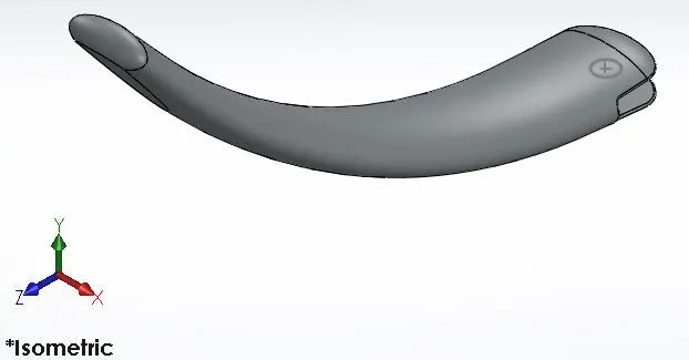
Isometric view:
3.Front Fender:
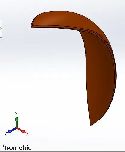
Front fender is mounted on the front fork and on the above of front wheel.The main purpose of front wheel is to provide protection for riders as well as other front parts of vehicle from the sand particles,dust,liquids and other spray particles on the road while vehicle in the motion.
Features used for designing the Front Fender:
- Sketch
- Offset Entities
- Trim Entities
- Extend Entities
- Revolve
- Appearnce
- Dynamic Mirror
- Split
- Fillet
- Shell
Trim Entities: Trim entities are used for removing the unwanted portions or parts from the design 2D sketch.Trim can be only applied when the sketch parts are must coincident with other parts.If the trim is not selecting at the edges or curves,make sure you convert them into convert entities and apply the trim feature.
Extend Entities: Extend Entities are used to extend the lines,arcs which adds a length from one sketch entitity to another sketch entity.
Revolve: It is used for revolving the profiles and it can takes the centerline or edges as reference axis in which to revolve around that axis.During revovle ,the centerline or edges are unable to revolve we can turn on the view temporary axis and can use it as reference axis to revolve around that.
Dynamic Mirror: It is used to mirror the selected sketch and shapes along with the original profile.
Shell: Shell feature is used for defining the thickness of thick and thin elements.
Procedure to be followed:
- Firstly open a new solidworks part with MMGS unit system.
- Before creating the sketch,rename the planes as per the model convenience.
Front plane-Vertical plane front fender
Top plane-centre plane front fender
Right plane-Mid plane front fender
- Select the vertical plane front fender and select sketch.
- Select the 3-point arc and complete the profile as per the required dimensions.
- Select the offset entities and offset the profile in order to maintain the thickness for fender.
- Select the trim and trim unwanted portion and extend entities used to extend from main sketch to offset sketch.
- After sketch is completed with fully defined and exit from the sketch.
- Turn on temporary axis and select revolve option to revolve the profile by selecting temporary axis as reference axis to revolve around that for completing fender model.
- After that appearnce is added to that model(Sienna).
- sketch the line for creating a geometric cut at the ends of fender body and this line is used for dynamic mirror.
- Next a spline is created as per required dimensions.
- Split tool is used to cut the part and complete the model.
- Fillet is added to edges and outer face of the fender for rounded off edges.
- For creating a shell inside the fender,select the shell and make internal shell for fender.
- Finally save the part model as "Front Fender".
Views of Front Fender:
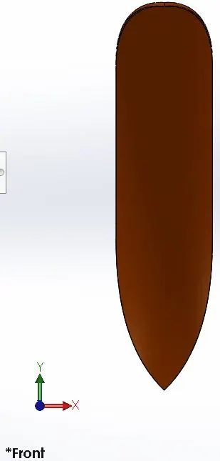
Front view:
Left view:
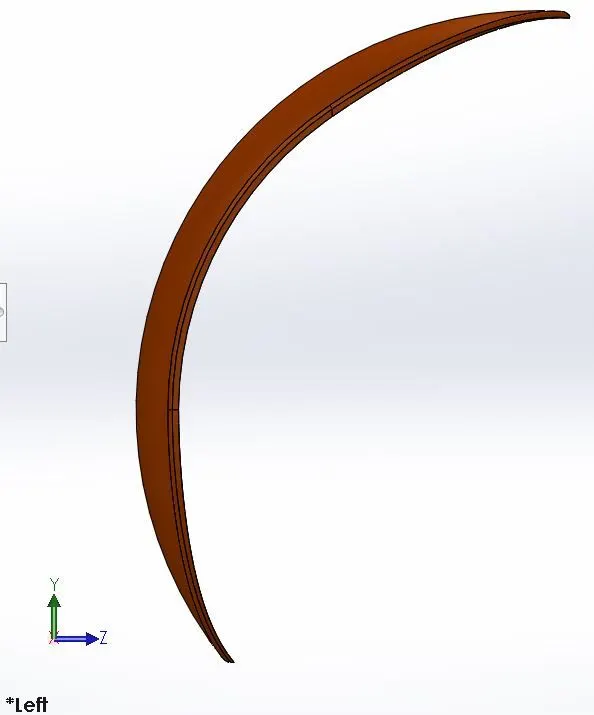
Isometric view:
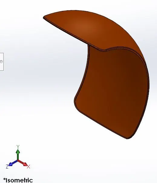
4.Rear Fender:
A rear fender is similar as the front fender but it is mounted on chassis and on the above of rear wheel.It also protects the rider and other rear parts from falling of dust particles,sand particles and other spray particles while the vechicle is in motion.
Features used for designing the Rear Fender:
- Sketch
- Offset Entities
- Trim Entities
- Revolve
- Appearnce
- Split
- Fillet
- Shell
Procedure to be followed:
- Firstly open a new solidworks part with MMGS unit system.
- Before creating the sketch,rename the planes as per the model convenience.
Front plane-Vertical plane front fender
Top plane-centre plane front fender
Right plane-Mid plane front fender
- Select the vertical plane front fender and select sketch.
- Select the 3-point arc and complete the profile as per the required dimensions.
- Select the offset entities and offset the profile in order to maintain the thickness for fender.
- Select the trim and trim unwanted portion and extend entities used to extend from main sketch to offset sketch.
- After sketch is completed with fully defined and exit from the sketch.
- Turn on temporary axis and select revolve option to revolve the profile by selecting temporary axis as reference axis to revolve around that for completing fender model.
- After that appearnce is added to that model(Sienna).
- Select arc and sketch for creating a geometric cut on the ends of fender body.
- Split tool is used to cut the part and complete the model.
- Fillet is added to edges and outer face of the fender for rounded off edges.
- For creating a shell inside the fender,select the shell and make internal shell for fender.
- Finally save the part model as "Rear Fender".
Views of Rear Fender:
Front view:
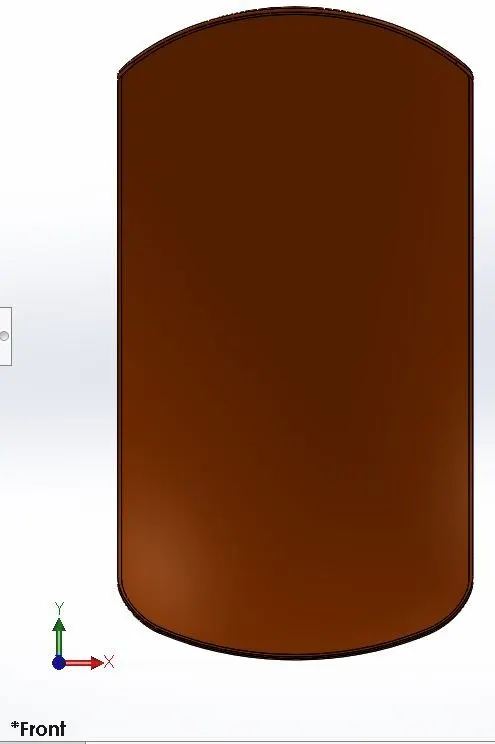
Left view:
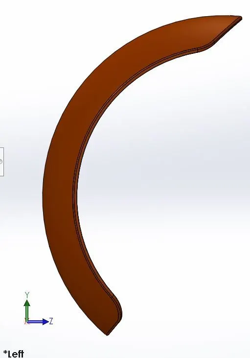
Isometric view:
5.Chain:
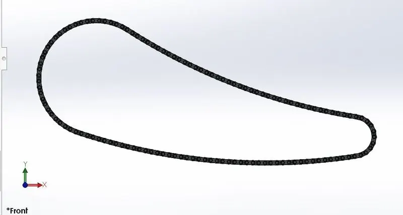
Chain is a power transmitting device used to transmit the power from engine to the rear wheel.At the engine side it is mounted on the small sprocket and at the rear wheel it is mounted on big sprocket.The sprocket is connected with the help of shaft.
Features used for designing the chain:
- Sketch
- Fillet
- Blocks
- Extrude
- Curve drive pattern
- Mirror Entities
- Appearnce
Blocks: Blocks are used for grouping the lot of objects together.They provide a great way of dealing with imported geometry,especially when you having a lot of objects and also provide the ability to perform conceptual type design.
Curve drive pattern: Curve drive pattern is mainly used for creating a pattern along a linear or non linear paths.For creating a chain, curve drive pattern plays a major role.
Procedure to be followed:
- Firstly open a new solidworks part with MMGS unit system.
- Before creating the sketch,rename the planes as per the model convenience.
Front plane-Midplane chain
Top plane-centrplane chain
Right plane-Front plane chain
- Select the midplane chain and sketch and complete the chain path profile with fully defined.
- On the same plane at the top,make the sketch of chain plate 1 and chain plate 2 and also use straight slot for offset.
- Make the chain plate 1 and chain plate2 as blocks(Right click on chain plate profiles and convert them into blocks and can save it).
- After that the chain plates is inserted onto the chain profile by giving the relations like concentricity and coincident.
- Once the blocks are inserted, extrude the one side body of chain plates and pins.
- After extrude, fillet can be applied at edges for avoiding sharp edges.
- As the links created ,select that links and pattern is created till the next arc appears.
- After that repeat same procedure upto the total profile is completed.
- Once profile is completed,there is a misalignment in the last chain plate and select that chain plate and extrude by taking pins as reference.
- As the total profile is completed on the one side and other side is also completed by using the Mirror entities and complete the model.
- After the model is completed,apply the appearnce(polished steel).
- Finally save the part model as "Chain".
Views of chain:
Front view:
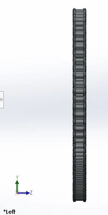
Left view:
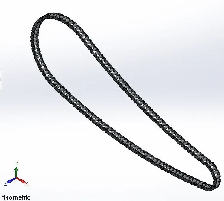
Isometric view:
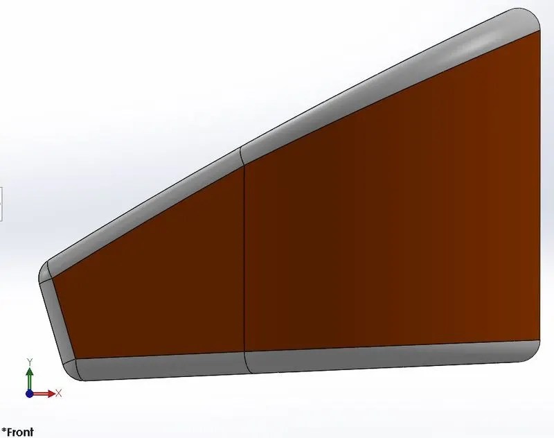
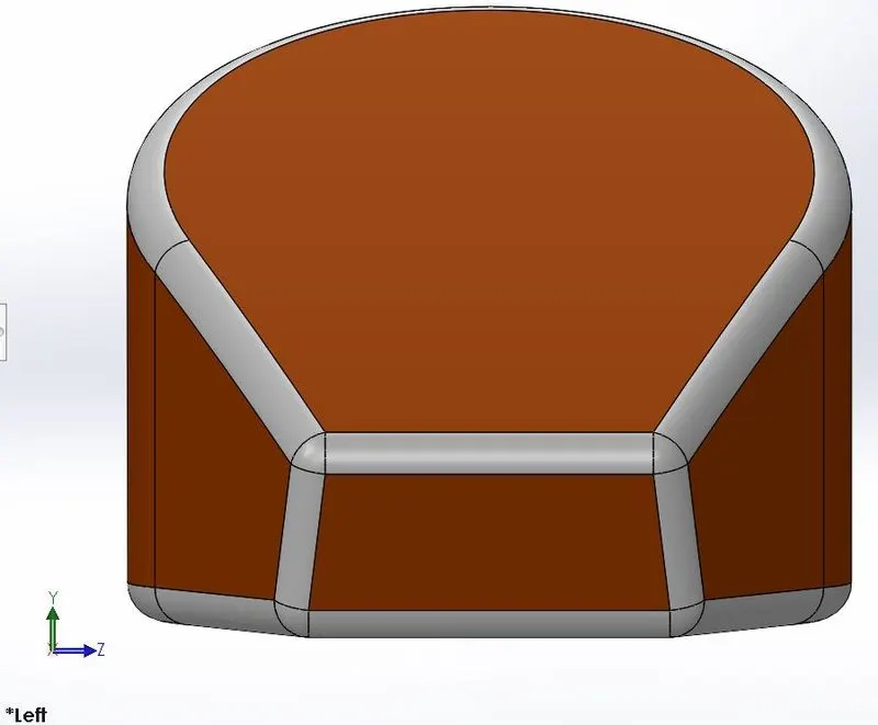
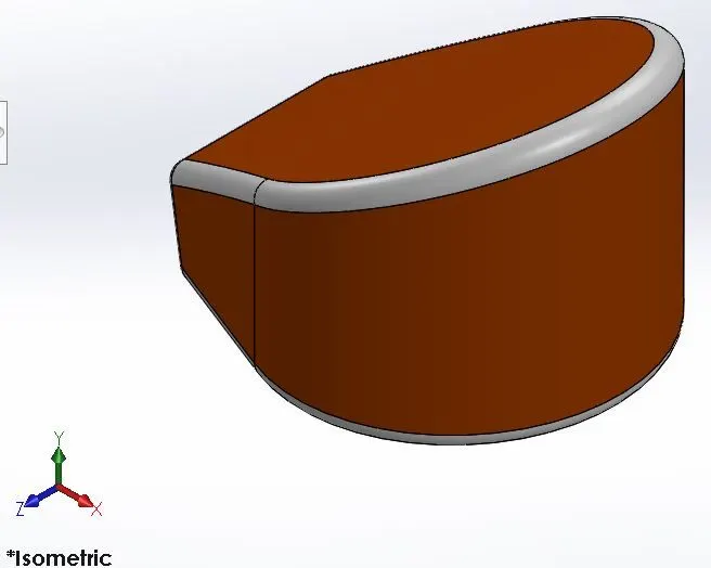
6.Oil Tank:
Oil tank is used for the storage of fuel which is required to run the engine and inside it is in the form of hollow shape.
Features used for designing the Oil tank:
- Sketch
- Extrude
- Combine
- Fillet
- Appearnce
- Shell
Combine: Comine features are used to combine the selected bodies as a single body by adding or substracting.
Procedure to be followed:
- Firstly open a new solidworks part with MMGS unit system.
- Before creating the sketch,rename the planes as per the model convenience.
Front plane-Midplane oil tank
Top plane-Top plane
Right plane-Right plane
- Select the midplane oil tank and sketch and profile as per dimensions with fully defined.
- Exit from the sketch and extrude that profile as per dimensions.
- Select a midplane oil tank and sketch and create sketch for shape profile from the side and extrude that.
- select combine entities and combine the selected bodies for required tank profile.
- Now the fillet is applied at the tank edges for creating rounded off edges.
- Appearance is applied(Sienna).
- Select the shell feature and apply for it to create hollow tank from solid body and also see that hollow with the help of sectional view and complete the model.
- Finally save the part model as "Oil Tank".
Views of Oil Tank:
Front view:
Left view:
Isometric view:
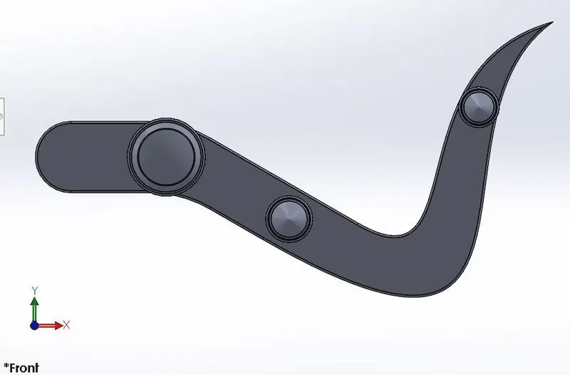
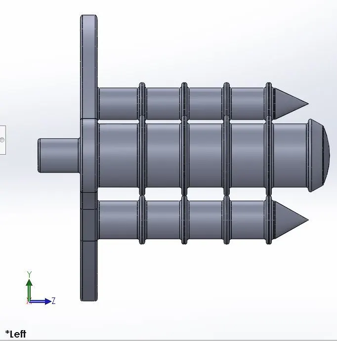
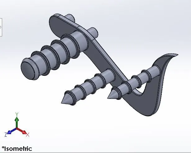
7.Pedal:
Pedals are used to place the legs of the rider for feeling comfort while the vehicle is in the motion.
Features used for designing the Pedal:
- Sketch
- Extrude
- Fillet
- Revolve
- Dome
- Chamfer
- Linear pattern
Chamfer:Chamfer is used for creating a sloping surfaces at the edge or corner on the selected body.
Linear pattern: Linear pattern is used for creating a pattern along a linear path.
Procedure to be followed:
- Firstly open a new solidworks part with MMGS unit system.
- Select a front plane and sketch and complete pedal profile.
- Select the extrude and extrude the selected profile as per the dimensions.
- Fillet the edges as per the dimensions.
- Select the top plane and sketch and profile is created for making the addditional peg with fully defined.
- Exit from the sketch and revolve the selected profile.
- Apply the dome feature for sphere shaped structure at the end of peg and fillet is also applied at the edges for making rounded off edges.
- Repeat the same procecdure for additional pegs but instaed of dome,chamfer is used for creating the sloping surfaces.
- After that the outer profiles of extruded pegs are offset and extrude and then multiplied by using linear pattern.
- Fillet is applied at all edges and complete the model.
- Finally save the part model as "Pedal".
Views of Pedal:
Front view:
Left view:
Isometric view:
8.Front Wheel:
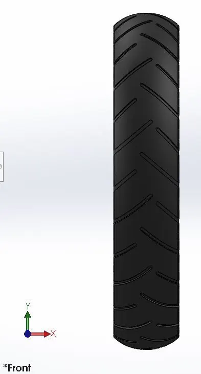
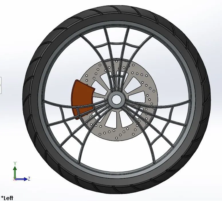
Front wheel is used for providing the motion to the bike and it is rotated by the force exerted from the driven pulley.Front wheel consists of several components.A Rim is the main skeleton of front wheel and tyre is mounted on the top of rim.Also the rotor is mounted on the side of rim and on the rotor the caliper is side mounted.It is attached to the end of fork with the help of shaft.
Features used for designing the Front Wheel:
- Sketch
- Revolve
- Trim
- Extrude
- Extrude cut
- Circular pattern
- Revolve cut
- Combine
- Fillet
- Chamfer
Circular pattern:Circular pattern is used for creating a pattern along the circular path.
Revolve cut:Revolve cut is used for removing the unwanted portion or part from the revolved model.
Procedure to be followed:
- Firstly open a new solidworks part with MMGS unit system.
- Select the front plane and sketch and draw the rim profile with fully defined.
- Select the revolve feature and revolve the rim profile.
- select the right plane and sketch and draw the web profile by taking the splines.
- Exit from sketch and extrude web profile.
- Select the extrude face and sketch and make the offset of spline edges for thickness.
- Trim the unwanted entities from the profile.
- Exit from sketch and with extrude cut remove the unwanted material from web body.
- Select the right plane and sketch and sketch the profile for inner sub webs.
- Extrude the inner sub webs.
- After the web is completed,select the circular pattern and pattern the web around the rim and combine them by using combine feature as a single body.
- Select the right plane and sketch and offset from the rim profile for creating rotor.
- Once the rotor profile is completed and extrude with small thickness.
- select the rotor face and sketch and draw the small holes and cutout profile on the rim.
- with extrude cut ,extrude small holes and cutout.
- Fillet is applied to the cutout.
- select circular pattern and pattern the holes and cutout around the rotor.
- A circle is drawn at the rotor centre and extruded to create a hole at the centre both rim and rotor.
- After rotor is modelled a sketch is drawn on rotor face for caliper.
- Extrude caliper profile from both directions.
- Apply the fillets and chamfer at eedges of outside faces.
- Select the front plane and sketch profile is created for the tyre.
- Use the revolved base feature for revolve the tyre profile and tyre model is completed.
- Select the front palne and sketch is created for applying threads on the tyre.
- Extrude the thread profile as per the required dimensions
- Fillets are applied to threads for rounded off edges.
- select the circular pattern and pattern the threads around the tyre.
- Apply the appearances for tyre(Matte rubber),Rim(Chromium plate),rotor(Carbon steel),caliper(sienna).
- Finally save the part model as "Front Wheel".
Views of Front Wheel:
Front view:
Left view:
Isometric view:
9.Rear Wheel:
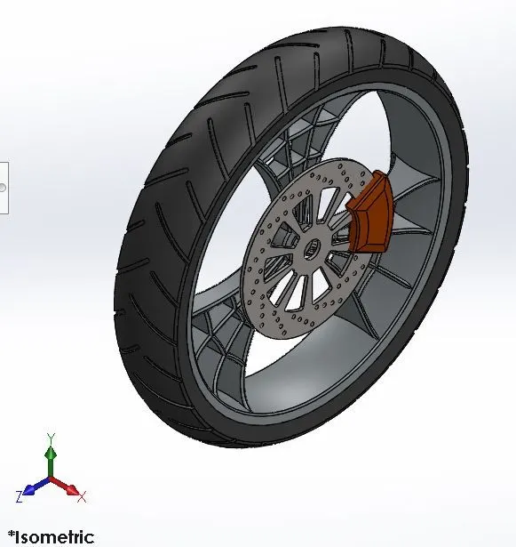
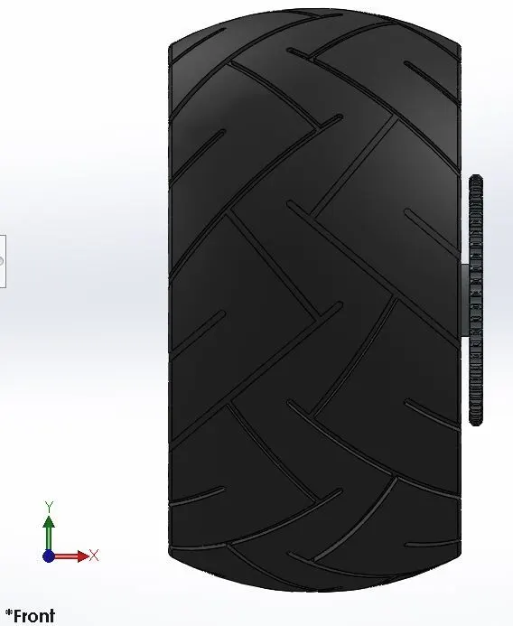
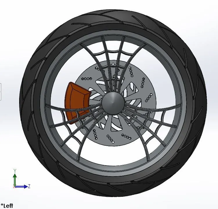
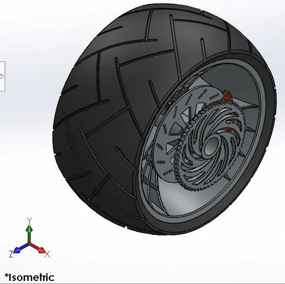
Rear wheel is similar as a front wheel except some addtional components mounted on it.It consists of sprocket for mounting of transmission chain.Rear wheel can be rotated when the transmission chain turns around from engine sprocket to rear wheel sprocket.
Features used for designing the Rear Wheel:
- Sketch
- Revolve
- Trim
- Extrude
- Extrude cut
- Circular pattern
- Revolve cut
- Combine
- Fillet
- Chamfer
Procedure to be followed:
- Firstly open a new solidworks part with MMGS unit system.
- Select the front plane and sketch and draw the rim profile with fully defined.
- Select the revolve feature and revolve the rim profile.
- select the right plane and sketch and draw the web profile by taking the splines.
- Exit from the sketch and extrude web profile.
- Select the extrude face and sketch and make the offset of spline edges for thickness.
- Trim the unwanted entities from the profile.
- Exit from sketch and with extrude cut remove the unwanted material from web body.
- Select the right plane and sketch and sketch the profile for inner sub webs.
- Extrude the inner sub webs.
- After the web is completed,select the circular pattern and pattern the web around the rim and combine them by using combine feature as a single body.
- Select the right plane and sketch for the additional parts to be removed.
- use the revolve cut to remove the part and fillet is added to inner and outer faces
- For creating a hole at hub part use the extrude cut option and make hole as per dimension.
- Similarly axle for the wheel is created and take the sketch on that face for create the rotor profile.
- Rotor profile can be extruded and on that face select the sketch for making the small holes.
- Make the holes profile and extrude cut option is used for remove the material.
- Apply the circular pattern for creating th holes throughout the rotor.
- Select rotor face and sketch and create the cutout profile.
- With extrude cut remove the cut out and apply the fillet
- Circular pattern is used for create cutout throughout the rotor.
- Select the rotor face and sketch and create the caliper profile.
- Extrude option of offset will be used for making the caliper on both sides.
- Apply the chamfers on the both faces and fillet is also applied on the edges.
- Select rotor face and sketch and create the profile for sprocket.
- With extrude option,extrude the sprocket profile with offset.
- Select the sprocket face and sketch for the teeth profile and extrude cut used for remove the material.
- Circular pattern is used to create the teeth all over the sprocket.
- select the sprocket face and sketch and create cut out profile on sprocket.
- Reove the material with extrude cut and circular pattern used for making the cut out from the sprocket.
- Select the front plane and sketch profile is created for the tyre.
- Use the revolved base feature for revolve the tyre profile and tyre model is completed.
- Select the front palne and sketch is created for applying threads on the tyre.
- Extrude the thread profile as per the required dimensions
- Fillets are applied to threads for rounded off edges.
- select the circular pattern and pattern the threads around the tyre.
- Apply the appearances for tyre(Matte rubber),Rim(Chromium plate),rotor(Carbon steel),caliper(sienna),sprocket(Chromium plate).
- Finally save the part model as "Rear Wheel".
Views of Rear Wheel:
Front view:
Left view:
Isometric view:
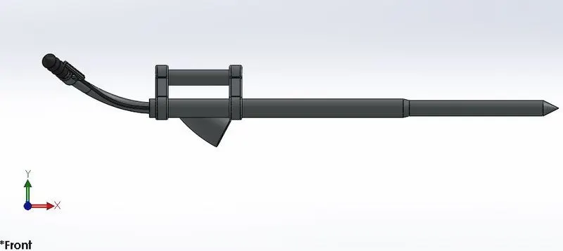
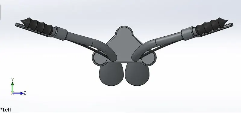
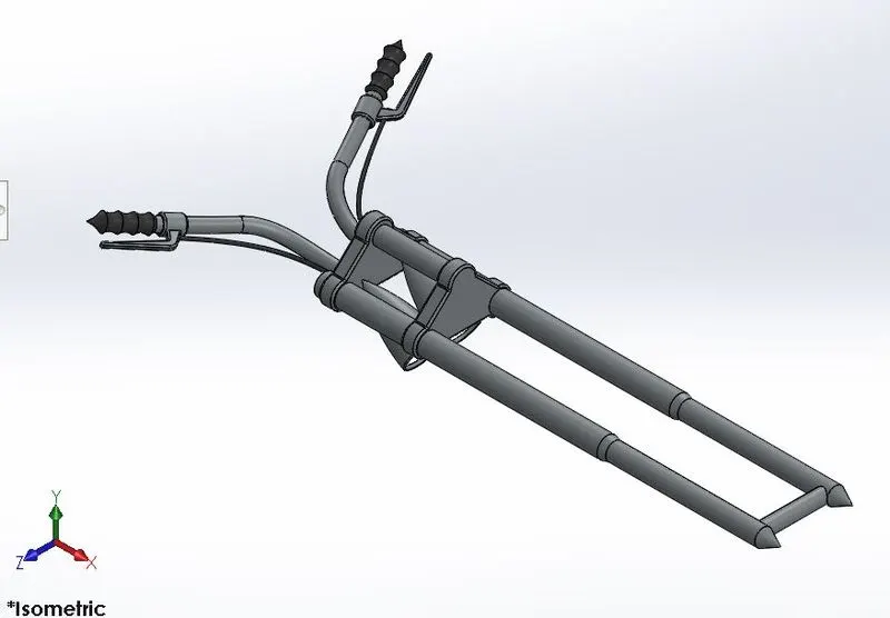
10.Front Fork:
Front fork is mainly used for steering purpose and suspension for the front wheel of the vehicle.It consists of major components like handle, accelerator, clutch, brake, head lights and several switches required for bike.on one side it is attached to top of the chassis end and lower portion is attached to front wheel which makes good suspension and absorb the vibrations of the body.
Features used for designing the Front fork:
- Sketch
- Revolve
- Extrude
- Fillet
- Trim
- Linear pattern
- Dome
- Body-Move/copy
- Revolve cut
- Project curve
- Sweep
- Mirror
- Combine
Project curve:This tool is used for converting the 2D curves into 3D curves and it is mostly used for sweeping the curves.
Sweep:Sweep is used of making the extrude body to the sweeping curves.
Procedure to be followed:
- Select the front plane and sketch and create the half sketch of fork tube.
- Exit from from sketch and revolve is used for making fork tube.
- Select the right plane and sketch and create profile for the triple clamps.
- Extrude the profile and required fillet is added.
- Use the linear pattern for creating two instances triple clamps on tube body.
- Select front plane and sketch for creating axle profile and extrude that profile.
- select right plane and sketch and create profile for extension of rod between two triple clamps and extrude that.
- After that sketch the headlight profile and revolve that profile.
- Use the body-move/copy to move the headlight to required position.
- Dome is used for creating the light shape and extrude cut is used for creating the cut edges.
- Two curves are made on two projection planes and projected curve used for create sketch for handle bar.
- Sweep the projected curve for handle body.
- After that sketch the handle profile and use the revolve option for revolve it.
- After Sketch is create for handle lever and extrude that.
- For creating the braking wire, sketch the curves with project curve option and sweep that curves.
- Once the fork body is created on one side,use the morror entities for creating the body on the other side.
- Once the model is completed,create the new reference plane in which the front plane is normal to new plane
- After that appearnces is applied for respective bodies.
- Finally save the part model as "Front Fork".
Views of Front Fork:
Front view:
Left view:
Isometric view:
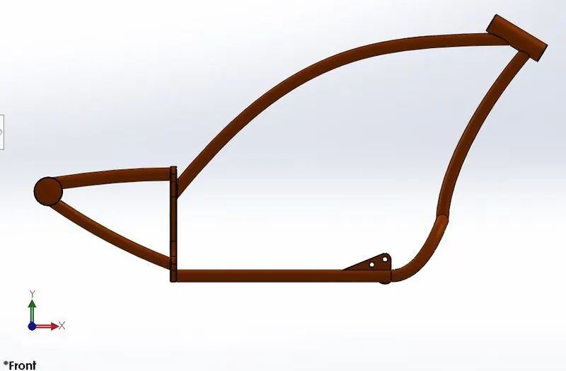
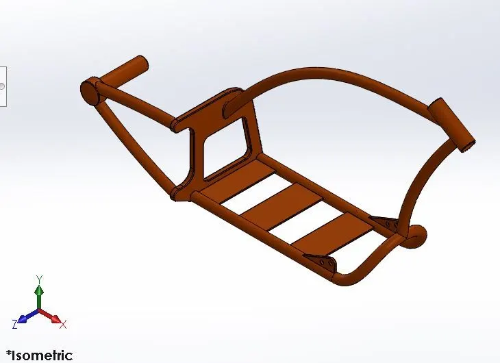
11.Chassis:
Chassis is also known as Frame.It is the main suppport structure and backbone for the vehicles whether it is two wheeler or four wheeler.It can withstand all the load of vehicle even in static as well as dynamic conditions.All the parts of vehicle body are majorly connected to the chassis.
Features used for designing the Chassis:
- Sketch
- Insert sketch picturte.
- Spline
- Offset Entities
- Trim
- Circle
- Convert Entities
- Projection of lines
- Revolve
- Extrude
- Projection of planes
- Combine
- Sweep
- Appearnce
Procedure to be followed:
- Firstly open a new solidworks part with MMGS unit system.
- Before creating the sketch,rename the planes as per the model convenience.
Front plane-Midplane Chassis
Top plane-Bottom plane Chassis
Right plane-Right plane
- Initially select the midplane chassis and insert the sketch picture and positioned which is used for reference.
- After that sketch the bottom profile of chassis in two planes to get a projected curve
- Use the project curve option in order to get 3D curve for chassis.
- Use the sweep option for cuve to create the chassis tube.
- Use the mirror option to make symmetry tube on other side.
- Create the sketch for rear part of chassis and extrude is performed as per the dimensions.
- Create the cutout sketch on that and remove that portion by using the extrude cut.
- Create the sketch for extension of chassis to axle and extrude that.
- After that create the curves and sweep that for tube sections.
- Create the new sketch for bottom mounting plates and extrude.
- Create the sketch for levers and extrude that with offset.
- Once the model is completed,hide the sketch picture.
- Apply the appearnce to the Chassis body.
- Finally save the part model as "Chassis".
Views of Chassis:
Front view:
Left view:
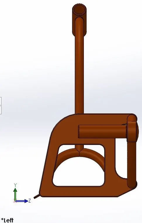
Isometric view:
12.Engine:
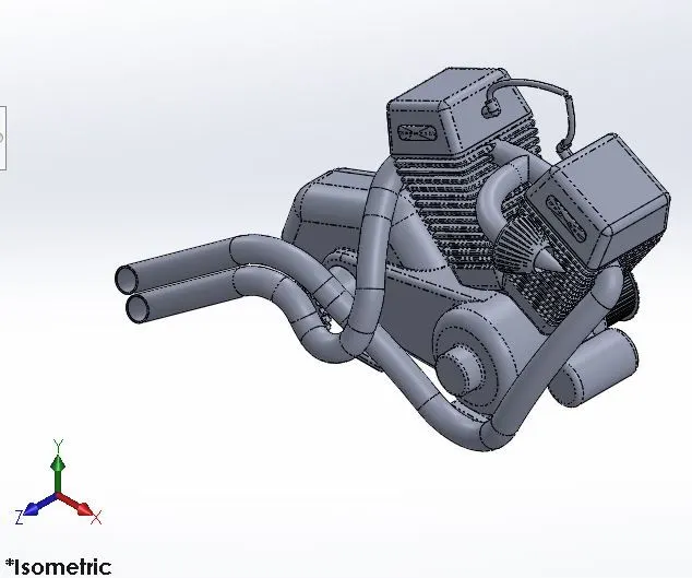
Engine the main heart for the vehicle.All the combustion process will takes place in the engine and it is used for converting the thermal energy into the mechanical energy which provides the motion to the vehicle.It consists of several components like cylinders,pistons,spark plugs,inlet and exhaust pipes etc.
Features used for designing the Engine:
- Sketch
- Sketch picture
- Extrude
- Fillet
- Revolve
- Circular pattern
- Dome
- Extrude-cut
- Chamfer
- Linear pattern
- Mirror
- Split
- Sweep
- Combine
- Project curve
- Composite curve
Composite curve: Composite curve feature is used to join the two curve profiles and make it as a single curve.
Sketch picture:This feature is used to insert the reference picture for the making the sketch easy.
Procedure to be followed:
- Firstly open a new solidworks part with MMGS unit system.
- Select the front plane and insert the sketch picture as in suitable position
- Select the front plane and sketch and create the profile for egine body and extrude that.
- Take the same plane and create the sketch for the transmission case and extrude as solid body and apply the fillet.
- Create a new plane for pulleys and sketch the pulley profiles and revolve that making solid bodies.
- Create the sketches on the pulleys for making the teeth profile on pulleys and extrude that.
- Use the circular pattern for making the teeth all over the pulleys.
- Create the sketch on the side of pulleys for making the holes and extrude cut is used to remove the material.
- Circular pattern is used to create holes around the pulley face.
- Dome option is used to create the dome on outer surfaces of pulleys.
- Apply the chamfer and fillet for the pulley.
- Create the new sketch for the engine block and extrude that body with required draft angle.
- Sketch the fin part and and use extrude cut to remove the unwanted areas..
- Use the linear pattern to create the fins along the engine head.
- Mirror that engine for making other identical engine.
- Create the sketch for small sprocket and extrude that and also make the teeth profile on sprocket and remove the the material by extrude cut.
- Use the circular pattern for making the teeth around the sprocket.
- Create the sketch for intake tube and sweep that profile and mirror option is used to create intake between two engine heads.
- After create the curves for exhaust pipe from engine head 1 and use the project curve to convert into 3D curve
- create a new reference plane at the end of projected curve and exhaust tube sketch is made.
- Make the curves composite by composite curve feature and sweep option is used for create the exhaust tube body.
- Similarly make the exhaust pipe for second cylinder.
- create sketch for inclined cut of exhaust pipes and use the split feature.
- After that create the sketches for spark plug wires and sweep option is used to make the body.
- Finally save the part model as"Engine".
Views of Engine:
Front view:
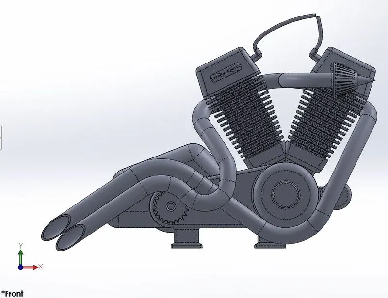
Left view:
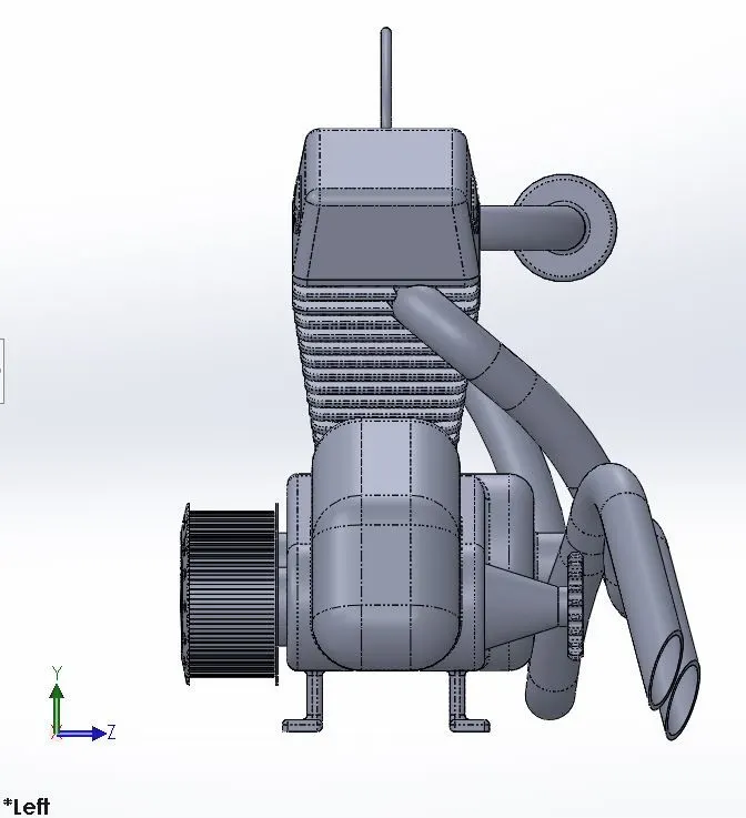
Isometric view:
13.Gas Tank:
A gas tank is used for holding the vast majority of gas for the fuel system.
Features used for designing the Gas Tank:
- Sketch
- sketch picture.
- Loft surface
- Swept surface
- Boundary surface
- Trim surface
- Knit surface.
Loft surface:This feature works with solids and surfaces which allows of filling a gap between the two curved surfaces.
Swept surface:Swept surface is used for creating a pierce relations between a guide curves and profile.
Boundary surface:This feature is used for creating a surfaces between the boundaries or edges.
Trim surface: This feature helps us of removing the material from the surfaces.
Knit surface:This feature is used for converting surfaces into solid by combining the two or more non intersecting sufaces together.
Procedure to be followed:
- Firstly open a new solidworks part with MMGS unit system.
- Before creating the sketch,rename the planes as per the model convenience.
Front plane-Midplane fuel tank
Top plane-Bottom plane fuel tank
Right plane-Front plane fuel tank
- Select the midplane fuel tank and sketch and select the sketch picture.
- Sketch the profiles for top portion of gas tank and take a new plane and with swept surface option sweep that profile for body.
- Create a new plane and sketch is created for remove the surface material by using the surface trim.
- Create the sketch for bottom of tank and sketch the curves and project curve option is used to project the curve.
- Create two curves for side profile and project the curves anduse the boundary surfaces.
- Once the half tank is modelled use the mirror option for other side.
- Create a sketch on bottom plane and split option is used to split the sketch on bottom plane to seat part of created sketch.
- Extrude is used for creating the seat of the chopper.
- After use the boundary surface option for the bottom of the tank.
- Use the lofted option to create the covering part of bottom towards rear side and use surface knit.
- Apply the fillets to the edges as per the dimensions.
- After that use the sweep cut for cutting the part out of tank for creating frame clearance.
- Use the shell option for creating a shell from the gas tank body.
- Apply the appearance to gas tank(sienna).
- Finally save the part model as "Gas Tank".
Views of Gas Tank:
Front view:
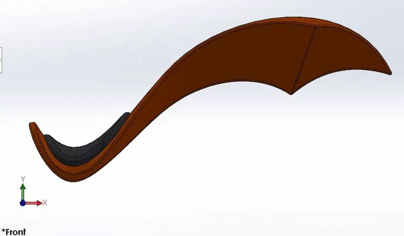
Left view:
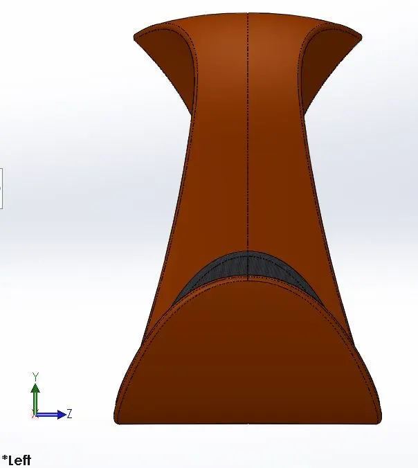
Isometric view:
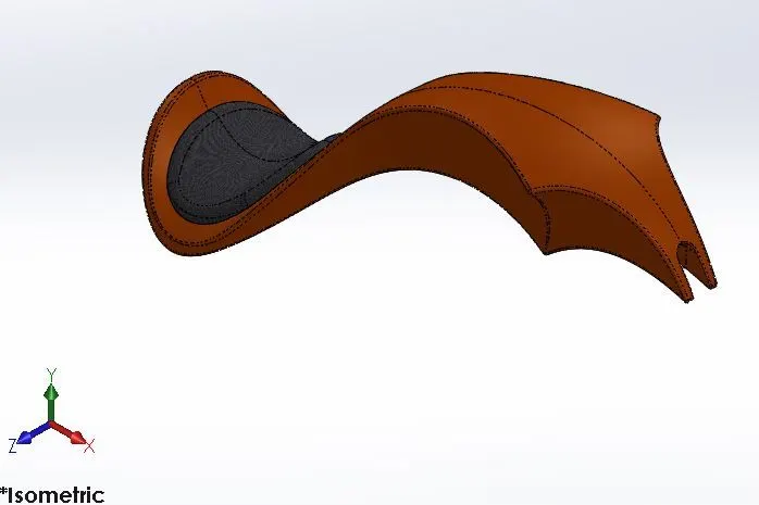
ASSEMBLY OF THE CHOPPER
Assembly is a process of inserting all the individual part model components into single part file.In solidworks assembly can be done by using the different mates.
Features used for making the assembly:
- Insert component.
- Mate
- Mirror component
- Edit component
Insert components: This feature is used for recalling the each individual part file during the assembly.
Mate:Mate is the most important feature used in the solidworks during the assembly, because it creates the geometric relations between assembly components.commonly used relations are:
- Coincident
- Concentricity
- Angle mate
- Width mate
- Parallel mate.
Mirror component:This feature is used for providing the identical components along with the original component.In chopper assembly, this feature is used for mirroring the foot pedal.
Edit components:This feature is used for editing the parts models within the assembly interface.It helps us for changing the dimensions of model whether there is any misalignment or intersecting the components with other.During chopper assembly, the chain can be intersected with chassis at the rear side.so its need to be modified and edit component is used for changing the dimensions.
Procedure to be followed for assembly:
- Initially select all the part models and open it.
- After that open the solidworks and select the assembly file template and then assembly interface will be opened.
- Firstly load the chassis with help of insert components and positioned.
- Next insert the engine and coincident its plane with the chassis and positioned by using mate.
- Next insert the pedal and positioned at required positon by using the mate.
- Then after mirror the pedal for the other side by using the mirror component.
- Next insert the kickstand and positioned and angle mate relation is applied for sliding the kickstand.
- Next transmission belt is inserted and positioned with mates.
- Next oil tank is inserted at top of transmission block and make coincident with midplane chassis.
- Next insert the rear wheel and its axle is make concentric with hub and apply other mates.
- Next insert the rear fender and is positioned at the top of rear wheel by using required mates.
- Next insert the chain and width mate,concentric is apllied for sprocket and parallel with bottom plane of chassis.
- Next insert the gas tank and apply the suitable mate conditions.
- Insert the front fork and positioned and angle mate with limit angle is applied for the rotation of fork.
- After that insert the front wheel and make concentric with fork end and hub and apply other suitable mates.
- Insert the front fender and make coincident with required palne of chassis and apply other mates.
- During inserting of chain,the chain is intersected with rear end end of chassis and can be edit its dimensions by using the edit component.
- Finally the chopper assembly can be completed.
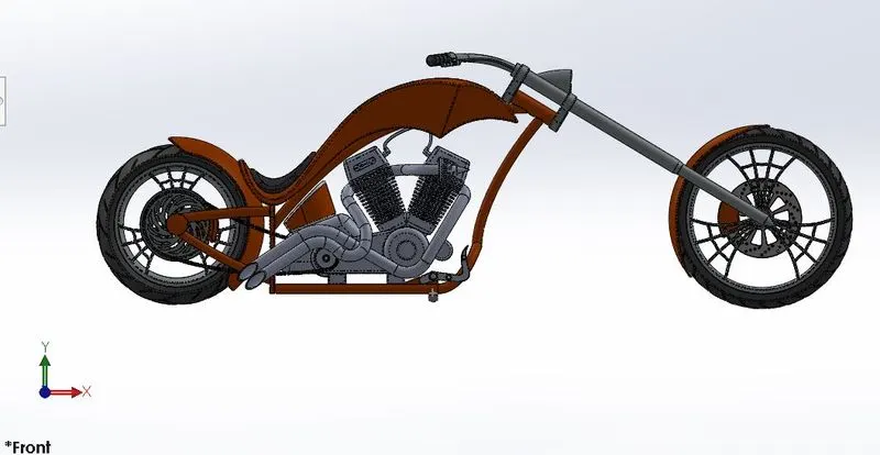
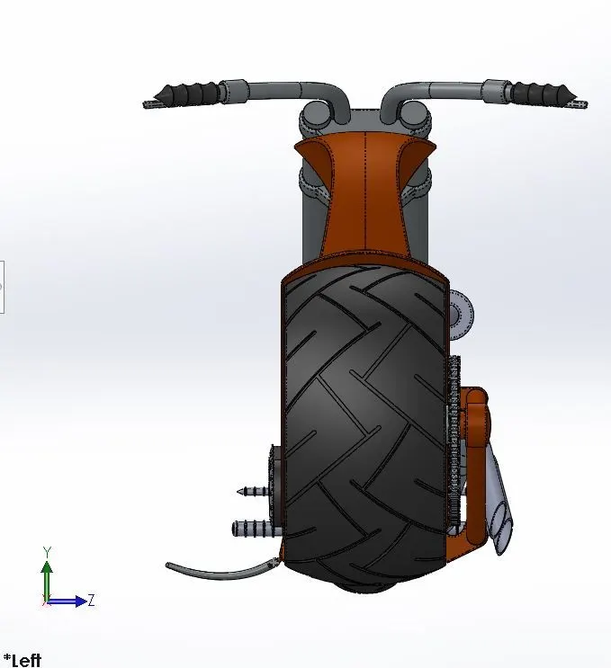
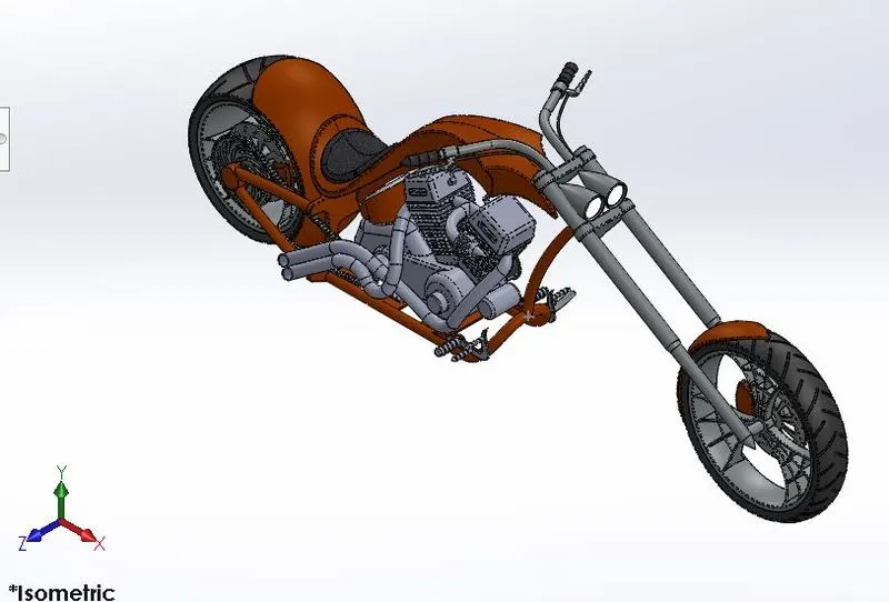
Views of American chopper assembly:
Front view:
Left view:
Isometric view:
Rendering of American Chopper Bike
Rendering is a process of creating a realistic view images from the model.Rendering is mostly used in automobile designs,vedio game designs,architecture designs etc and it helps us of creating a various effects of lighting,setting new environments and making high contrast images.In solidworks rendering can be obtained by using the photoview 360 and solidworks visualize.
Rendering setting for the chopper in environment: Rendering set up of chopper in environment is the major work before doing the real time rendering.
Attachment with the ground:For setting the chopper in environment, initially make the front wheel and rear wheel can be touch with the ground.After that rotate the handle bar to the left side for realistic view and then after make the stand to be touch with the ground.During stand alignment to ground,the length of stand will be more.so reduce that length for proper toching to the ground.
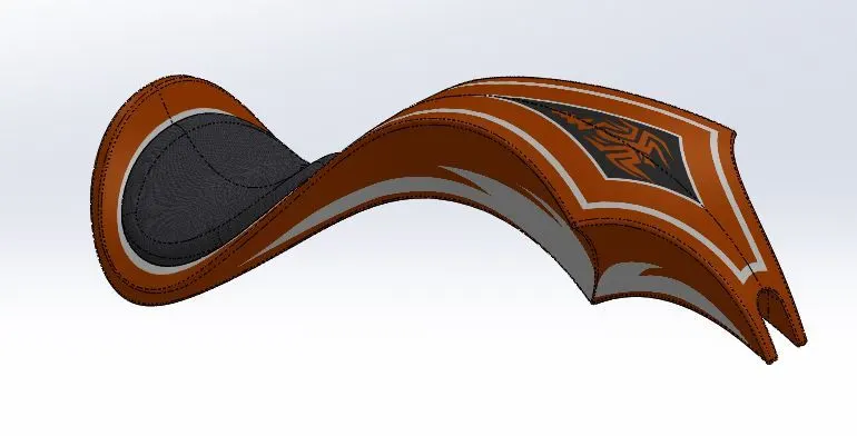
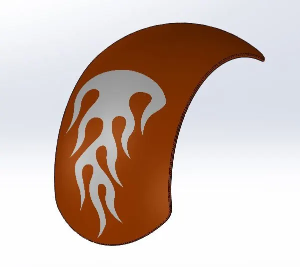
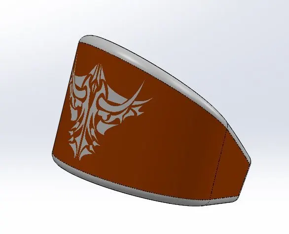
Applying decals to Gas tank,Rear fender and Oil tank:Decals are the decorative stickers,labels applied on the surfaces of the components and it is composed with paper backing with adhesive glossy finish layer.On the chopper,the decals are applied to Gas tank,Rear fender,Oil tank.
Decal on Gas tank:
Decal on Rear fender:
Decal on Oil tank:
Adjusting colors and Editing materials:For applying the different colors to the different materials,we can edit the materials and create new display states and apply the colors as per the requirement.
Scene composition: In order to view the chopper model more realistic,changing the scene composition by turn on the perspective view.
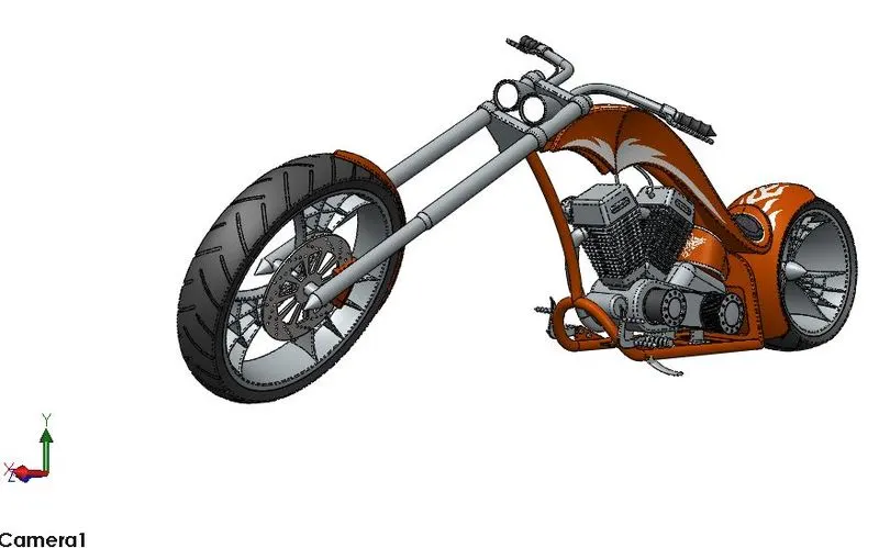
Adding Lights and Cameras:By adding the lights we can adjust the direction,intensity and color of lights for creating realistic visual appearance and adding the cameras we can make the 3d model views as per the customize direction.
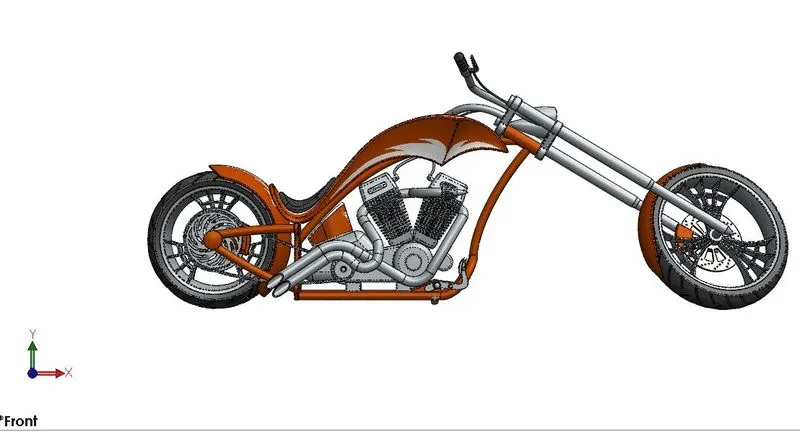
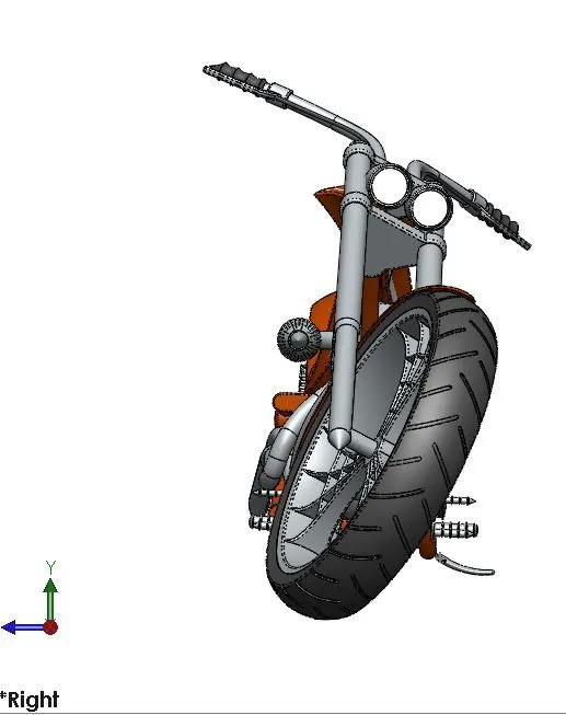
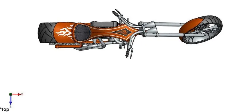
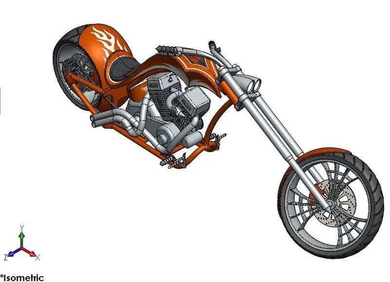
View of the chopper assembly after setting up in the environment:
Front view:
Right view:
Top view:
Isometric view:
Camera set up view:
Rendering with PhotoView 360:
- Open model-Click tools-Add In-PhotoView 360.
- Edit the scene,appearances and environment.
- Finalise the render and create the schedule render.
Scene and the environment use for the chopper:
Scene-White kitchen.
Environment-Day time.
Rendering images of photoview 360:
Front of chopper view:
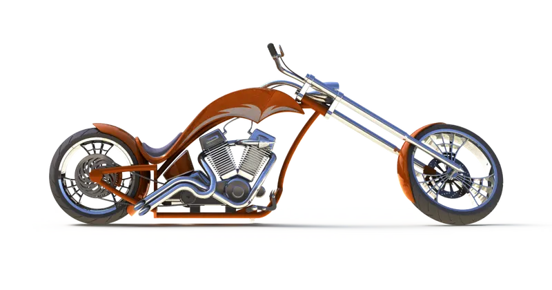
Camera set up view:
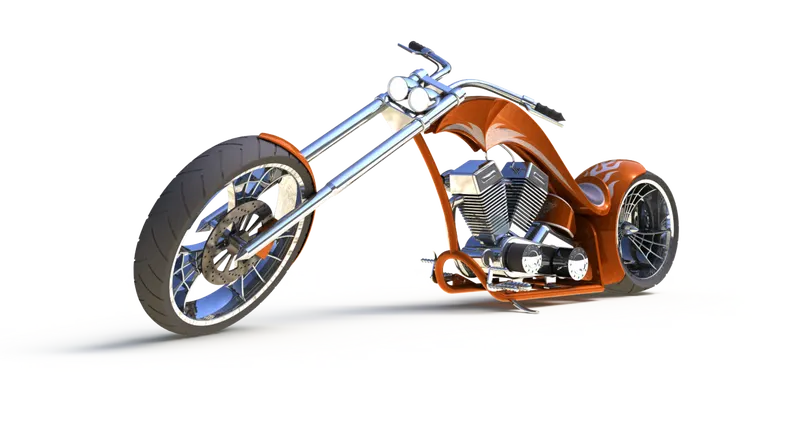
Rendering with Solidworks Visualize:
- Open solidworks visualise from start menu.
- Create the new project and import the model.
- Apply the appearnces,scenes and cameras.
- Preview and render it out.
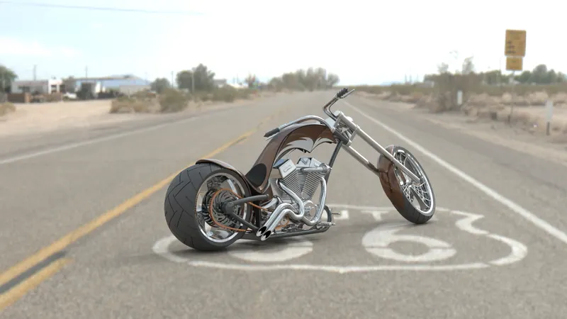
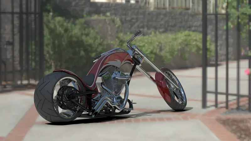
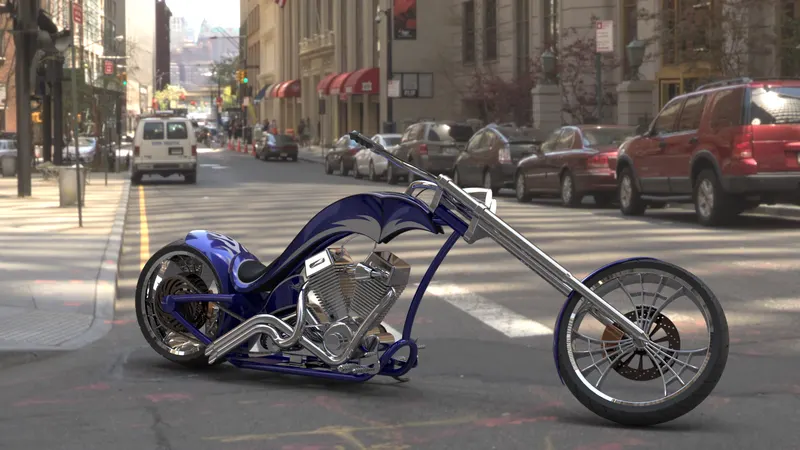
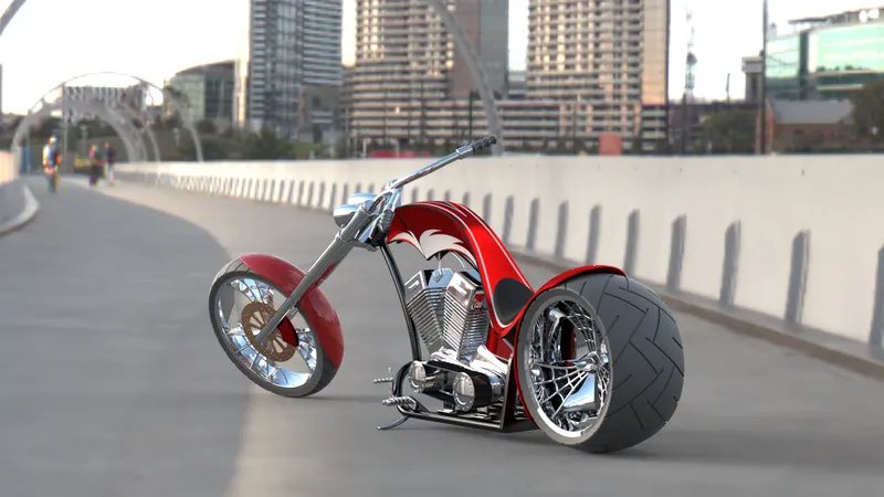
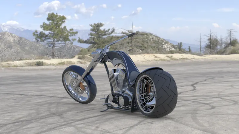
Rendering images of Solidworks Visualize:
Route 66:
Sunny Driveway:
Downtown:
Docklands Bridge:
Mountain Dot:
Conclusion:
- Sketching and modelling of individual parts by using with different features can be learnt and also gain a practical knowledge on how to design the different components by using solidworks.
- Got a detailed information on how to assemble different components into single assembly file by using the mate relations and finally made the chopper assembly.
- Gain a knowledge on how to apply decals,change scene composition,adding lights and cameras and how to generate the rendering by using photoview 360 and solidworks visualize.