Week 8 - Challenge 1 - Draft Analysis on a Fan Cover
DRAFT ANALYSIS ON A FAN COVER
Aim :
The main objective of this project is to perform the draft analysis on a fan cover using the proper tooling axis direction by bisecting method.
Introduction :
Draft and its importance -
A draft is a slant (Angles or tapers) which is applied to each side of most features of an injection molded part, that is positioned to run toward the direction of mold's pull and parting line which helps with easy releasing the part from the mold.
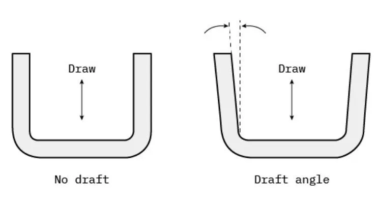
While designing or manufacturing the parts, draft is crucial in order to meet the quality standards.Without proper draft, major problems like friction and vaccums can arise in the injection molding process that increase the time and cost of production.These issues can damage both the part and mold that directly results in reduction of production efficiency.
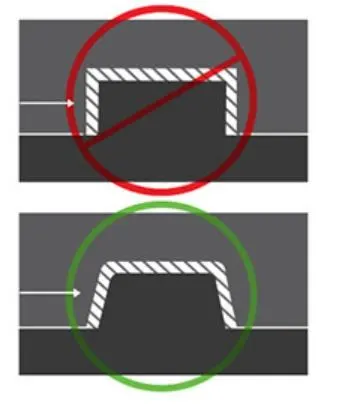
So by adding draft angles to the design,we can easily avoid these problems and lower the cost of production.Draft will allow parts to release from the mold with ease, which will result in better cosmetic finishes and fewer rejected parts.In addition, draft can also help us to avoid costly elaborate ejection setups.
Draft analysis -
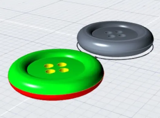
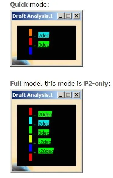
Draft analysis is a method of checking the draft angle on various faces of a part with respect to a particular tooling direction.This method is performed based on color ranges with various identifying zones on the analyzed element where the deviation from the drfat direction at any point, corresponds to specified values.This allows to verify whether the product will be easily remove from the mold, or if you will need to correct the draft to faciliate the mold release.
Tooling axis -
Tooling axis is the direction in which the tool operation can be performed.In injection molding, the direction in which the mold opens or closed is known as tooling direction.
Creating tooling axis(By bisecting method) for given fan cover model :
- The given input is a class A surface component.So initially, check for any surface discontinuities using boundary feature.
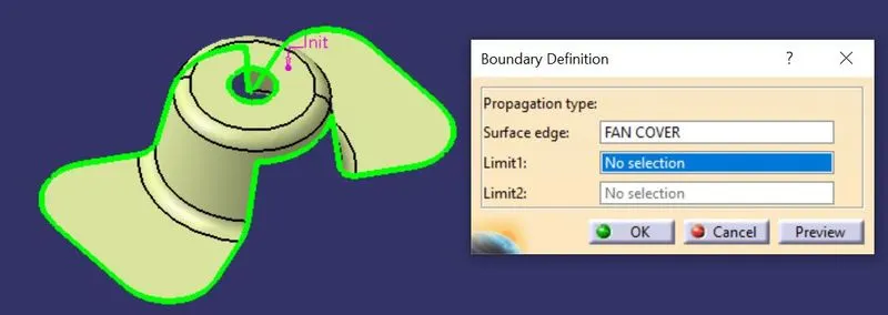
- After that, manually visualize the various directions of component and assume the dummy tooling axis direction that helps us of giving idea for creating main tooling axis.
- For that, create the axis system at the position as shown below :
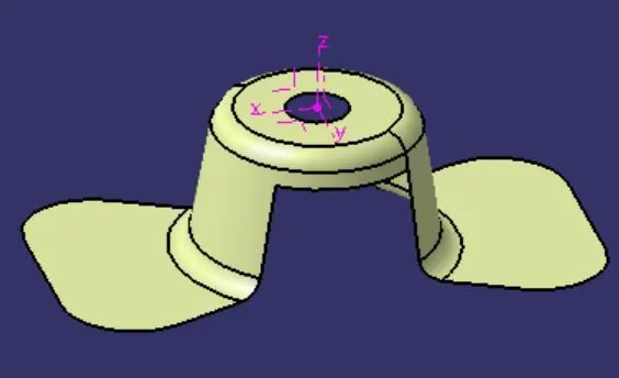
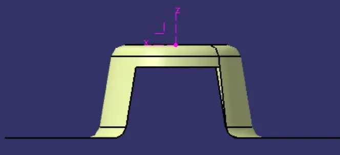
- Assume tooling axis in X direction, the hole operation cannot able to be performed.
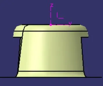
2.Assume tooling axis in Y direction, the hole and side walls cannot able to be performed.
3.Assume tooling axis in Z direction, all the features are able to perform well.
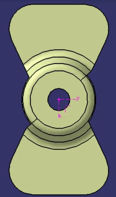
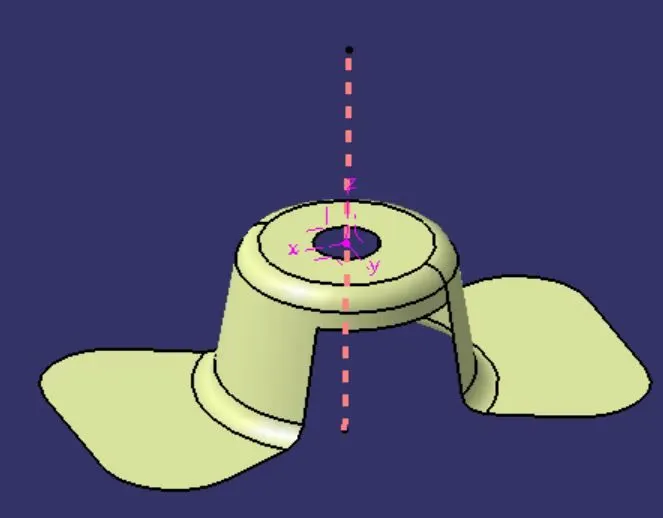
- So create dummy tooling axis in Z direction and it is used as reference for main tooling axis by bisecting method.
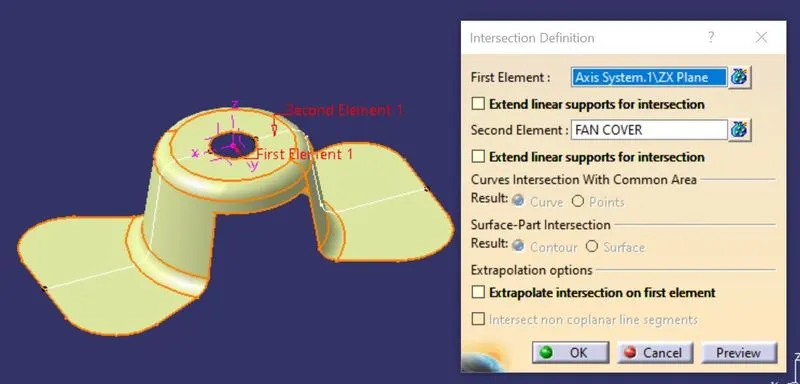
- Next develop the intersection curve along XZ plane using intersection curve feature.
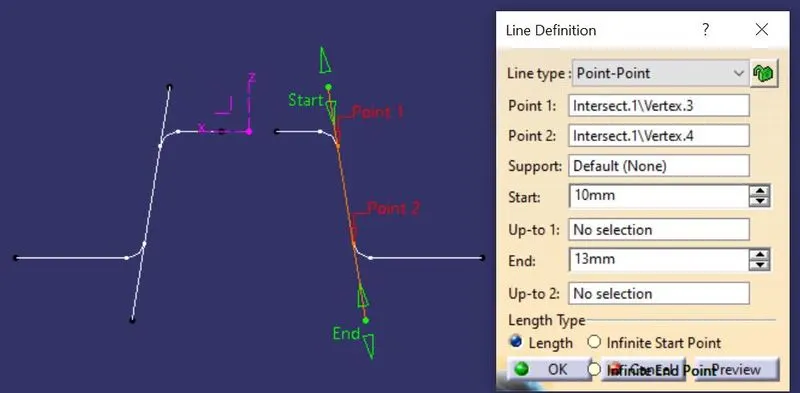
- Create two lines parallel to side walls and using that two lines create the bisecting line as shown below.
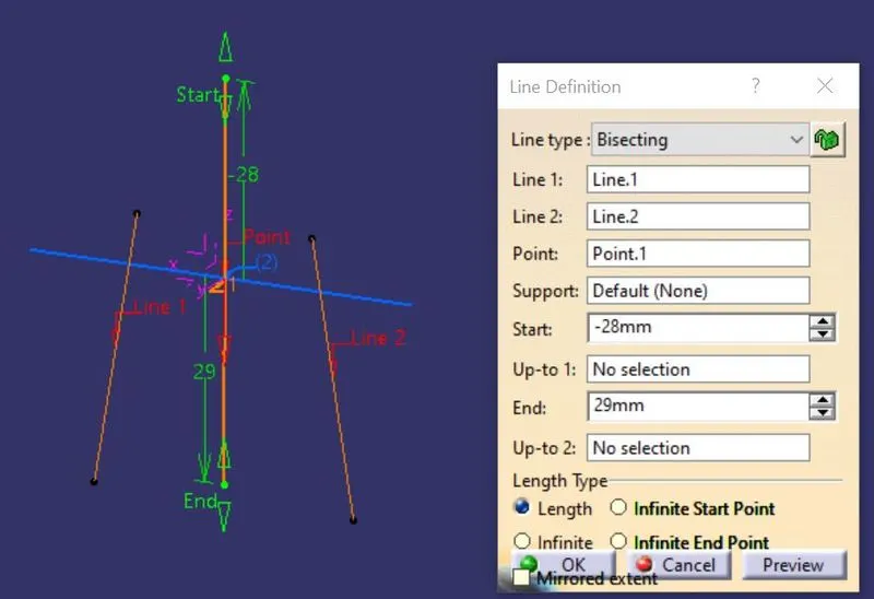
- Similarly develop the intersection curve along YZ plane using intersection curve feature.
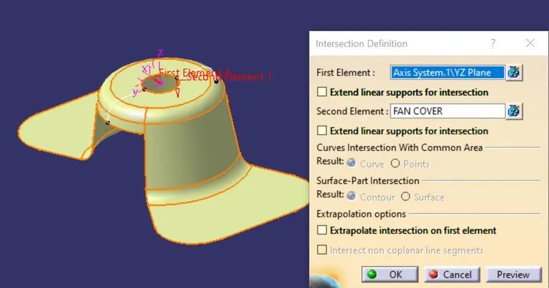
- Create two lines parallel to side walls and using that two lines create the bisecting line as shown below.
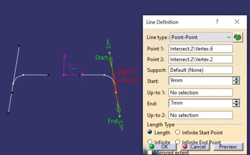
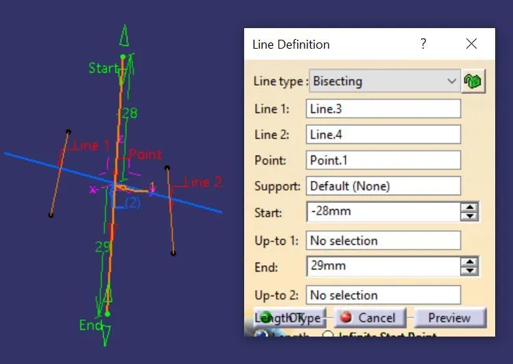
- Using that two bisecting lines, create the another bisecting line i.e,the main tooling axis indicate in orange colour as shown below.
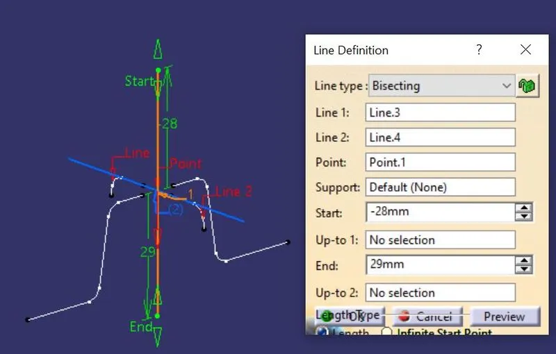
- So the main tooling axis direction can be properly defined using bisecting method.
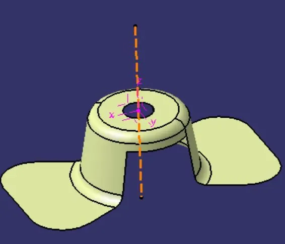
- Using the publication option, publish the component and tooling axis for easy recognisation irrespective of observing from any geometrical sets.
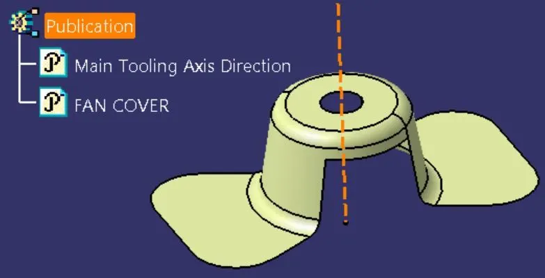
Draft analysis on fan cover using defined tooling axis direction :
- Mode of material plays a important role for performing draft analysis,because the tool defines the draft angles based on the material properties.If material mode is not proper it gives warning popup message.So keep it on proper material mode as shown below.
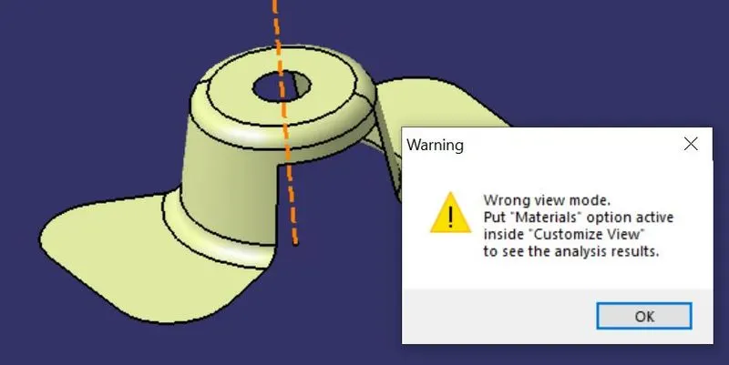
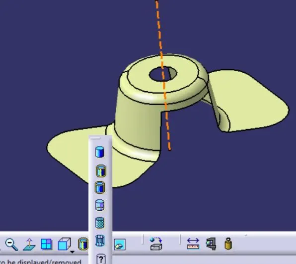
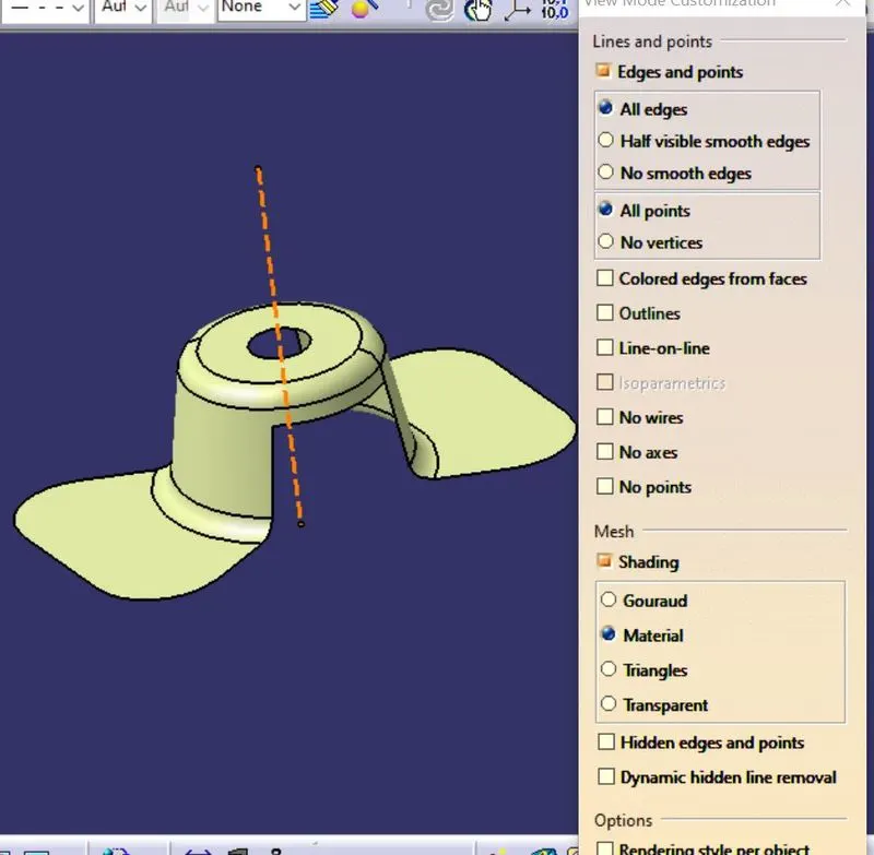
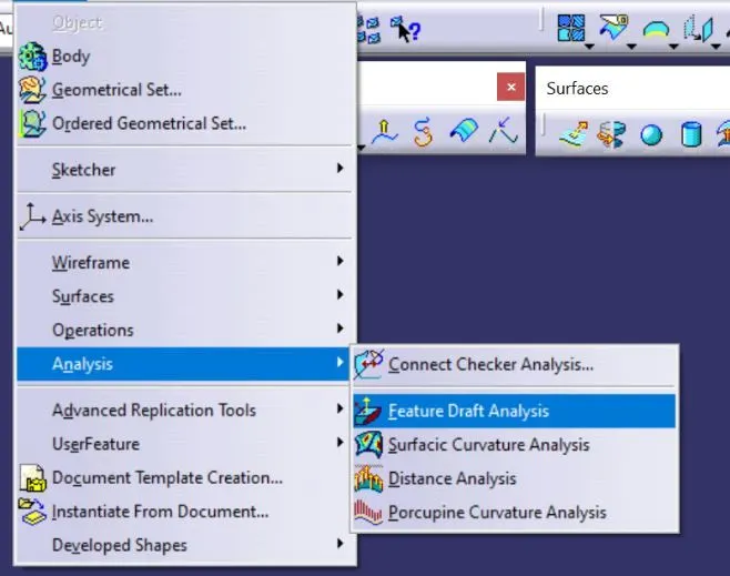
- After setting proper material mode, click on feature draft analysis from the insert-menu and dialogue box is opened as shown below.
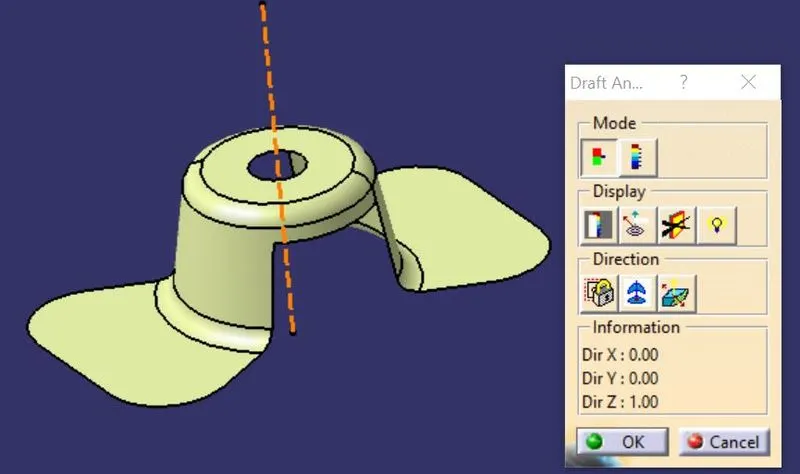
- Using compass option from box, align the current draft direction with the main tooling axis direction.
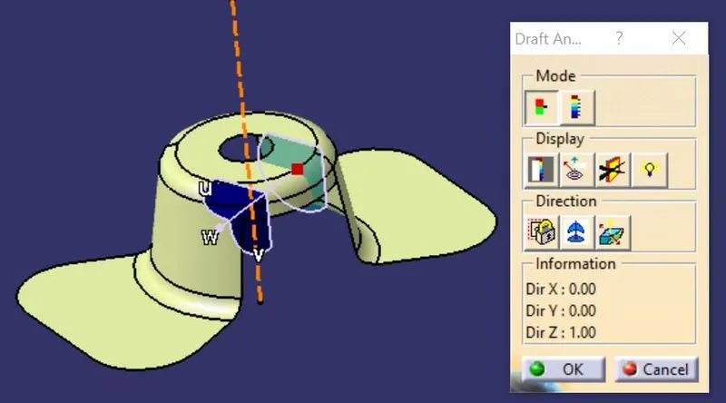
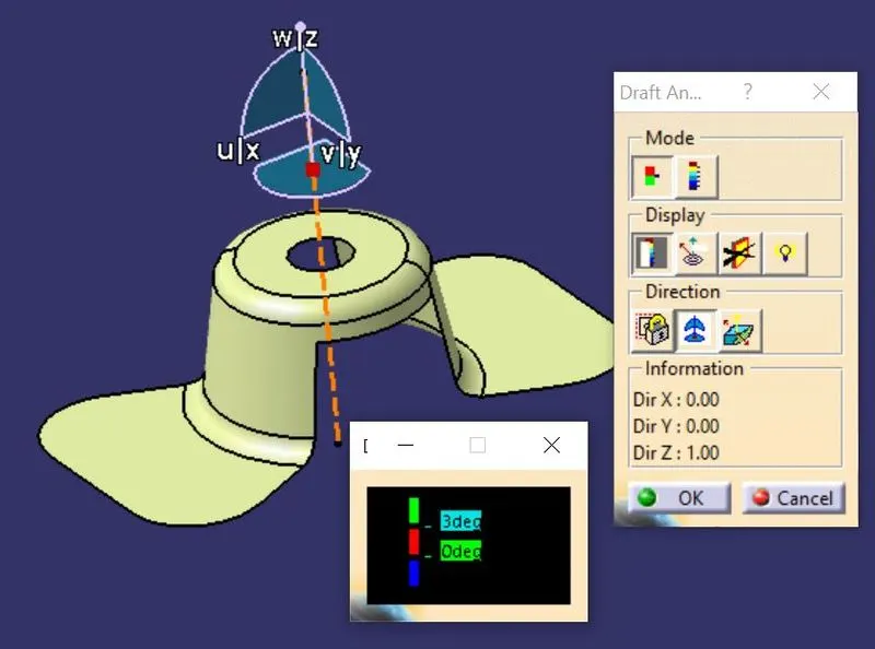
- Click on required draft face of the surface of component, so then the component faces undergoes with colour zones as shown in below figure.Here the method is performed by quick analysis mode.
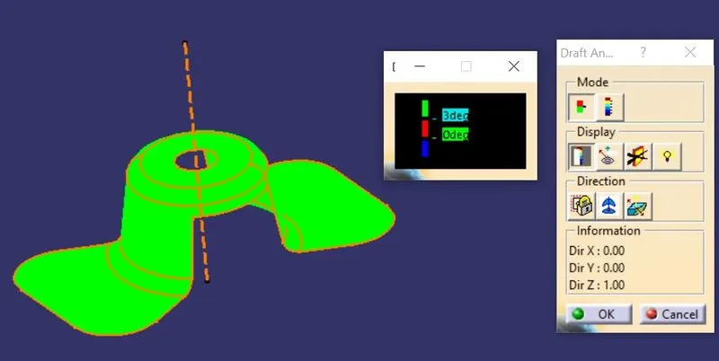
Green colour - Positive draft
Red colour - Below positive draft
Blue colour - Negative draft
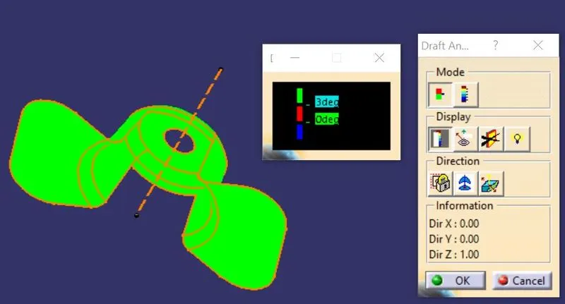
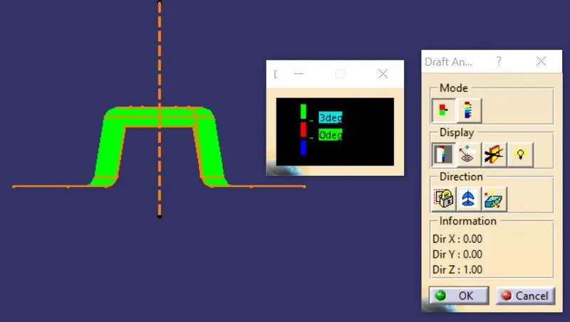
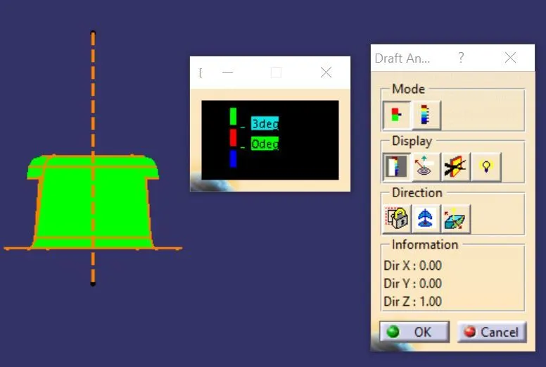
- As shown in above figures, the draft angle value will be given as 3 degree and it meets the analysis with that draft angle which represents postive draft as green colour.So the given fan cover component is able to manufacture in tooling direction direction along Z axis with 3 degree.
Conclusion :
Hence, successfully performed the draft analysis on fan cover with defined tooling axis direction using bisecting method of satisfying the requirements and also learnt the importance of draft analysis for the manufacturability.
THANK YOU