Roof challenge
DESIGN AND ANALYSIS OF CAR ROOF(BIW)
Objective:
The main theme of this project is-
- To design the car roof with ditch area and its respective reinforcements of front roof rail, Rear roof rail, Reinforcement roof centre and Bow-roofs from the given roof styling body and master sections from styling department.
- To study the roof curvature and to perform the calculations for heat distortion and snow load criteria to determine whether the roof can withstand from extreme heat and snow conditions as per the alloted position of Bow roofs.
- Perform the section inertia analysis for knowing its bending strength.
- Perform the drafting analysis, as to prove the designed parts have no negative drafts with respect to the tooling direction.
Introduction:
Roof is the major structure of an automobile BIW commodity which sits above the passenger compartment and houses the vehicle as shielded part which safeguard the occupants or passengers from sunlight, rain, snow, wind and dust etc.
In the past, roof was introduced as cover for passenger compartment but later on, it also used as a luggage carrier, sunroof and in recent past years with the introduction of the solar panelled electric vehicle got a major boost in the automobile industry.
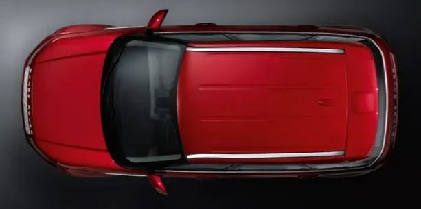
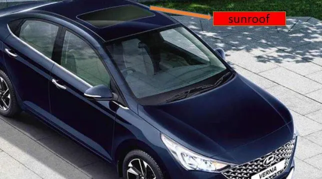
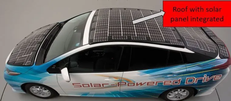
Roof has the following functions
- Protects from external damage
- Protects the passengers and vehicle from accidents
- Protects the passengers or occupants from heat,rain and snow etc
- Gives a aesthetic aerodynamic shape to the vehicle
- Acts as sonal panelled roof in electric vehicles
Since the roof has numerous functions, it has to be stronger enough to withstand the damage experienced by it.To have a good strength and stiffness, the roof is made with different components such as Front,Centre and rear roof rails, Bow roof rails.
Considerations to be taken while designing roof-
- Visibility criteria
- Head room clearance
- Material thickness
- Mastic data
- Heat distortion and snow load criteria
- Draft analysis
- Safety parameters
Roof crush analysis of passenger car:
Today roll over crashes or rollover accidents of the car are increasing day by day in the country which results in vehicle damage such as deformation of roof and its supporting structures.This roll over accidents not only effect the vehicle damage but also effects the passengers or occupants inside the car are experience major injuries like neck, head and spine injuries.So as to reduce the injuries of a passenger from major fatalities it is very important to provide safety for car.Though the safety is provided by seat belts and airbags during accidents, the passenger must have sufficient space for survival in the car during accidents. The roof of the car must have high strength to resist the crush force to avail the passenger some space for survival.
So the strengthening of roof is suggested as an best countermeasure for such injuries and for that the roof crush test is to be carried out.The roof crush test is regulated by the American standard FMVSS-216 which establishes a strength requirements for the passenger compartment in order to reduce deaths and injuries due to crushing of the roof into occupant compartment in rollover crashes.In practice this standard establish a quasi-static test although it simulates experimentally rollover accident.This standard applies to passenger cars, trucks and buses with a gross vehicle weight rating(GVWR) of 2,722 kilograms or less.
For this test, firstly the passenger car is rigidly positioned or placed on the surface by closing all the doors and windows.After that for impacting the load on the roof, a staic load is applied and for testing, device is used.The test device is a rigid unyielding block whose lower surface is a flat rectangle measuring 762 millimeters by 1829 millimeters to achieve the specified resistive load when applied to the forward edge of a vehicle roof.The resistive load to be achieved is equal to 1.5 times the unloaded vehicle weight of the test vehicle or 22,240 Newtons whichever is less.
This force shall be applied in a downward direction perpendicular to the lower surface of the static loading device at a rate of not more than 13 millimeters per second until reaching the compliant resistive load.The test shall be completed within 120 seconds.The staic loading device shall be guided throughout the test so that it moves, without rotation in a straight line with its lower surface oriented as shown below figures.
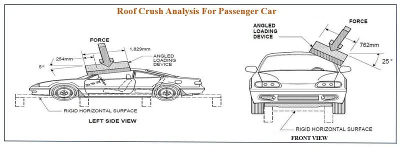
After the test is completed, analyze the roof parameters on which positions the roof can be deformed more with repect to the standards.So that we have to rectify and improve the roof strength where the deformation will be more by changing its design considerations, roof curvature or material standards etc; which helps of increasing vehicle safety as well as passengers or occupants safety.
Design Methodlogy:
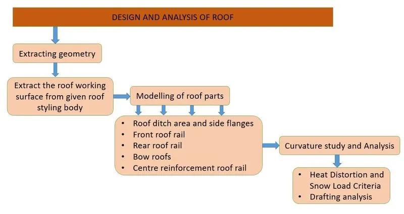
Design Procedure:
- First load the given roof styling body to the NX interface.
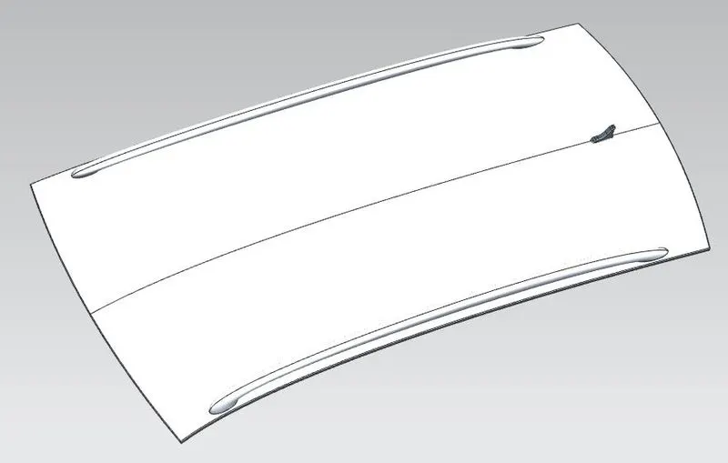
- Using extract geometry feature,extract the working surface of roof.
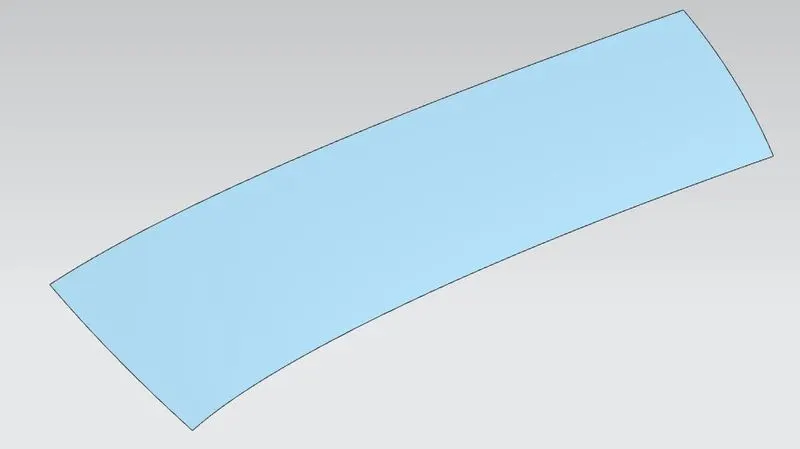
So using this working surface, create all the components of roof as follows:
1.Roof Ditch area and side flanges
While designing the roof ditch area, particularly at the front ditch area visibility criteria is the important parameter to be taken.
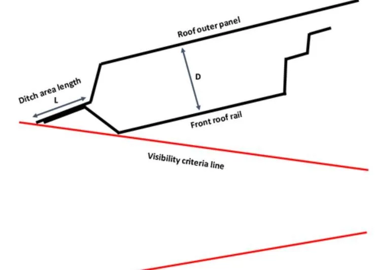
As shown in figure, L is the length of front ditch area.As 'L' vlaue increases, the visibilty to the driver will be reduces.So while designing front ditch area we have to follow the appropriate length.Here the reference for generating front ditch area can be taken from the given front roof rail master section.
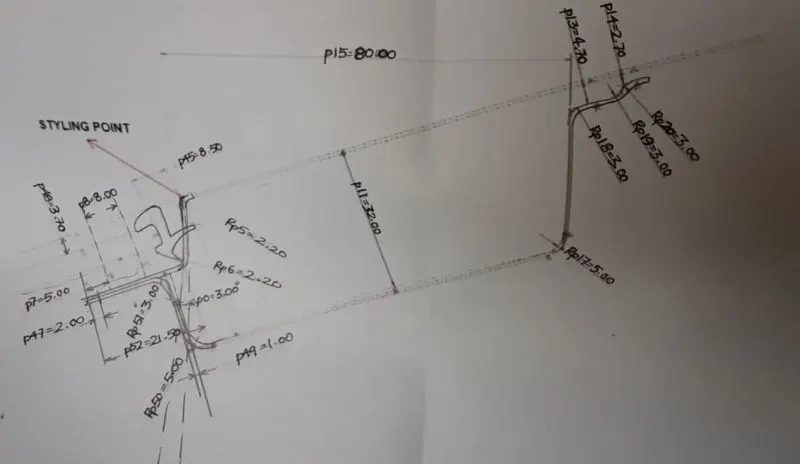
From the above master section, I have observed that-
Minimum tool opening angle-3 degrees
Ditch area length(L) will be-21.5mm
Coming to designing
- First the side flange can be created with 15mm length of opening angle 3 degrees
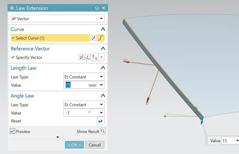
- Similarly create the another flange with length 21.5 mm which is ditch area length.
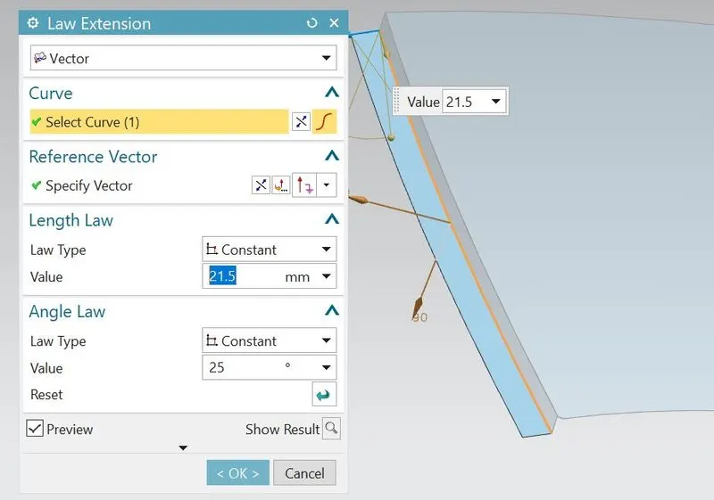
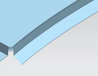
- So the front ditch area flanges will be completed and then after create the roof side flanges as well.
- Coming to rear ditch area creation, we have to observe the rear roof rail master section.
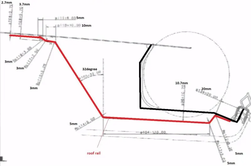
Actually the rear roof ditch area will be connected with back door.So for proper opening of back door,the rear ditch area will be properly designed with respect to the back door opening angle.As shown in figure, there is circle reference indicates opening position of back door with respect to the rear ditch area.
- So as following the above considerations from master section, create the rear roof ditch area with essential flanges.
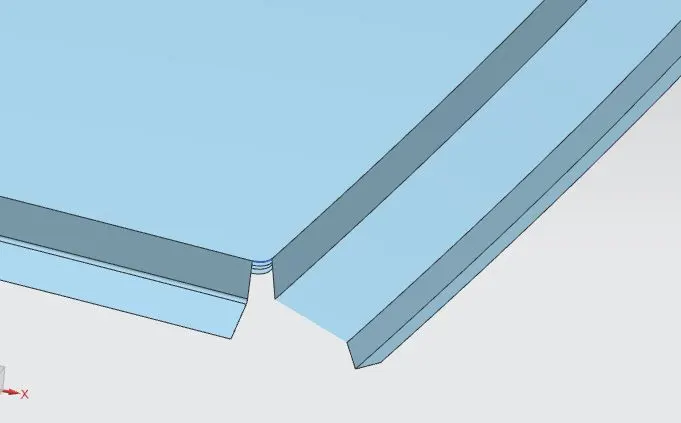
- Then after bridge the gap between front ditch area to Side flanges and rear ditch area to side flanges and then apply the required face blends or edge blends at front and rear ditch areas following the radius provided in the master sections.
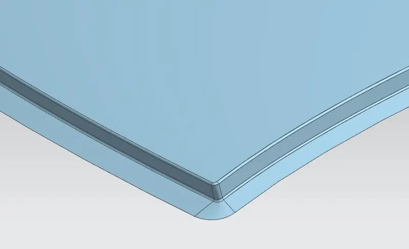
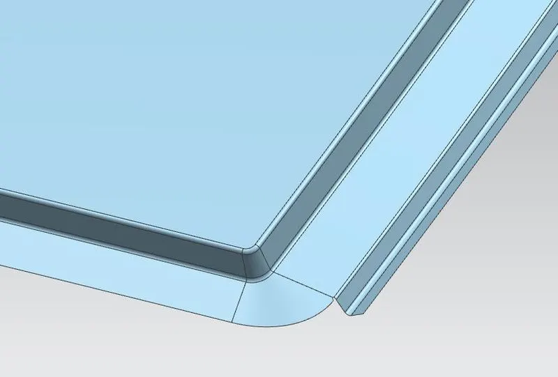
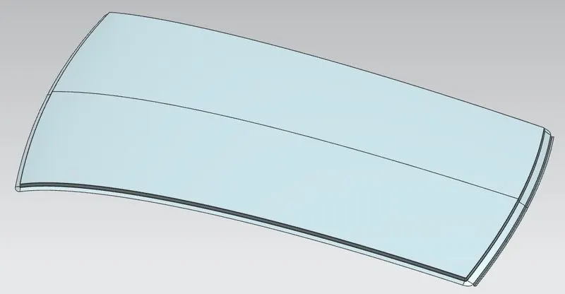
- Mirror the roof with respect to XY plane to get complete roof outer panel and sew it together.
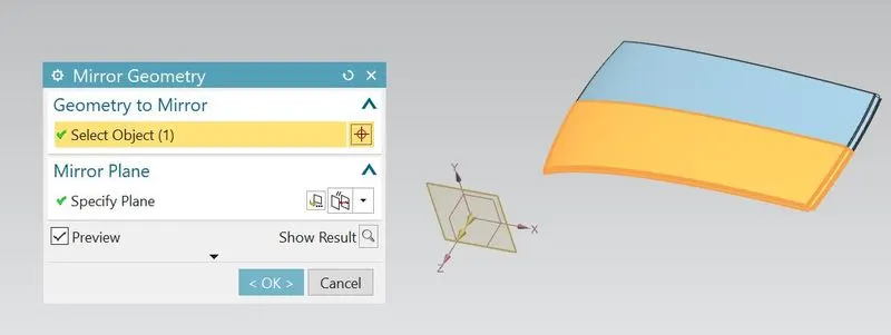
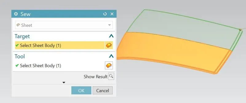
- Thcken the roof panel to 0.75mm
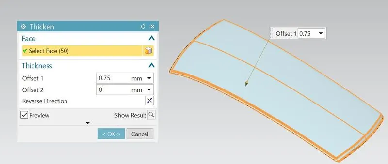
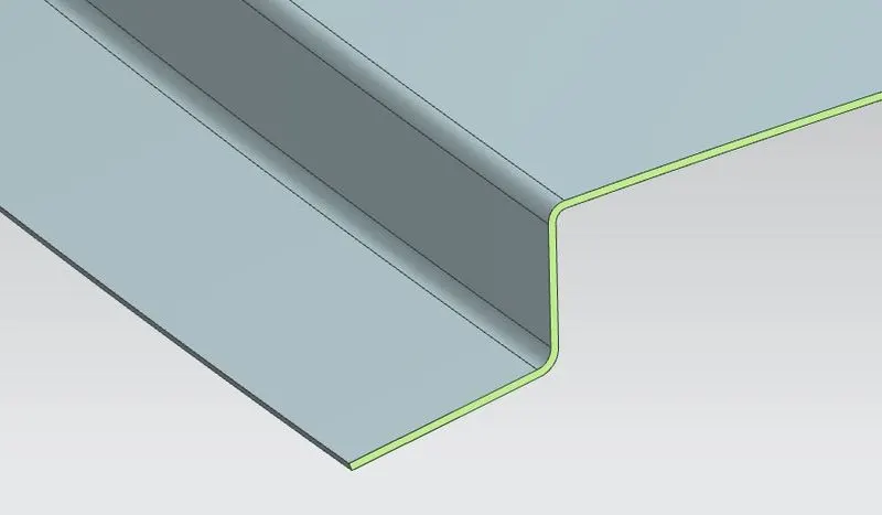
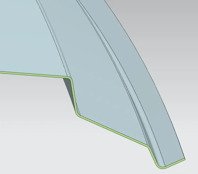
- So the roof outer panel(with ditch areas and side flanges) will be completed.
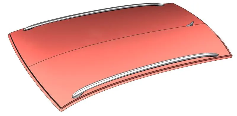
2.Front Roof Rail
Front roof rail is the strengthening component which provides the strength to roof at front side and acts as intermediate component in between front roof and the windsheild glass.
So for designing the front roof rail, I have taking reference of given front roof rail master section.
After the observation of master section-
For visibility criteria-Front flange length is 21.5 mm
For Headroom clearance-Depth will be 80mm(As the headroom clearance increases which decreases the inner compartment.So maintain 80mm clearance as per master section)
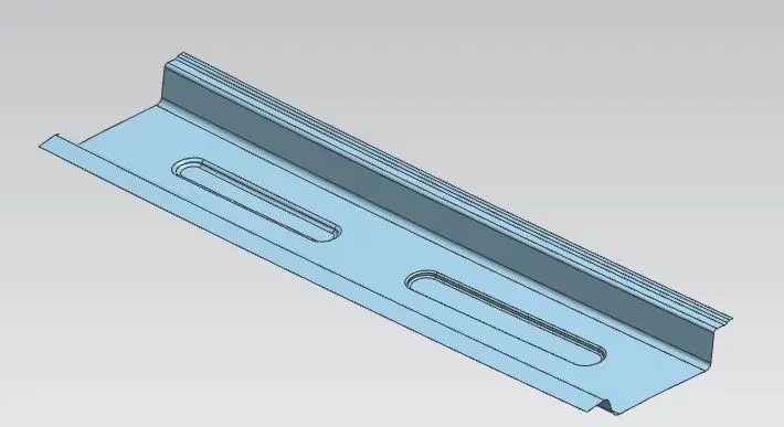
- Using the offset feature, offset the roof surface to required depths and then create the respective flanges as following the master section and then apply face blends.
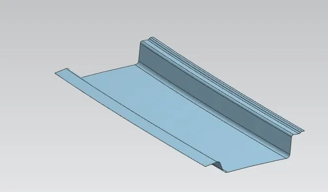
- For reducing roof weight and to increase the strength, I have create the embosses as shown.
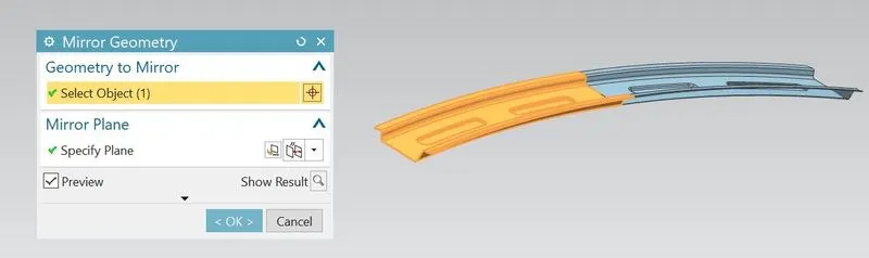
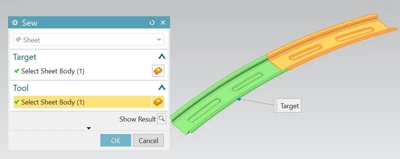
- Mirror the roof rail with respect to XY plane to get complete front roof rail and sew it together.
- Apply the thicken with depth 0.75mm
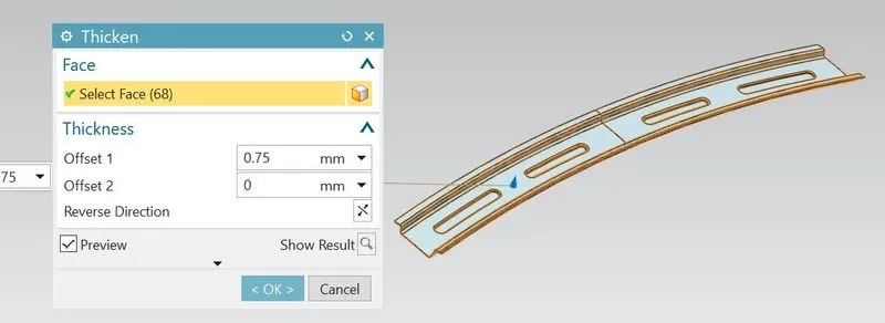
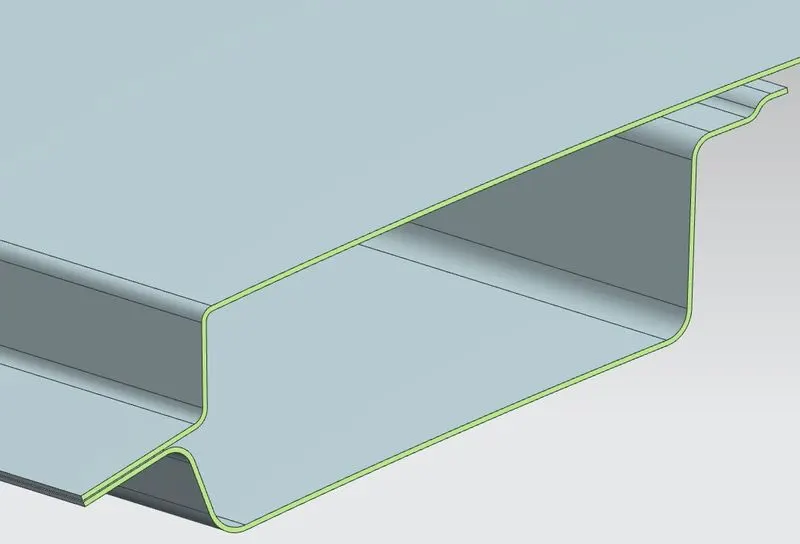
- So the front roof rail can be completed.
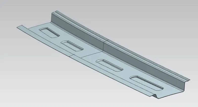
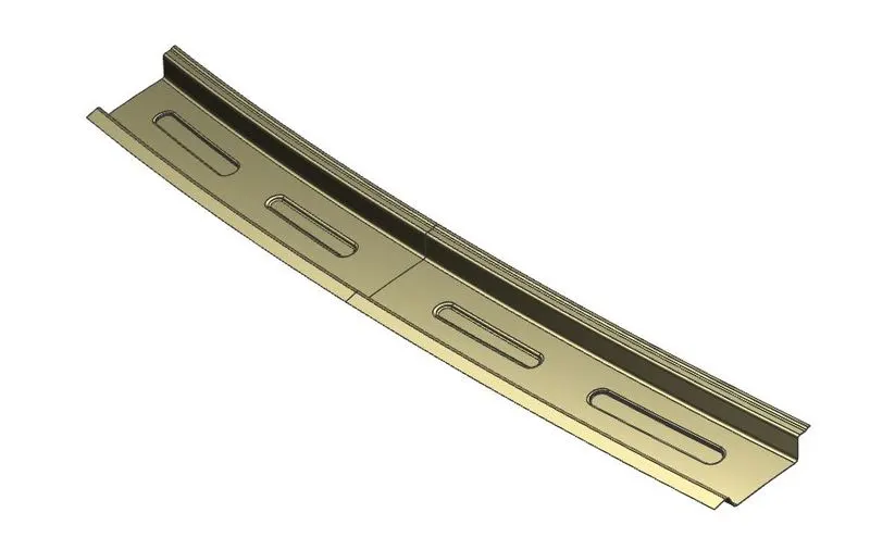
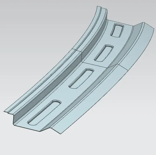
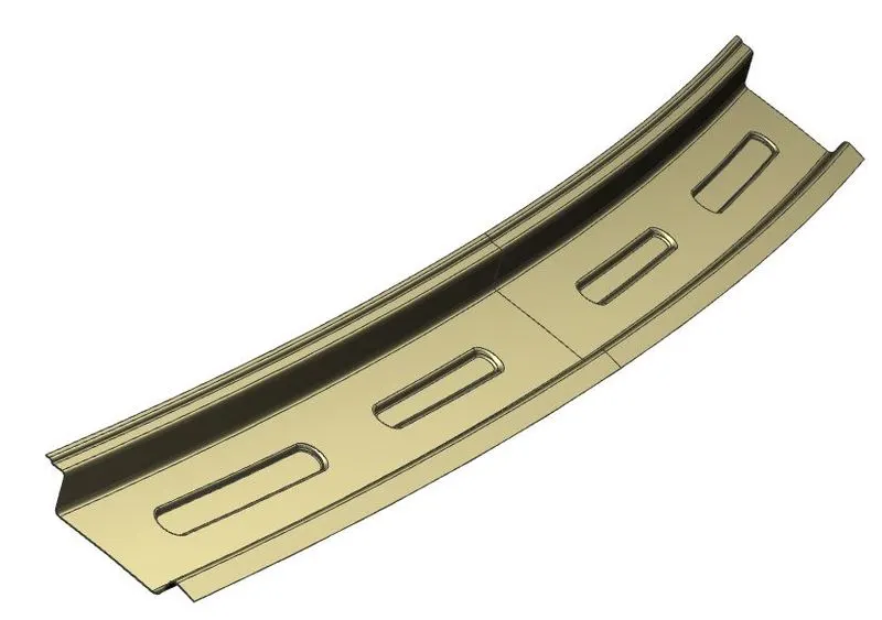
3.Rear roof Rail
Rear roof rail is the strengthening component which provides the strength to roof back side and acts as intermediate component in between back of the roof and the back door.
So for designing the front roof rail, I have taking reference of given rear roof rail master section.
- Similarly as front roof rail of using the offset feature, offset the roof surface to required depths and then create the respective flanges as following the master section and then apply face blends.
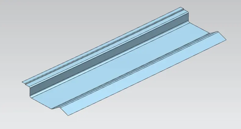
- For increasing strength to component, I have created the embosses as shown.
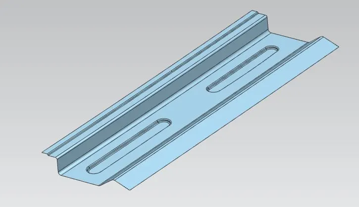
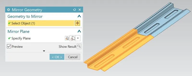
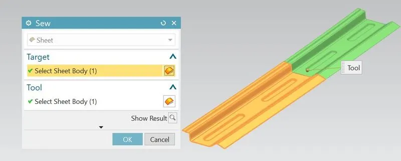
- Mirror the roof rail with respect to XY plane to get complete rear roof rail and sew it together.
- Apply the thicken with depth 0.75mm
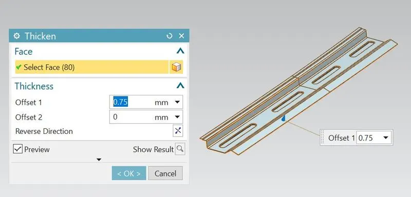
- So the rear roof rail can be completed.
4.Centre Reinforcement roof rail
Centre roof rail is the strengthening component provides the strength effectively at flat areas and it acts as a intermediate component between the roof centre and B-Pillar support.
Here I have considered
Roof length-80mm
Roof depth-10mm
- For creating this roof rail at the centre of roof,I have created the datum plane at centre and generate the mid intersection curve using that datum plane.
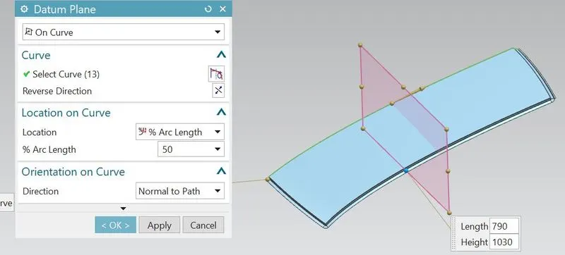
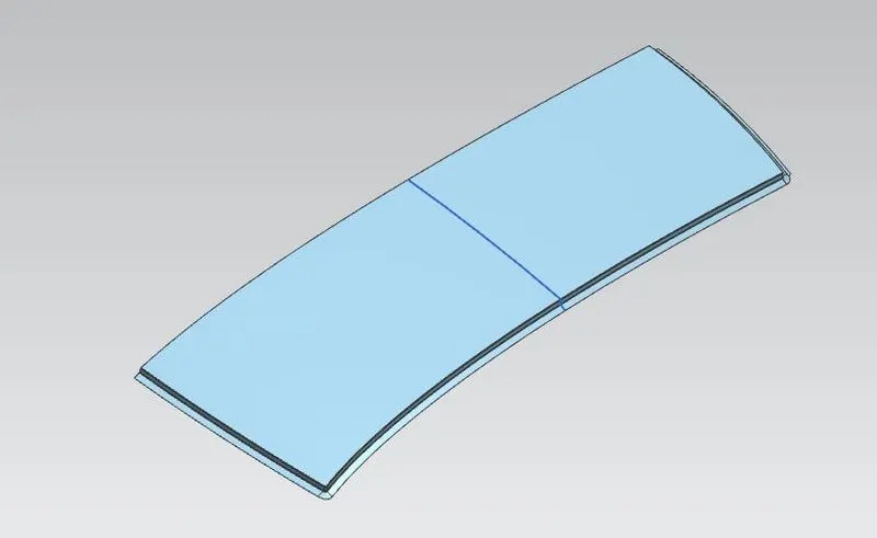
- Using that intersection curve, generate offset curves on face for defining respective flange distances.
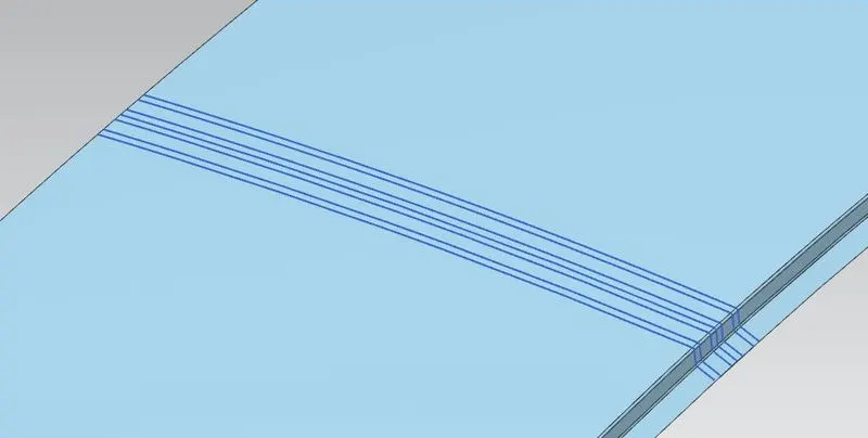
- Using the offset surface feature, offset the roof surface to required depths and then trim that sheets to required portion using previous created offset curves as boundary curves.
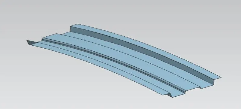
- Apply the face blends or edge blends.
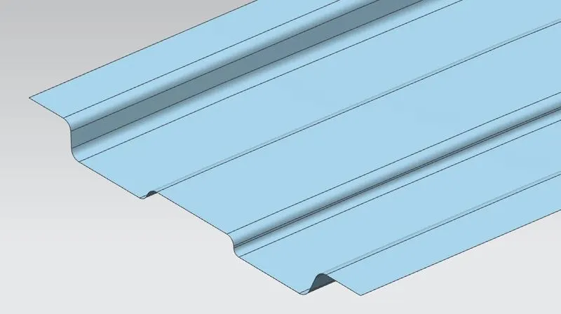
- As per design considerations,the end of roof outer panel and centre roof rail is joined with spot welds.For that I have offset the extreme end flange surface of roof to 1.5mm and trim to required portion in order to connect the centre roof rail end with roof outer panel.
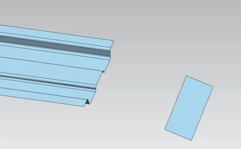
- Bridge the curves in between two sheet surfaces and using that curves fill the tangant surface in between them.
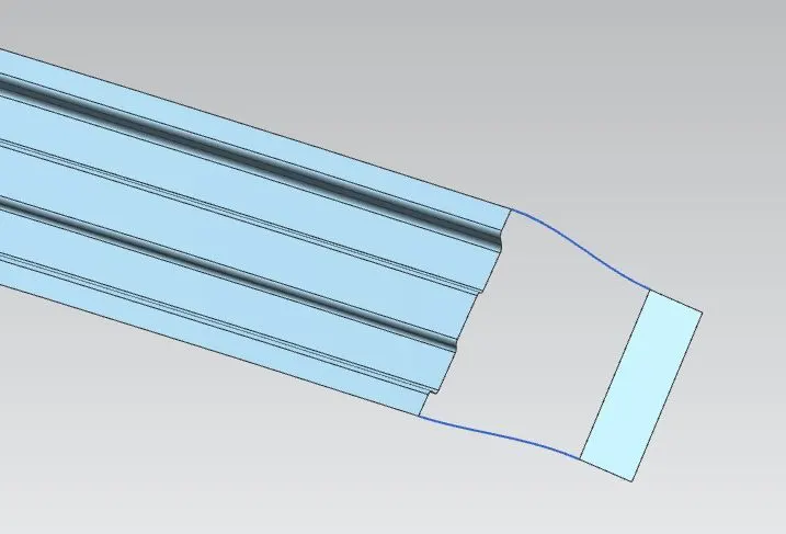
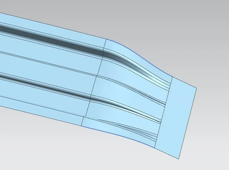
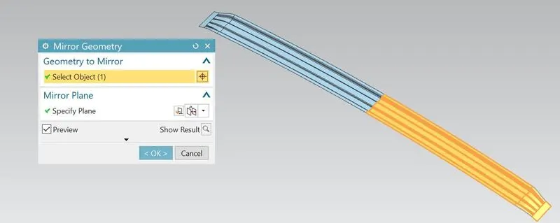
- After that mirror the roof rail with respect to XY plane to get complete roof rail and sew it together.
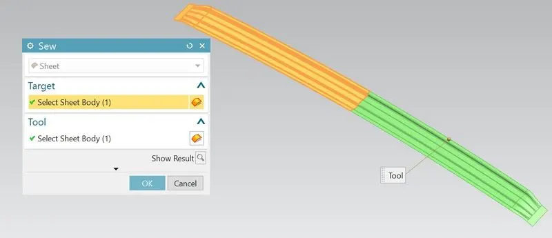
- Thicken the roof by using thicken feature.
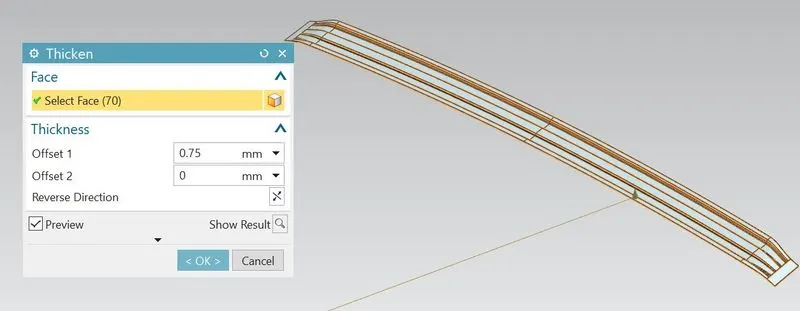
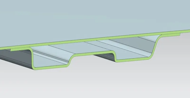
- So the centre reinforcement roof rail can be completed.
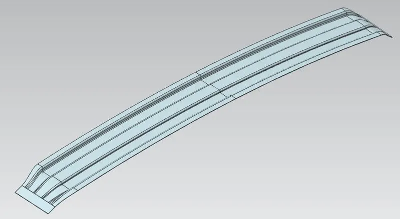
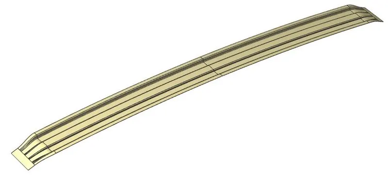
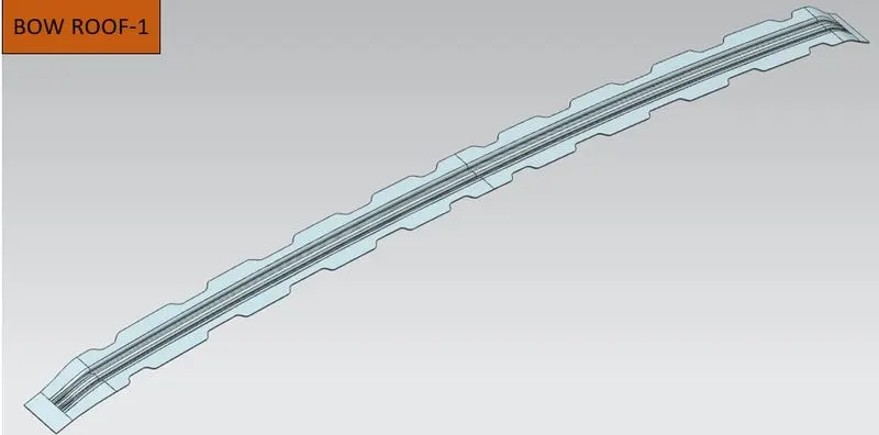
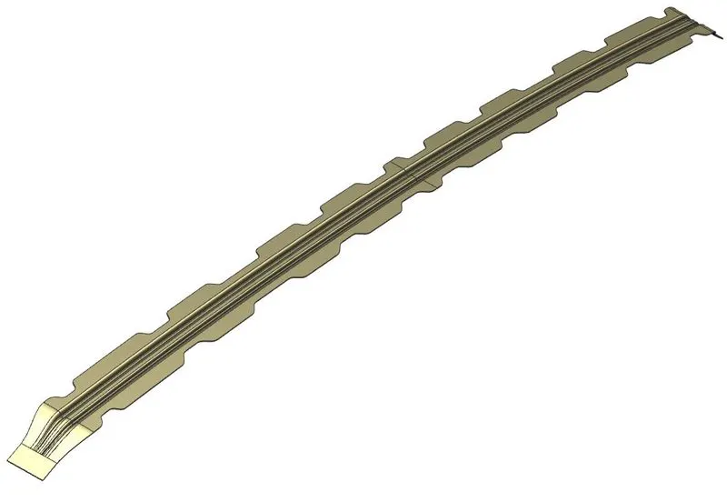
5.Bow Roofs(1 &2)
Bow roofs are the sheet metal strengthening components, usually spot welded to the BIW inner frame, forming the inner structure of the vehicle body.Its primary function is to supporting the roof panel loads and improve the torsional stiffness and load bearing capacity of the roof.The number of bows provided on the roof is mainly depends upon the roof curvature and its overall dimension.Usually bow roofs are integrated on roofs at flat areas.More in the curvature of roof and less flat area will drastically reduces number of bows.These bows can be positioned in many ways-
- Apart from centre roof rail with symetrical distance on both sides
- Only before or after the centre roof rail position
- In some cases, bows are integrated on the centre roof rail.
So the exact position of bows roofs will be justify by the curvature study.Here I have created only the two bows-Bow roof1 in between front roof rail and centre roof rail, Bow roof2 in between rear roof rail and centre roof rail.Both bows are in symetrical distance from the centre roof rail and all the design considerations or shape or dimensions are taken similarly.
The method of designing the bow roofs is same as centre reinforcement design except the dimensions and roof curvature will be different at their respective roof positions.
Bow Roof 1:
Bow Roof 2:
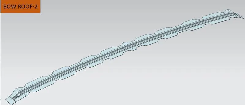
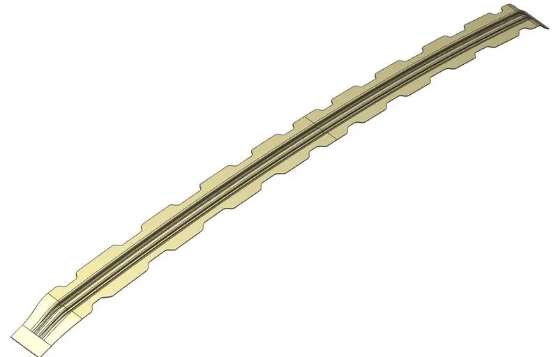
Curvature study:
After the designing of all components, we have to perform curvature study on the roof.This curvature study examines the positions of reinforcements to check whether the roof having enough strength as per the positions of reinforcements and can withstand from deformation at different conditions.Here the curvature of roof can be examined based on two conditions:
1.Heat Distortion Criteria and its Calculations
During in summer days or in some high temperature regions or countries, the roof of the car is exposed to the more heat.At that time,the roof can be capable of withstand from the deformation.So for that while designing the roof, heat distortion study is the important parameter to be considered.This study helps us to check the roof can withstand from deformation or not as per the postion of bow roofs.
For that,we have the prediction formula;
Heat Distortion(W)=1.73x10^(-3)xL+1.85X10^(-8)x(R²/t)+1.10x10^(-3)xl-2.68
Where,
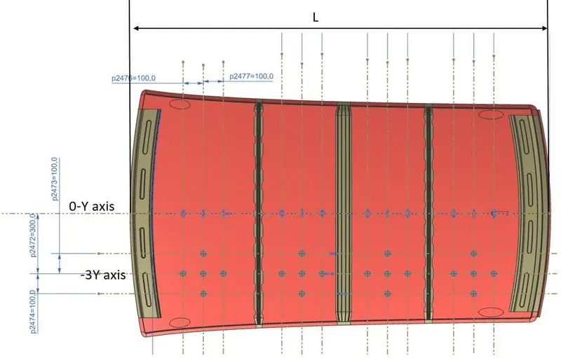
L : Roof length in X-direction(mm) [Roof dimension with 0Y
R : Roof curvature
R= 2(Rx*Ry)/(Rx*Ry)
Rx : X curvature
Ry : Y curvature
t : Roof plate thickness(mm)
l : Bow Roof Span(mm)
Judgement condition : OK<2.7mm< NG
Here,the calculations are taken in the following cases:
1.Front roof rail(FR)-Bow roof rail1(Bow1)
2.Bow roof rail(Bow1)-Centre roof rail(CR)
3.Centre roof rail(CR)-Bow roof rail2(Bow2)
4.Bow roof rail(Bow2)-Rear roof rail(RR)
Steps followed:
- Draw the 0-Y axis line for indicating exact centre intersection of the roof
- Draw the line in downwards at a distance of 300mm apart from 0-Y axis line(-3Y)
- Offset the -3Y line at a distance of 100mm on both sides
- Now the vertical centre lines are drawn between each adjacent roof rail rail edges and from that centre lines,offset the lines to distance 100mm on both sides.
- Generate the intersection points where the vertical lines and horizontal lines are intersected.
- Make all the sketch geometry into construction geometry except the intersection points and exit from sketch.
- Project the intersection points onto the surface of roof using 3D project curve feature.
- Using three point arc,join the intersection points and measure the minimum radius(Ry& Rx values)
- Measure the overall length of the roof(L) except ditch area and measure Bow roofs span(l).
- Once all the values will obtained, calulate the 'W' value using prediction formula.
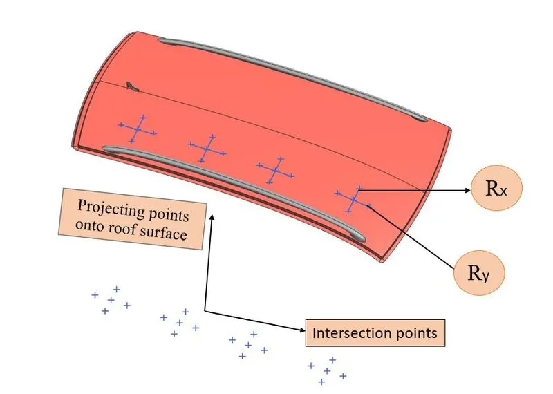
The measured values and the final result can be represented in the folowing table:

From the above table, I have concluded that the value 'W' satisfying all cases i.e;less than 2.7mm[All cases(w<2.7mm)].So the roof can withstand from deformation as per the given respective position of bow roofs.
2.Snow Load Criteria and its Calculations
In some snow heavily regions or Snow covered countries, the snowfall will be more.At that situations, the roof of the car can be capable of withstand from that load when impacted.So while designing the roof of considering the snow parameters, snow load criteria study helps us of determining the strength of roof as per the position of bow roofs.
For that,we have the prediction formula;
Qr = [ly x t²]/[∝ x s x[(Rx+Ry)/2]²x10^(-8)]
Where,
∝ = My x Lx² x 10^(-12)
Where,
My = Y(Ly-Y)
Judgement condition : Qr> 3.1
t : Roof plate thickness(mm)
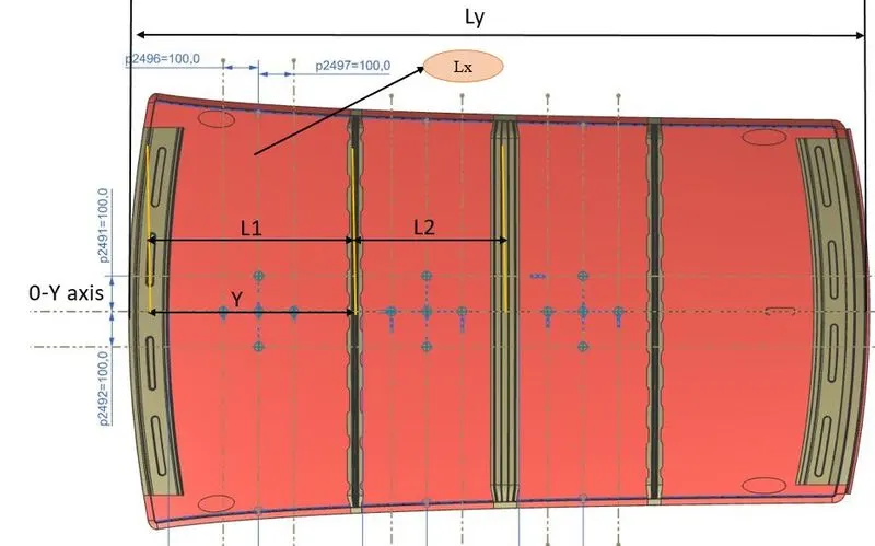
Ly : Distance between the front and rear roof rails on vehicle 0Y(mm)
Length of roof panel with the centre point between ROOF RAIL FR/RR as the reference point of the front/rear.
Lx : Distance between the left and right end of the roof on roof bow(mm).
Width of roof panel exposed on the surface
Y : Distance from FR roof rail centre to roof bow(mm).
S : Distance for which roof bow bears divoded load(mm)
where,
S = (L1/L2)+(L2/2)
ly : Geometrical moment of inertia of roof bow(Y cross section-mm⁴)
Rx : Lateral direction curvature radius of roof panel Y cross section on roof bow(mm)
Roof panel curvature radius of the length Lx in FR/View
Ry : Longitudinal direction curvature radius of roof panel X cross section on roof bow(mm)
Roof panel curvature radius of the length S in Side/View
Here,the calculations are taken in the following cases:
1.Front roof rail(FR)-Bow roof rail1(Bow1)
2.Bow roof rail(Bow1)-Centre roof rail(CR)
3.Centre roof rail(CR)-Bow roof rail2(Bow2)
Steps followed:
- Draw the 0-Y axis line for indicating exact centre intersection of the roof.
- Offset the 0-Y line at a distance of 100mm on both sides.
- Now the vertical centre lines are drawn between each adjacent roof rail rail edges and from that centre lines,offset the lines to distance 100mm on both sides.
- Generate the intersection points where the vertical lines and horizontal lines are intersected.
- Measure the Lx and Ly values as shown in the below diagram.
- Measure the Y, L1 and L2 values as shown in the below diagram
- Make all the sketch geometry into construction geometry except the intersection points and exit from sketch.
- Project the intersection points onto the surface of roof using 3D project curve feature.
- Using three point arc,join the intersection points and measure the minimum radius(Ry& Rx values)
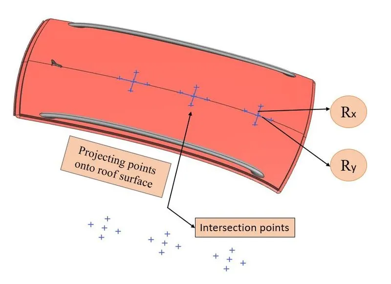
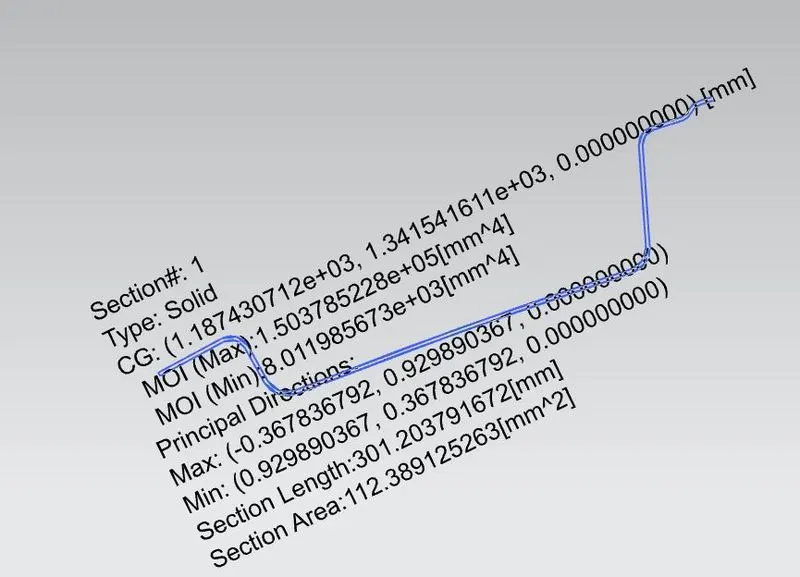
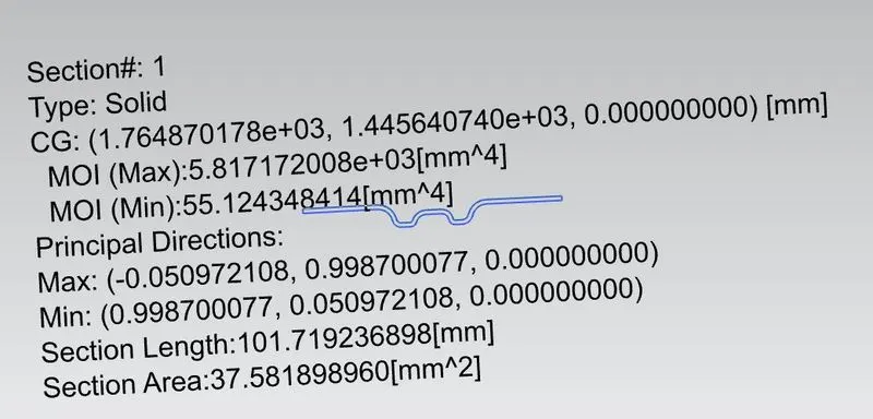
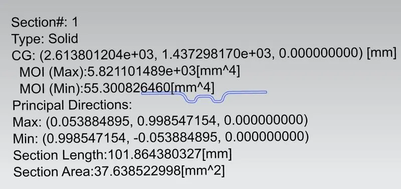
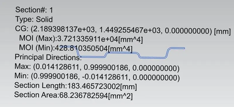
- For knowing moment of inertia(ly) values, make the section inertia analysis of the reinforcements at the 0-Y section.
Section inertia of Front roof rail
Section inertia of Bow roof-1
Section inertia of Bow roof-2
Section inertia of centre reinforcement
Section inertia of Rear roof rail
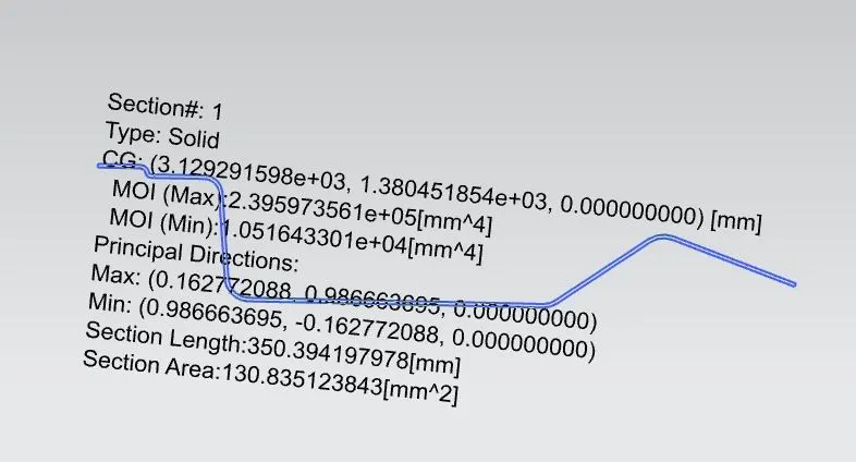
Among all the section inertia, we have to require only the three reinforcement section inertia because we have only the three cases.
For,
Case 1(FR-Bow1) : Iy value from Bow roof rail 1 section inertia
Case 2(Bow1-CR) : Iy value from centre reinforcement section inertia
Case 3(CR-Bow2) : Iy value from Bow roof rail2 section inertia
- So all the required values can obtained and then calculate 'Qr' value for each case.
The measured values and the final result can be represented in the folowing table:
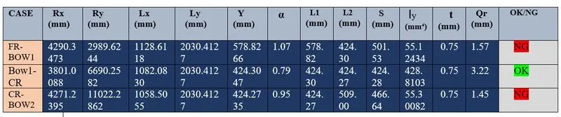
As seen in the above table , case1 and case2 does not satisfy the snow load criteria.So the roof cannot withstand from snow load.So in order to rectify that issue and to increase strength, we have three possibilities;
- Rechange the position of bows and its dimensions
- Changing the curvature of the roof
- Create the embosses on the roof surface
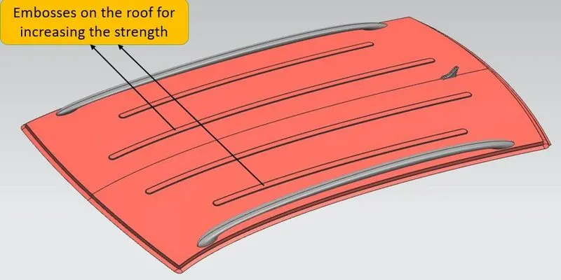
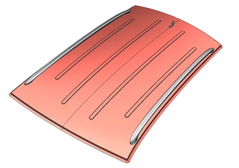
Among from that possibilities, I have creating the local embosses on the surface of roof which increases its strength.Rechanging the position of bow roof rails will take some time now and to request the styling team to change curvature, but in some cases they wont be accepted because it results of changing vehicle looks.so for that I have developed the aesthetic embosses on the roof surface as shown below:
Draft Analysis:
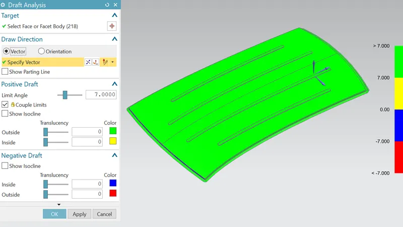
Draft analysis is a tool to check the correct application of draft to the faces of their part and verifies the draft angles or examine angle changes within a face.It commonly detect whether the designed component within the positive draft or negative draft.Positive draft means the angle of face with respect to the direction of pull is more than reference angle.Negative draft means the angle of face with respect to the direction of pull is less than the reference angle.
In the NX software, the draft analysis tool represents draft result with colour zones.The minimum draft angle of 7° is considered as positive draft in the analysis and it is represents as green colour.If the draft angle is less than 7°, the tool identifies the component having negative draft and can represent in yellow, Blue and red colours.
Draft analysis of Roof Outer Panel:
Draft analysis of Front Roof Rail:
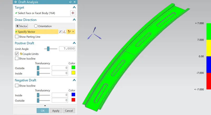
Draft analysis of Rear Roof Rail:
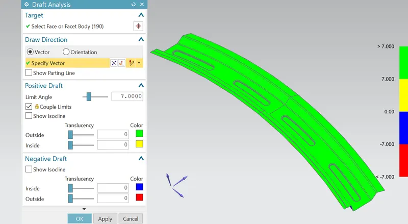
Draft analysis of Bow Roof Rail-1:
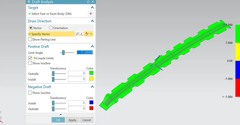
Draft analysis of Bow Roof Rail-2:
Draft analysis of Centre Reinforcement Roof Rail:
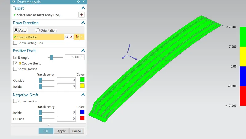
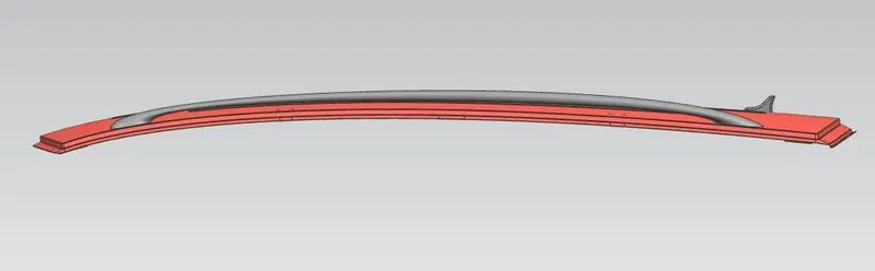
Final views of Roof
Image1
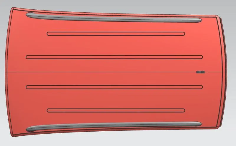
Image2
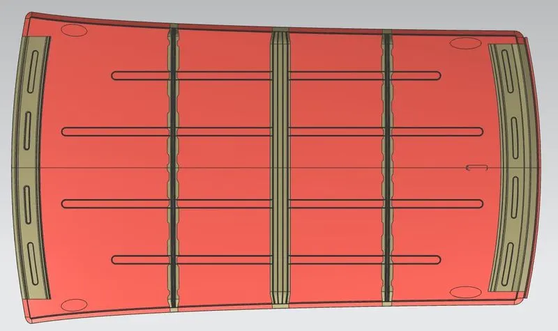
Image3
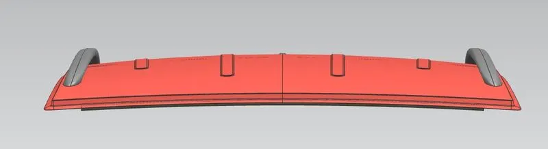
Image4
Realistic view
Conclusion:
- Roof(BIW) along with its respective stengthening reinforcement components can be successfully designed and assembled by following given master section data.
- Studied the roof curvature and examine the heat distortion and snow load criteria.As per heat distortion criteria, the roof satisfies the judgement and can withstand from deformation as per position of bow roofs.But roof does not meet the snow load condition as per the position of bow roofs.For that I have created local embosses on roof to increase the strength effectively.
- Section inertia analysis to be carried out to check the capacity of bending strength.
- Draft analysis to be carried out to check whether the components are in positive or negative draft and it is found that all the components within positve draft.
THANK YOU