Advanced Sheet Metal Design Using NX Cad Challenge_2_Box Assembly
DESIGN OF SHEET METAL BOX ASSEMBLY USING NX-CAD
Objective: The main objective of this project is to design the box assembly using the sheet metal workbench within the NX-CAD software and utilise the sheet metal features that are required for designing the sheet metal components.
Introduction: Sheet metal is a metal formed by using different forming and bending operations.It is generally made up of steel, copper, brass, aluminium etc;depending upon the strength and rigidity of the material.Also the thickness of sheet metal varies depending upon the required application.Sheet metal is used in almost all the applications like aerospace,automobile,marine,fuselages etc.
For designing the box assembly, several sheet metal features like tab,flanges,,hem flanges,unbend,rebend features etc; are required and it is provided in NX by switching to the sheet metal workbench.By using this features,to design the box assembly step by by step process as shown in the procedure followed below.Also finally the 3D sheet metal component can be converted into 2D drwaing by using drafting application which is used for providing the detailed information for manufacturing purpose in shop floor.
Design Methodlogy:
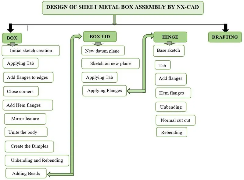
DESCRIPTION:
Box assembly mainly consists of box,lid and hinge.Each and every part can be designed by using different features like tab, flange, hem flange, mirror, unbending and rebending etc.Features used for box assembly are clearly listed below.
Features used:
Sketch:Sketch creates the 2D drawing for the model of having several sketch commands like line,rectangle,circles,arcs etc.
Tab:Tab creates a base extrude feature for the sketch of giving some thickness value along a vector direction.
Bend:Bend modifies the model by bending the material on required sides along sketch creation.
Flange:Flange creates the extension body by bending from the orginal body with required angle.
Hem Flange:Hem flange is used for folding the edge of sheet metal flange over on to itself.
Close corner: It is used for closing the two adjacent flanges, thereby extending bends and flanges.
Unite: Unite is used to combine two or more bodies into single body.
Break corner:Break corner creates the smooth rounded off faces at the edges or the faces in order to avoid the sharp corners.
Unbend:Unbend feature converts the bend model into original state model.
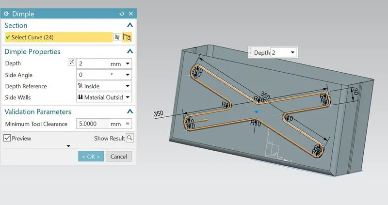
Dimple:Dimple lifts the area of the model inside the sketch for creating stamping press to the model.
Bead:Bead lifts the material along the contour of sketch that simulates a stamping tool.
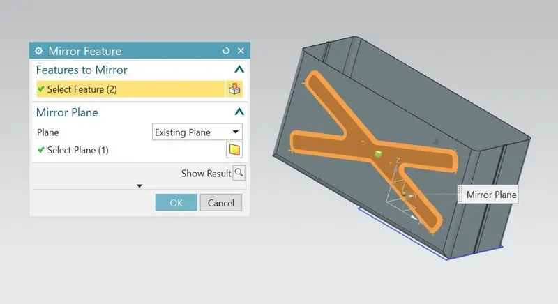
Mirror:Mirror creates a copies of bodies or features along a plane direction.
Procedure to be followed for designing sheet metal Box Assembly:
DESIGN OF BOX
- First open the NX application from the start menu and select model workbench by changing unit to millimeters..
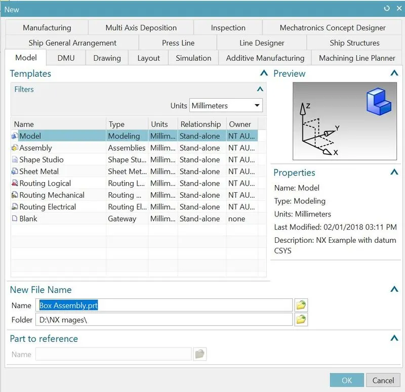
- Rename the model name to Box Assembly(.prt ) and assign the folder to save the file destination as shown below.
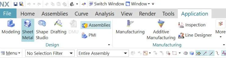
- After opening the user interface,select the sheet metal ribbon from the application tab as shown below.
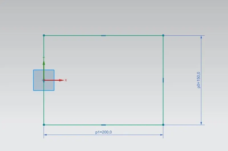
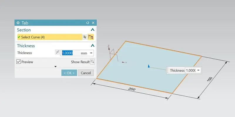
- Create a new sketch on the XY plane and draw the rectangle as center from the origin with length 200 mm and width 150mm.
- Exit from the sketch.
- Select the tab for creating base extrude to the rectangle profile and give the thickness as 1mm.
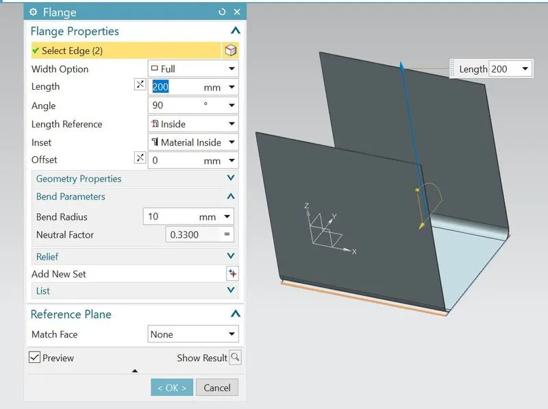
- Select flange and apply at the two sides as shown.
- Change the length to 200mm and bend radius 10mm.
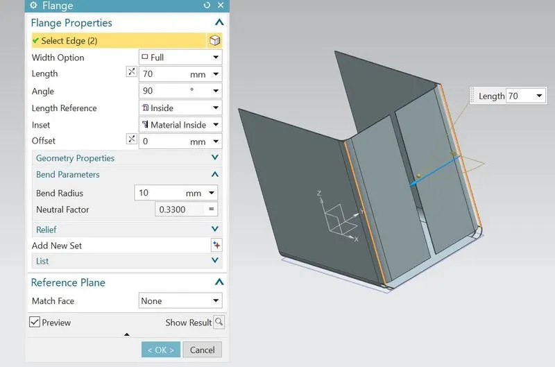
- Select flange and apply at the two sides as shown.
- Change the length to 70mm and bend radius 10mm.
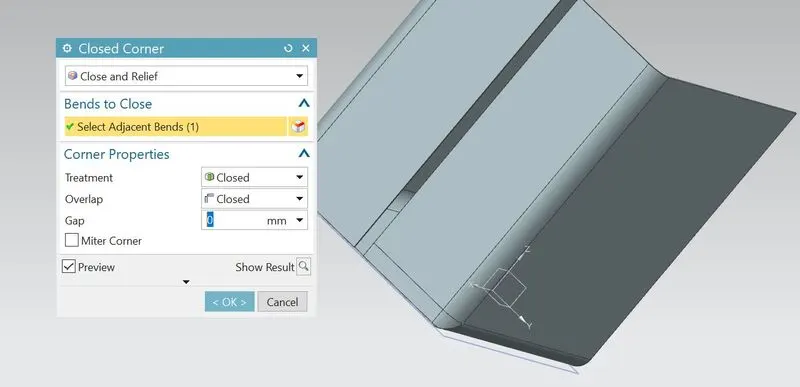
- Close the two adjacent corners by using closed corner feature and change the type as close and relief.
- Repeat the same step for closing other sides corner.
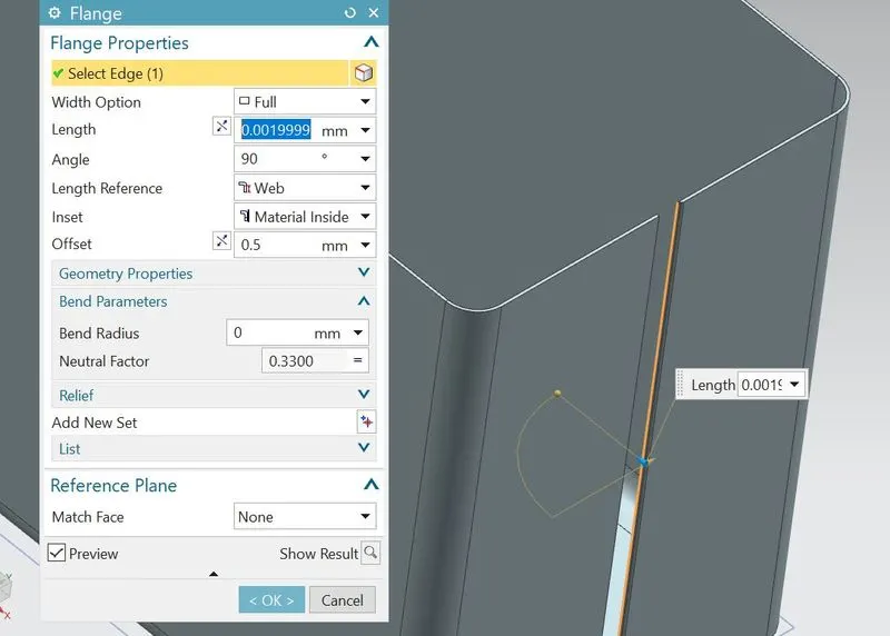
- Apply the flange at edge of length 0.02mm and bend radius 0.
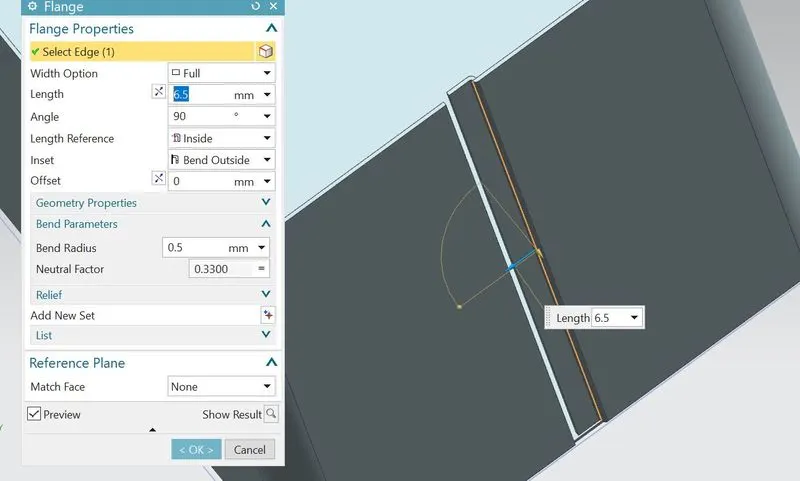
- Apply the flange at edge of length 6.5mm and bend radius 0.
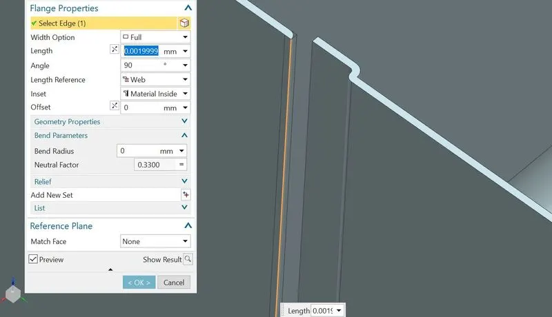
- Apply the flange at edge of length 0.02mm and bend radius 0.
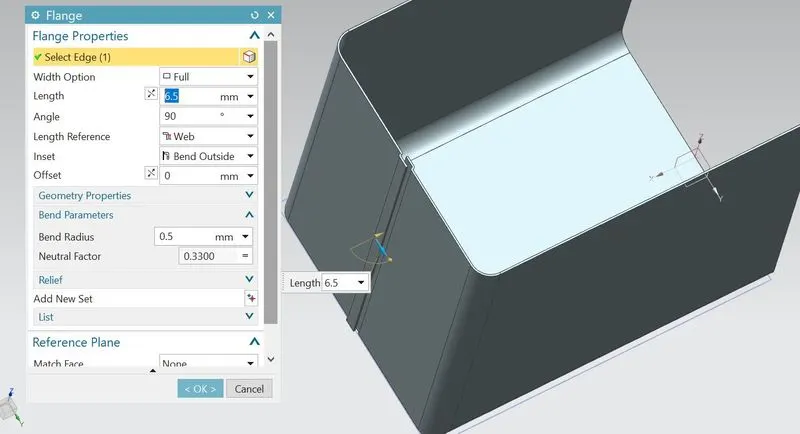
- Apply the flange at edge of length 6.5mm and bend radius 0.
- Apply the hem flange at edge of length 5mm and bend radius 0.5mm.
- Change inset type as Bend outside.
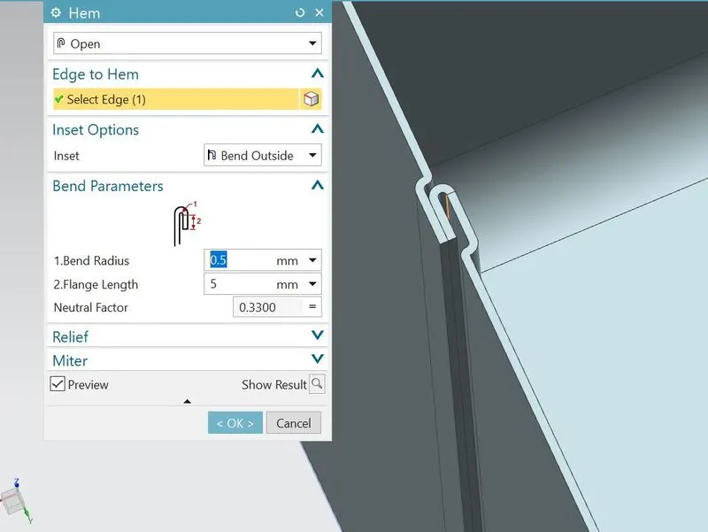
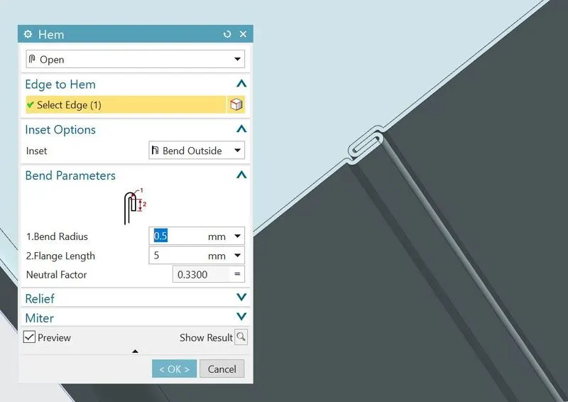
- Apply the hem flange at edge of length 5mm and bend radius 0.5mm.
- Change inset type as Bend outside.
Note:If the hem flanges are not applied properly adjust the length preferences and inset types of previous flanges.
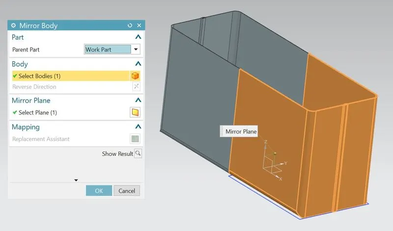
- Mirror the half body for to create the full body by selecting yz plane as mirror plane and orange colour body as body.
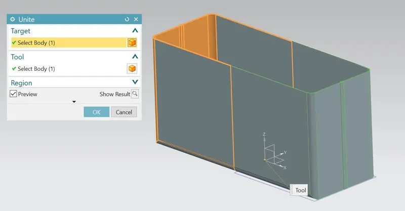
- Unite the two bodies inorder to make those two bodies as single body.
- Create the sketch on the surface of plane as shown below.
- Create the profile with required dimensions.
- Exit from sketch.
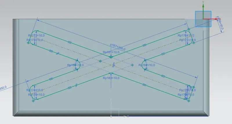
- Apply the dimple for above created sketch.
- Change the the depth to 2mm and depth reference as Inside.
- Mirror the above created feature on the other side of the body.
- Select zy plane as mirror plane.
- After the mirror is completed, the box will be like this as shown.
x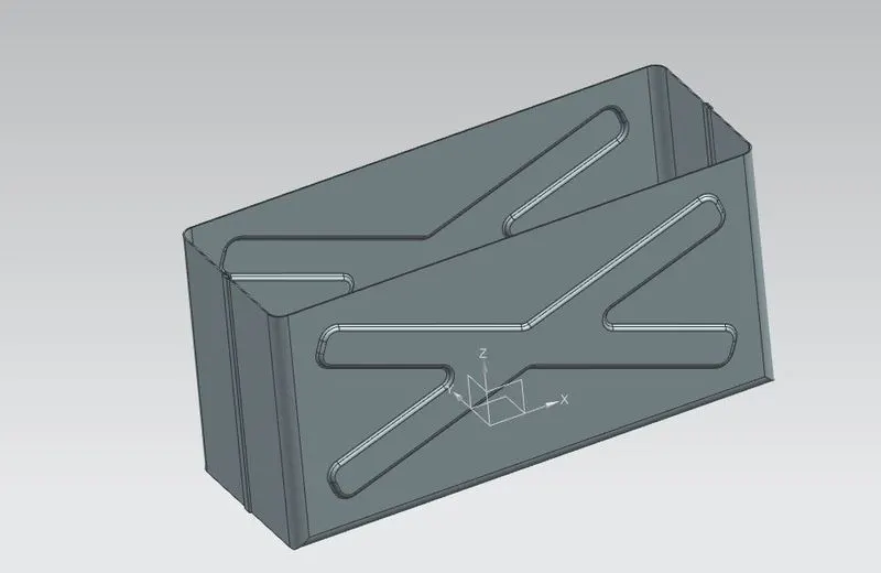
- Create the sketch on the bottom surface of the box as shown below.
- Create the profile with required dimensions.
- Exit from sketch.
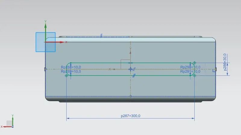
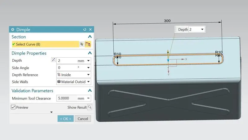
- Apply dimple to the sketch.
- Change depth to 2mm and depth reference as Inside.
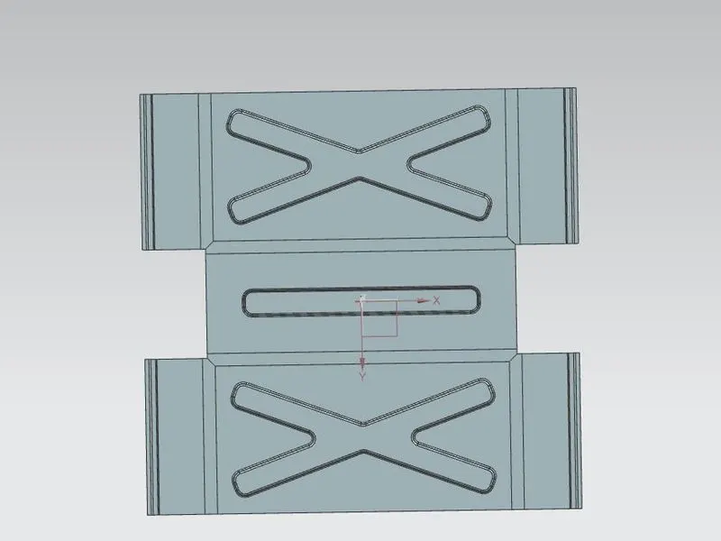
- Unbend the body as shown.
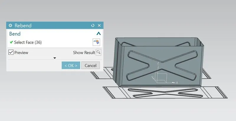
- Rebend the unbend body.
- Create the sketch on the bottom surface as shown.
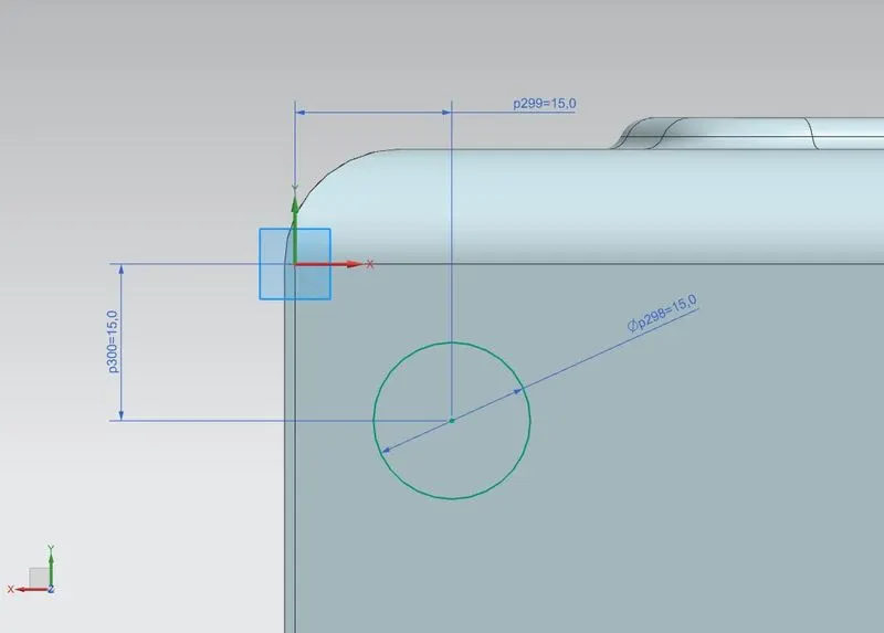
- Create the bead for above created sketch.
- Change depth as 2mm and die radius as 2 mm.
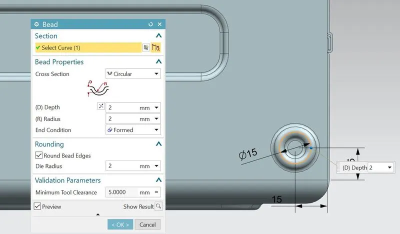
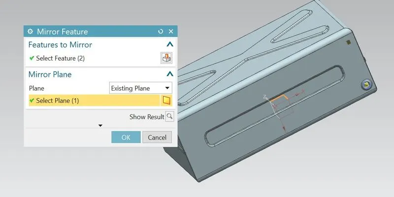
- Mirror the bead on other side as shown.
- Select the xz plane as mirror plane and bead along with sketch as mirror feature.
- Mirror the beads on other side as shown.
- Select the yz plane as mirror plane and bead,mirror bead as mirror feature.
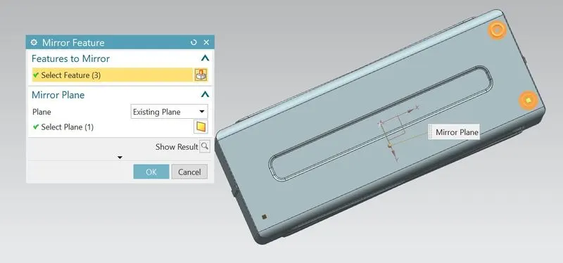
- once the mirror of beads is completed the box will be like this.
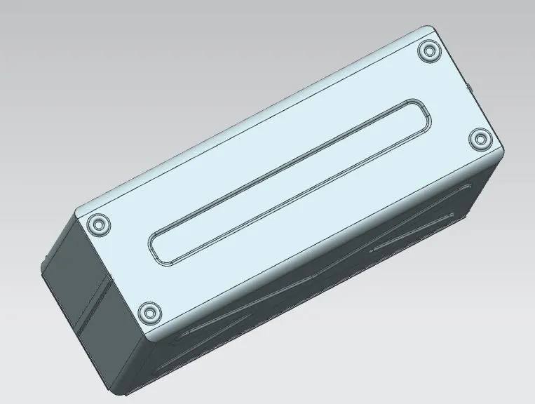
- Apply the hem at outer edge of the box as shown.
- Change the flange length as 2mm and hem type as closed.
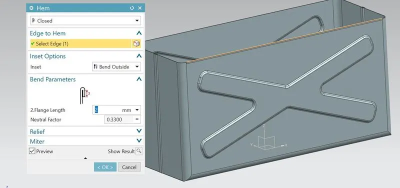
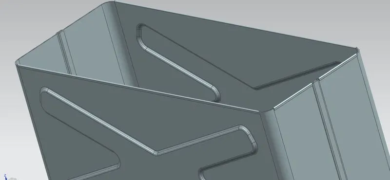
- Similarly apply the hem flanges for all remaining box outer edges.
Design of Lid
- Create a new datum plane with offset distance 203mm from xy plane.
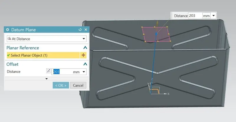
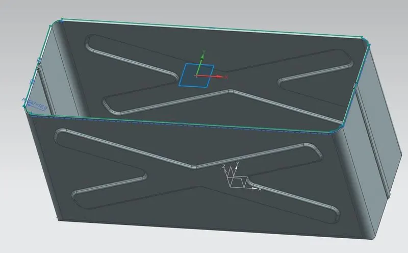
- Create sketch on new plane and convert the box outer edges as shown.
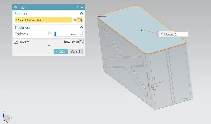
- Tab the outer edge of box of thickness 2mm.
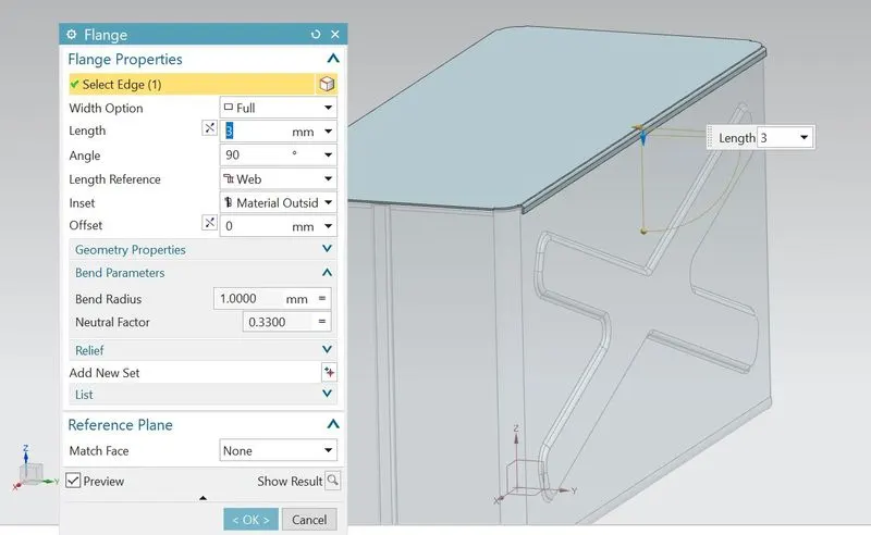
- Create the flange on one of the edge of lid of length 3mm.
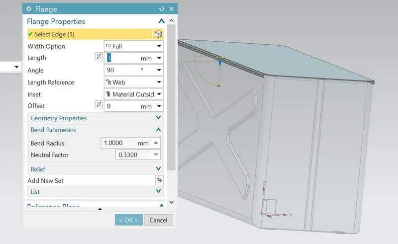
- Similarly create tab on other side of the lid.
Design of Flanges
- Create the sketch on right side surface of the box as shown.
- Draw the rectangle as per dimensions.
- Exit from sketch.
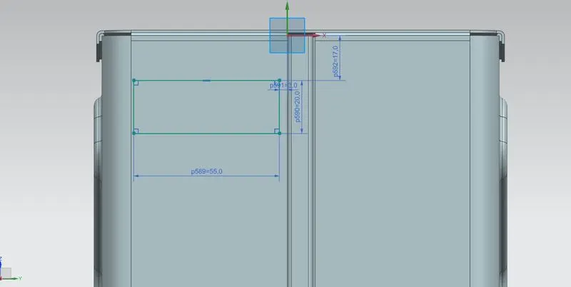
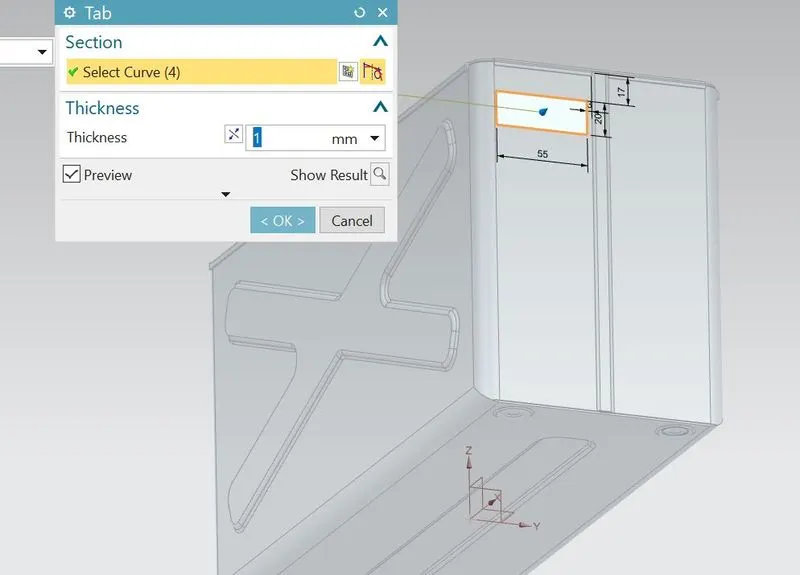
- Create the tab for rectanglular profile of thickness 1mm.
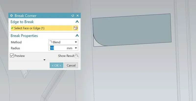
- Round the edge by using break corner of radius 10mm.
- Apply flange with 4 mm length and at an angle of 40 degrees.
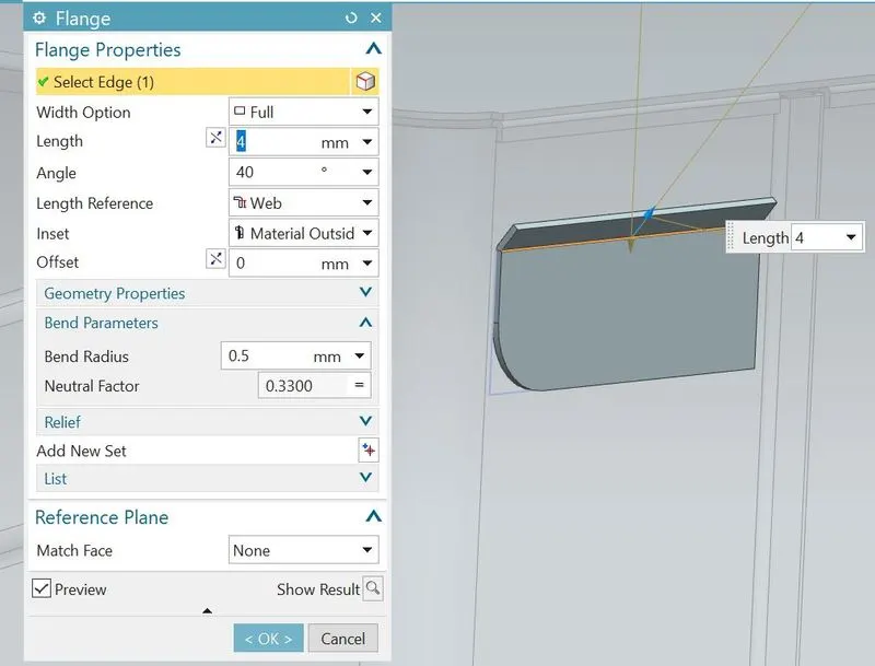
- Apply flange with 4 mm length and at an angle of 40 degrees.
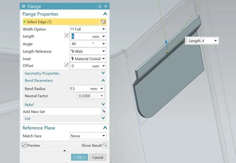
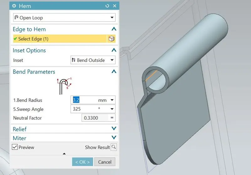
- Apply the hem at outer edge and inset type as Bend outside.
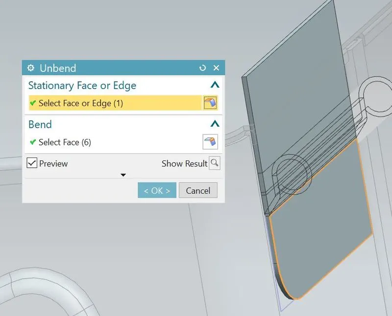
- Unbend the hinge body.
- Sketch on the surface of hinge as shown.
- Draw two rectangles with 14mm distance apart.
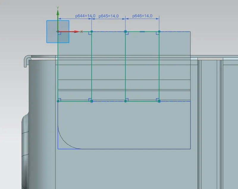
- Remove the cut out portion using Normal cutout feature.
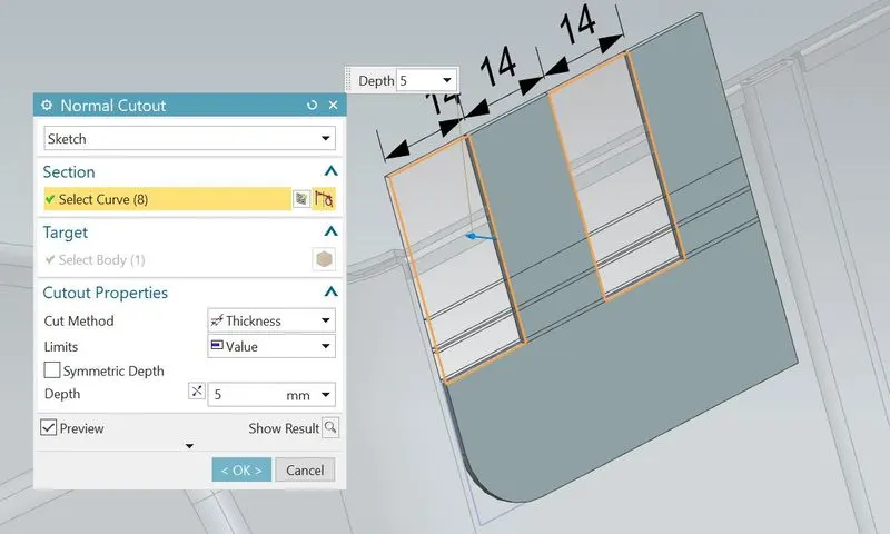
- Rebend the hinge body to original position
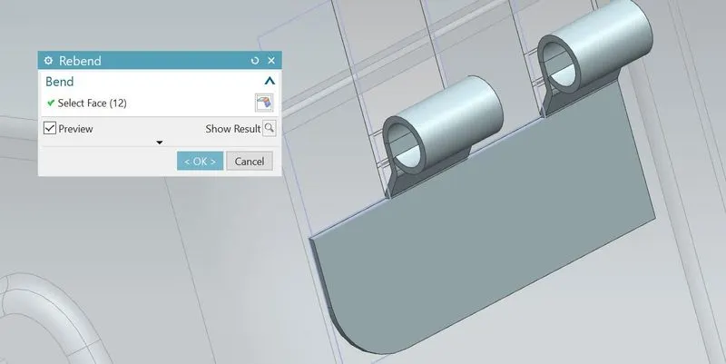
- Mirror the hinge body for creating similar hinge body on other side.
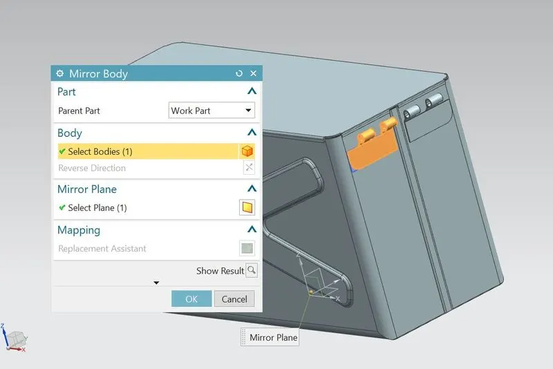
- Create the sketch on top surface of box and draw the rectangle as shown.
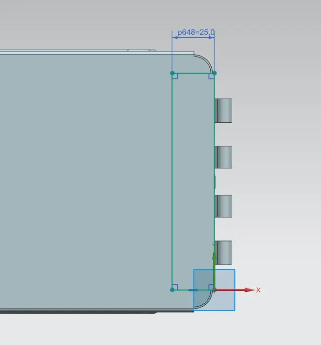
- Apply tab of thickness 1mm.
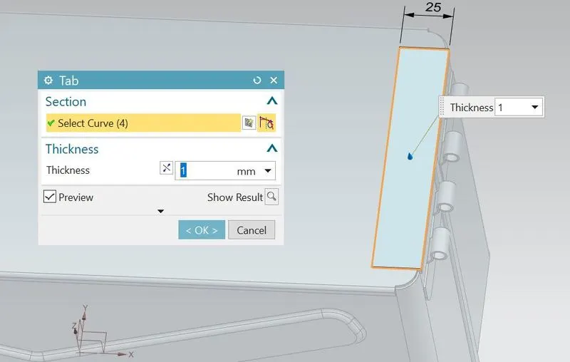
- Round the edges of radius 10mm by using break corner.
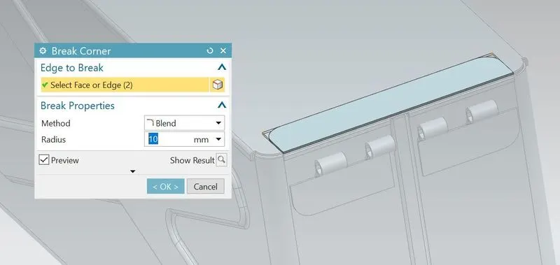
- Create the flange at the edge of bend radius 0.5mm at an angle 40mm.
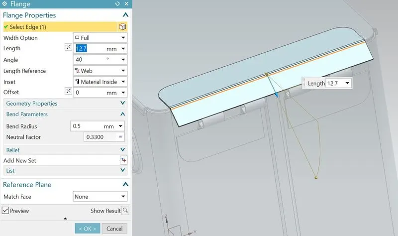
- Apply the open loop type hem flange.
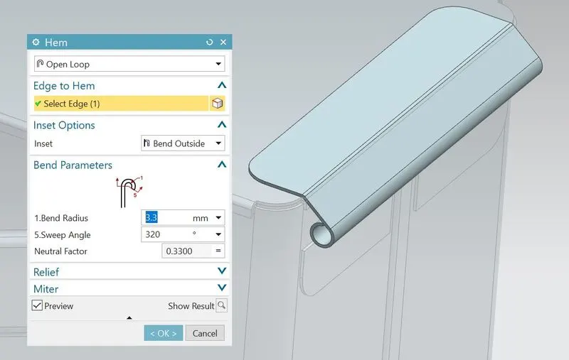
- Unbend the body.
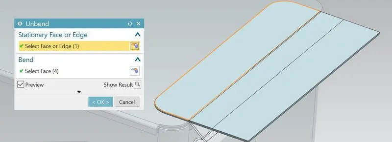
- Create the sketch on the top surface of the box as shown and draw the 4 rectangles.
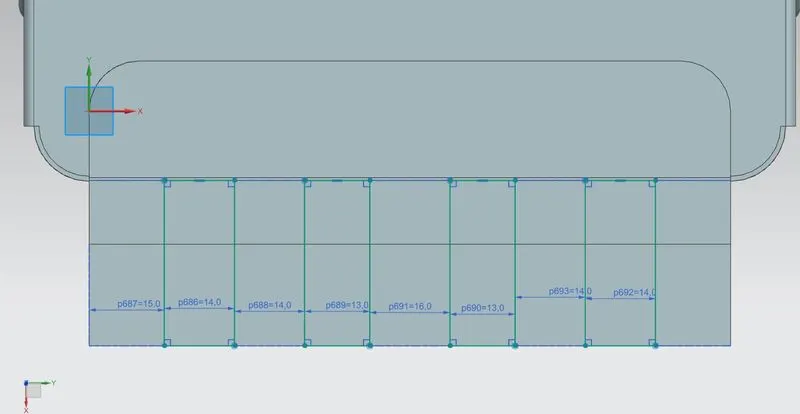
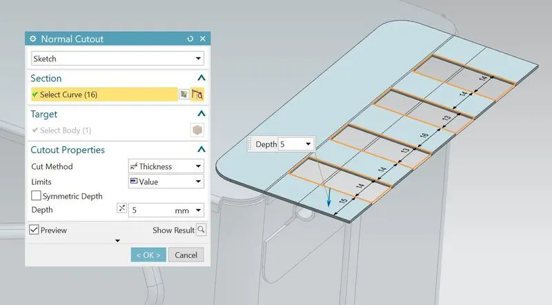
- Remove the cut out portion using Normal cutout feature.
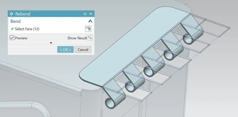
- Rebend the unbended body.
- Hence the design of sheet metal box assembly can be created a shown below.
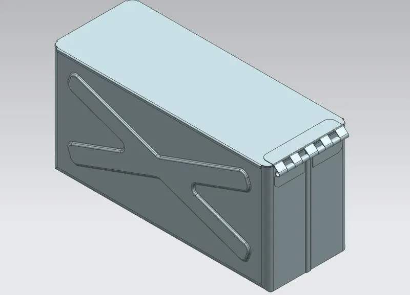
- If the box assembly to be more realistic, add the appearnces to the every part of model as shown.
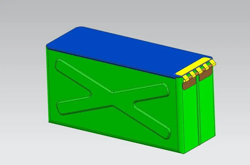
- Once the model is completed and can proceed with drafting.
- Select the drafting ribbon from the application tab.
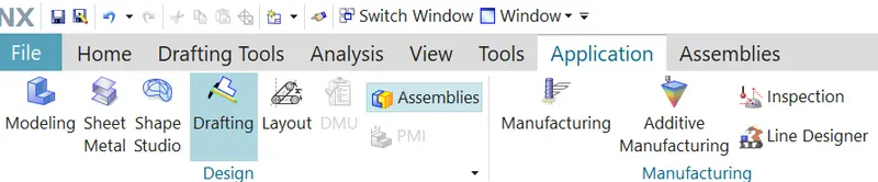
- Automatically it opens the sheet dialogue box and select the sheet size as per necessity.
- Select the base view tab and select necessary views to be drafted on sheet.
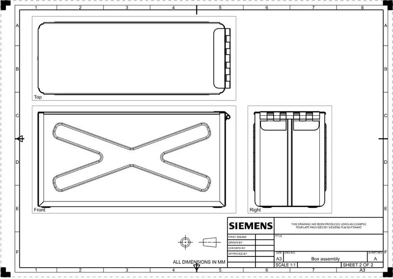
- Finally click on the save button to save the entire work.
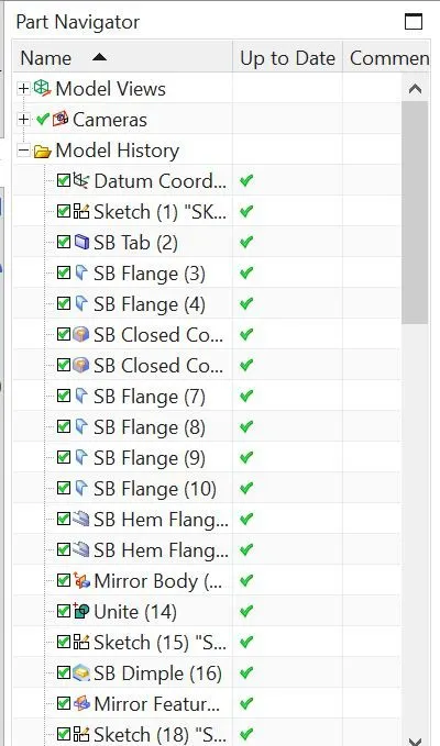
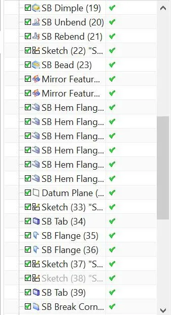
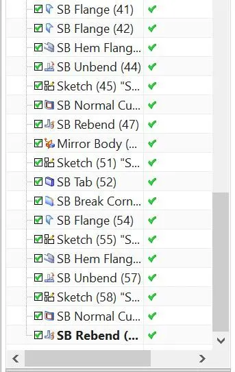
Tree diagram of part navigator:
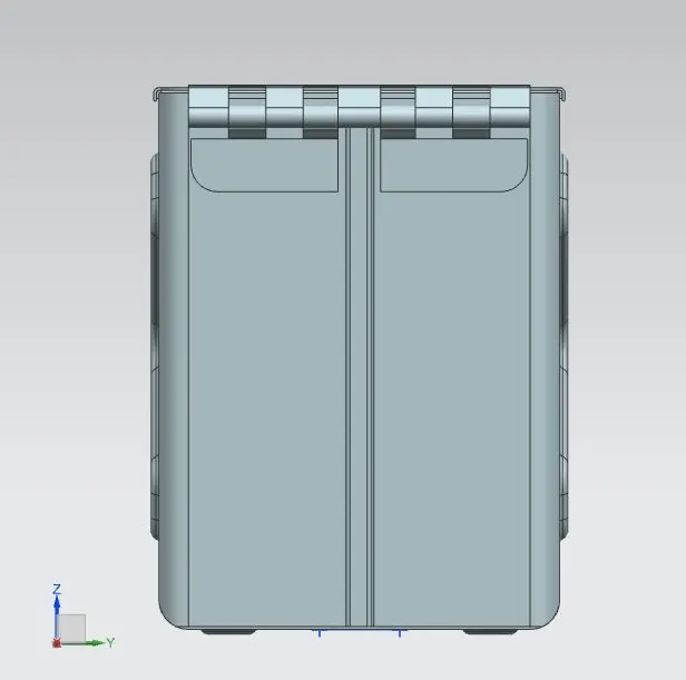
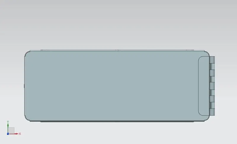
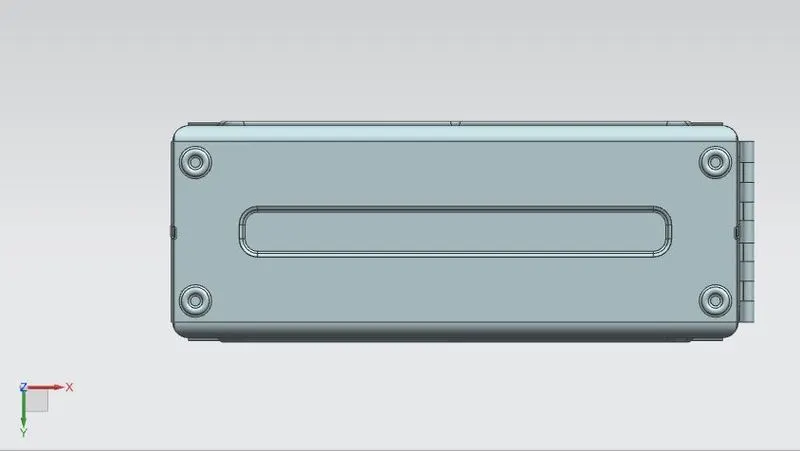
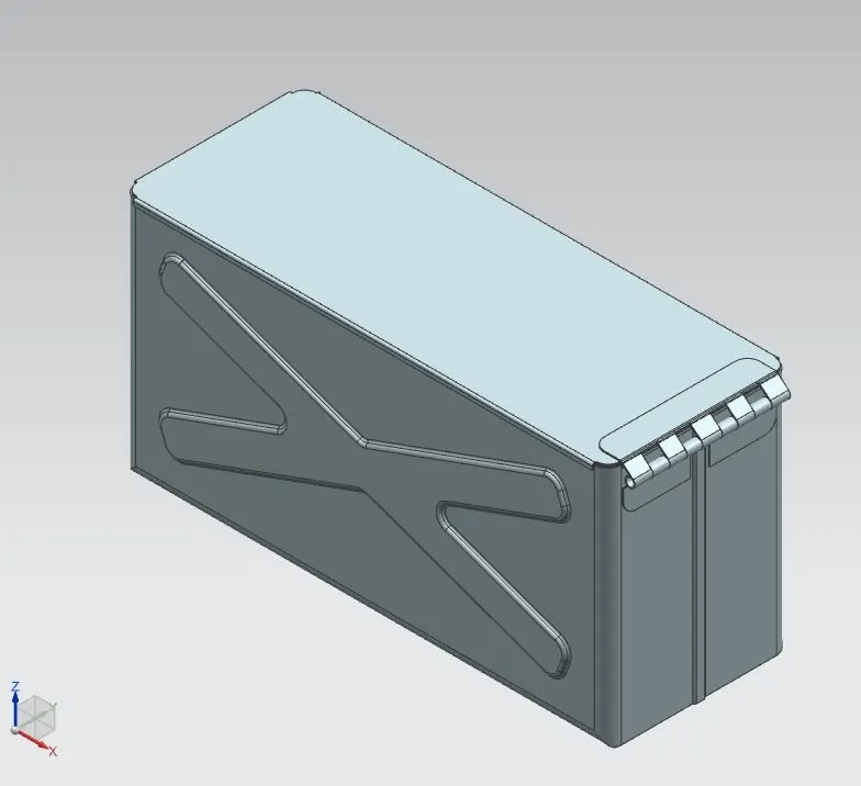
Different views of Box Assembly:
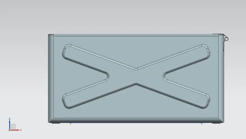
Front view
Right view
Top view
Bottom view
Isometric view
Appearance model image of Box Assembly:
Drawing Sheet image:
Conclusion:
Design of box assembly can be created as realistic by using NX sheet metal workbench and also gain a knowledge on how to use various sheet metal formation features for designing the sheet metals components..
THANK YOU