Fender Design Challenge
BIW-FENDER DESIGN
Objective:
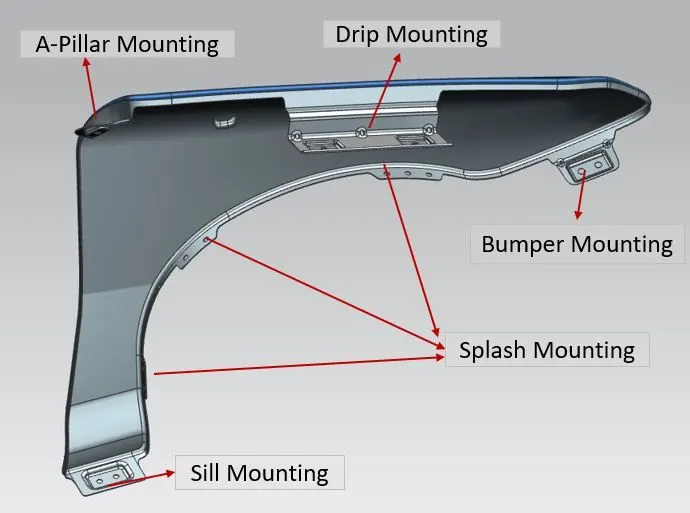
To design the BIW component -Front fender along with their respective mountings(Drip mounting,Bumper mounting, Sill mounting, Splash/Baffel mounting,A-Pillar mounting) from the given fender skin data using NX-CAD software.
Introduction:
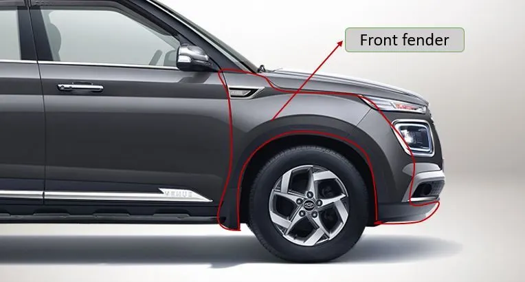
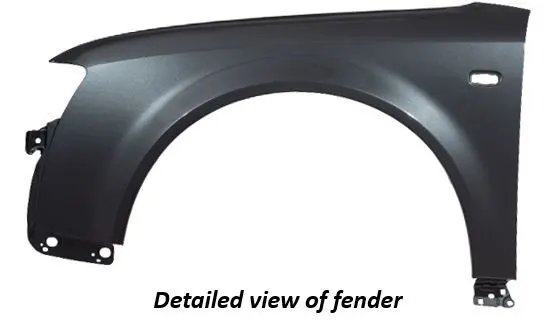
Fender is a curved portion of car's body that sit's over and houses the wheel.Its purpose is to keep mud,rocks and other debris from being thrown around by the tires.The fender not only protects the vehicle from sustaining damage from road debris but it also prevents debris from being thrown up at other vehicles and pedestrains on the road.
Types of fender:
Fender is categorized into two types-
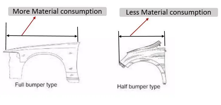
- Full bumper fender
- Half bumper fender
1.Full Bumper Fender-
Full bumper fender is the traditional type of fender commonly used in olden days.This type of fender having more material consumption as compare to present day fenders which then increases the overall weight and thus reduces performance of the vehicle.Since the material used for manufacturing of this fender type will be steel or aluminium are generally more expensive in nature.Also at a time of manufacturing,the scrap produced to be more.so wastage of such type of expensive materials will increases the material cost and also results of drastically increasing the overall cost of vehicle.So this type of fenders are not recommended in present days market.
Half Bumper Fender-
Half bumper fender is the type of fenders commonly used in present day markets.The main reason of approaching this design type is to overcome full bumper type.The material consumption is less as compare to full bumper type.The scrap produced during part production is also less and easily to perform maintainence and servicing.Also this design allows of providing space for using plastic component at bumper for absorbing shock and impact loads.So the material consumpton to produce these fenders is low which results in reduction of weight of the body and thereby icreases the overall vehicle performance.
While designing the fender of the vehicle, there are many factors to be considered -Drip area, Wheel arch area, Baffle and ORVM mount area, Gap and Flushness requirements.
Mounting regions in front fender:
Front fender can be mounted to the car body on five important major areas-
- Drip mounting area.
- Bumper mounting area
- Splash/Baffel mounting area
- Sill mounting area
- A-Pillar mounting area
Standard design requirements for fender design:
- Flat emboss should be develop for mountings.
- Must maintain 10mm flat surface for fastener holes.
- Provide proper blends to the sharp corners or sharp edges.
- Provide additional darts or beads to improve the strength for component.
- Thickness of fender should be 0.75mm.
Design Methodlogy/Procedure:
1:Drip mountig-
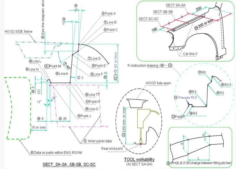
It is the area at which the fender is attached to engine housing through the fasteners.There are some considerations to be followed for designing the drip area.Here the considerations to be taken followed by the given master section.
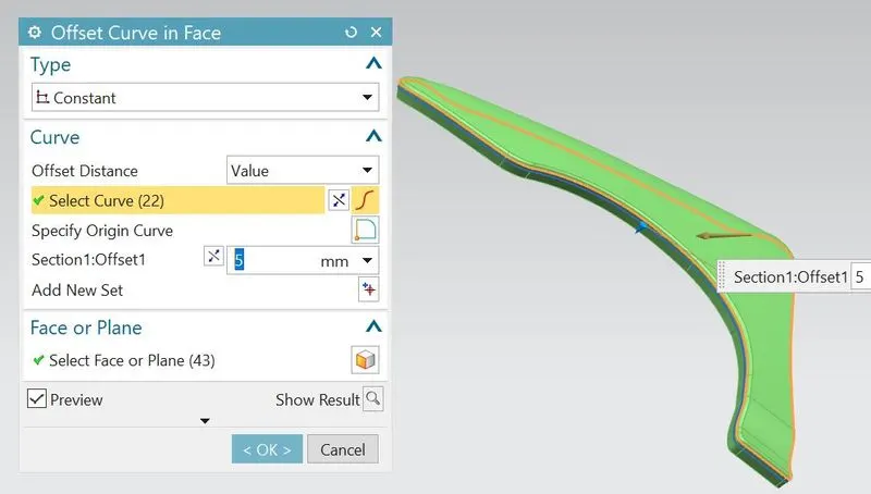
- First offset the outer edge to 5mm inside.
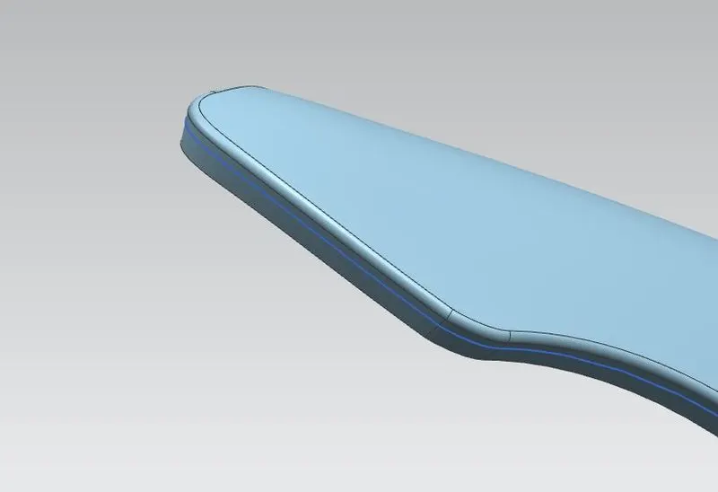
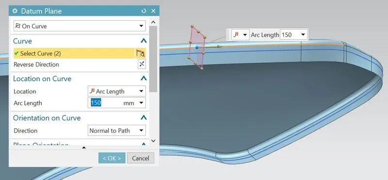
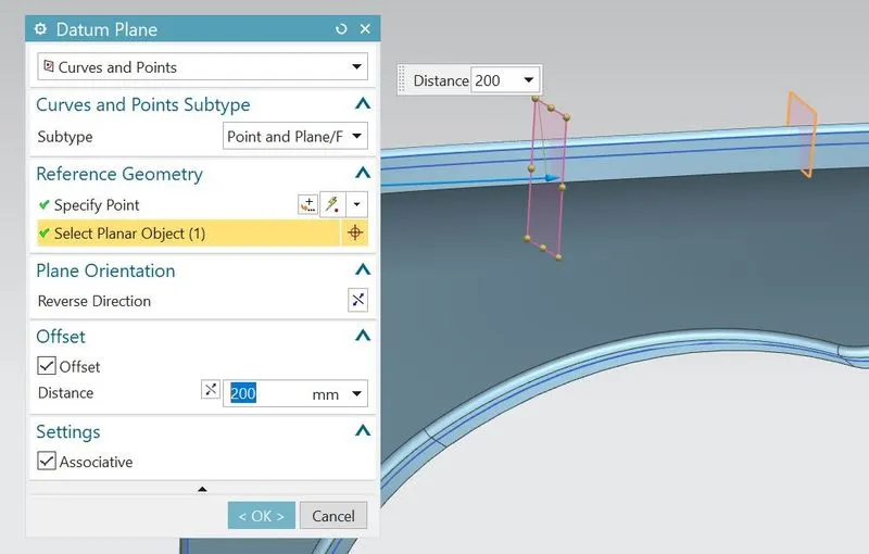
- Again offset the outer edge to 0mm.Using that offset edge,create the two datum planes .One from the front of fender at distance 150 mm for providing clearance for head lamp housing unit.Another datum plane from the back of fender at distance 200mm for providing clearance to cowl(Wiper mounting area).
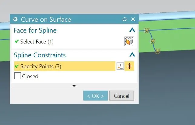
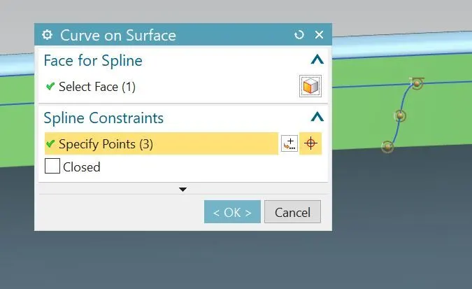
- Using curve on surface, generate smooth curves with G1 continuity for outlining the drip region.
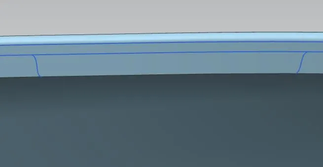
- Using trim sheet feature,remove the excess sheet surface of excluding drip region.
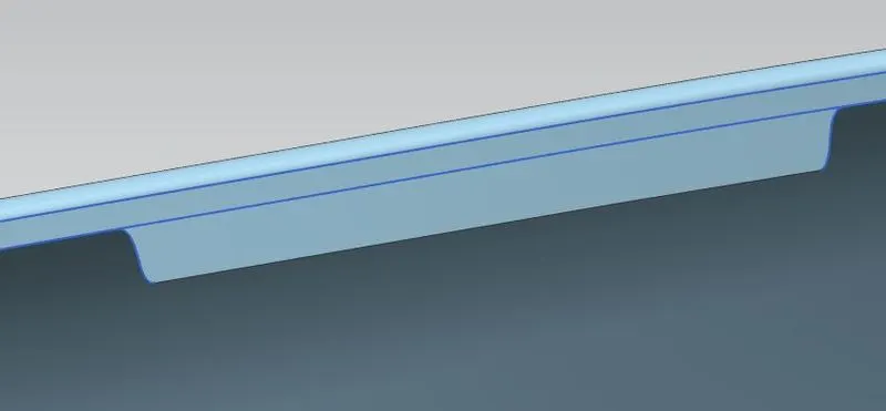
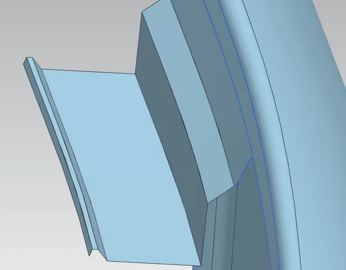
- Using law extension,create the flange of length 8mm at angle 40 deg followed by master section.
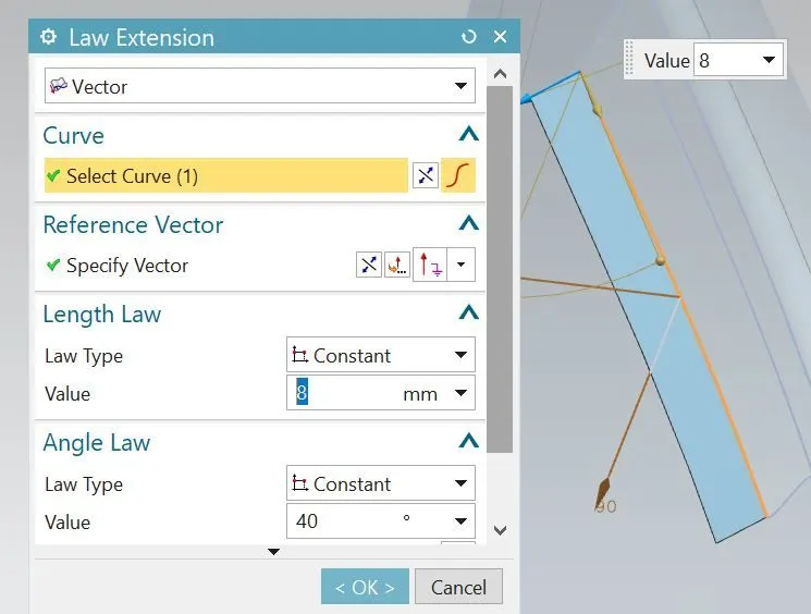
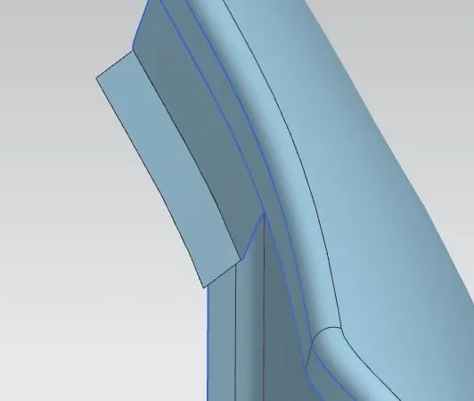
- Create the another flange from the edge of previous flange of length 17mm at angle 85 deg followed by master section.
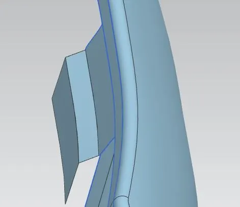
- Create the another flange from the edge of previous flange of length 25mm at angle 0 deg followed by master section.
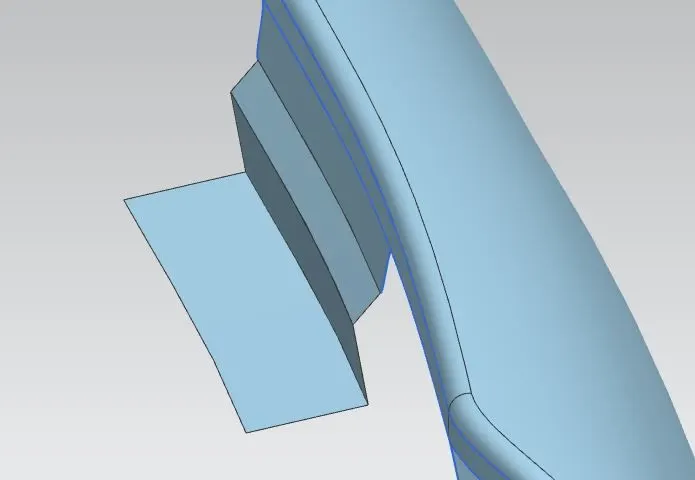
- Create the another flange from the edge of previous flange of length 4.24mm at angle 45 deg followed by master section.
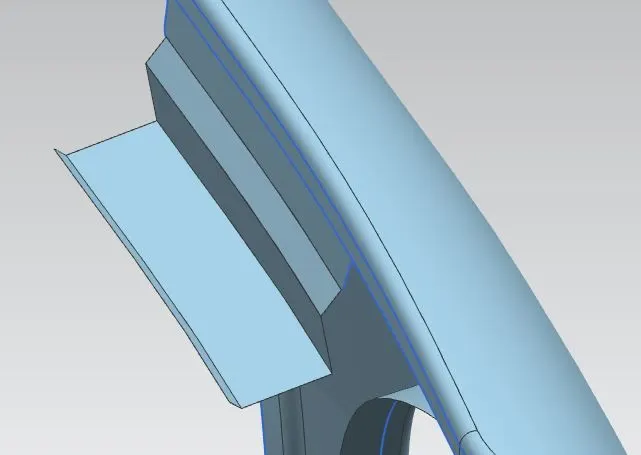
- Create the another flange from the edge of previous flange of length 1.5mm at angle 0 deg followed by master section.
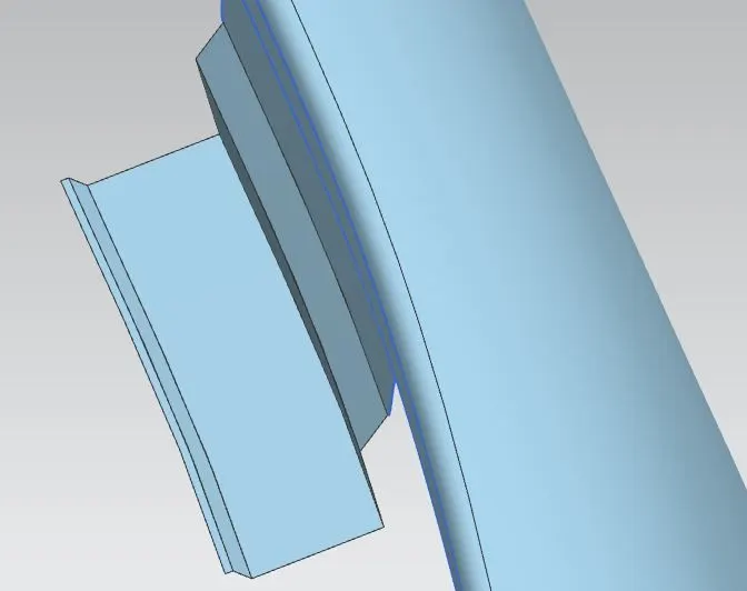
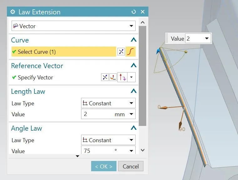
- Create the another flange from the edge of previous flange of length 2mm at angle 75 deg followed by master section.
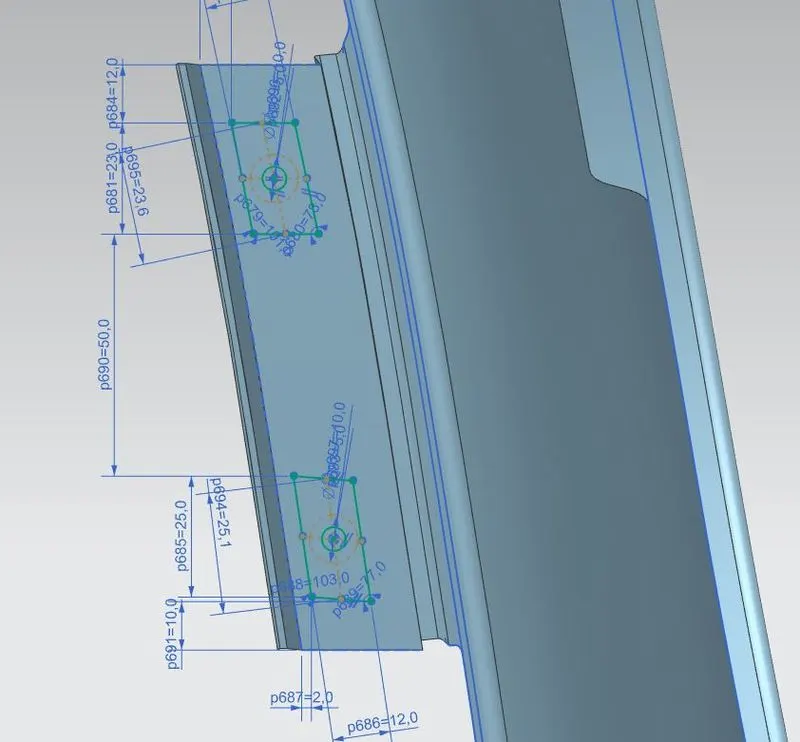
- Create the new sketch on XZ plane and draw the profiles for emboss.On the same sketch, draw the circles for mounting holes.The dotted circles in the sketch represents of having 5mm flat surface space provided for positioning of fasteners.
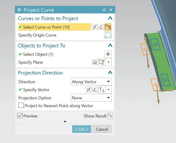
- Using the project curve feature, project the Sketched curves onto the surface.
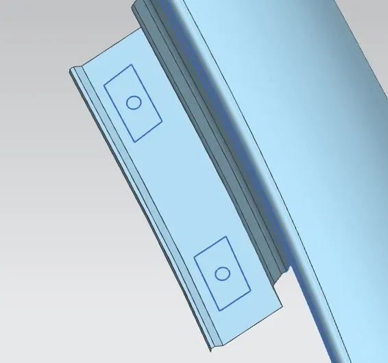
- Now create the new datum plane at the surface using curves and points.This is the datum plane helped for creating flat emboss.
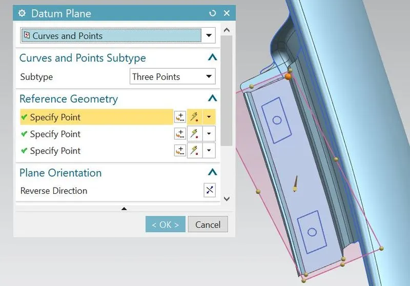
- Using the emboss feature, generate the embosses of the projected curves.Here the previous created datum plane is used as end cap geometry for creating flat surface emboss instead of embossing from surface face.At a time of mounting the fender to engine housing, the mounting section of drip must be flat for proper positioning of fasteners..If it is not flat, the fasteners tends to loose and make some localized sounds results NVH issue.
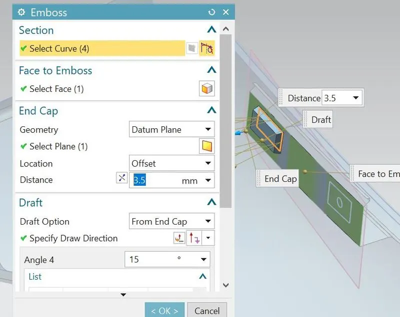
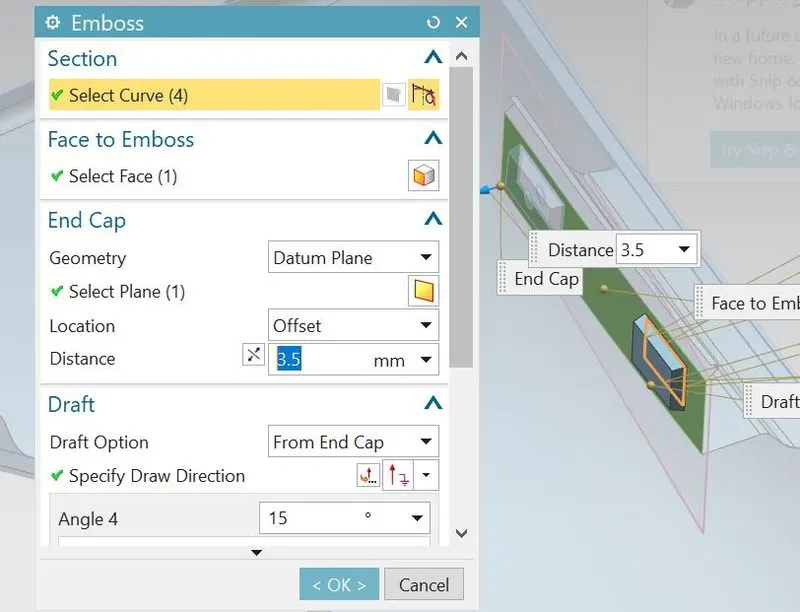
- Using trim sheet feature,remove the excess surface with in the mounting holes region.
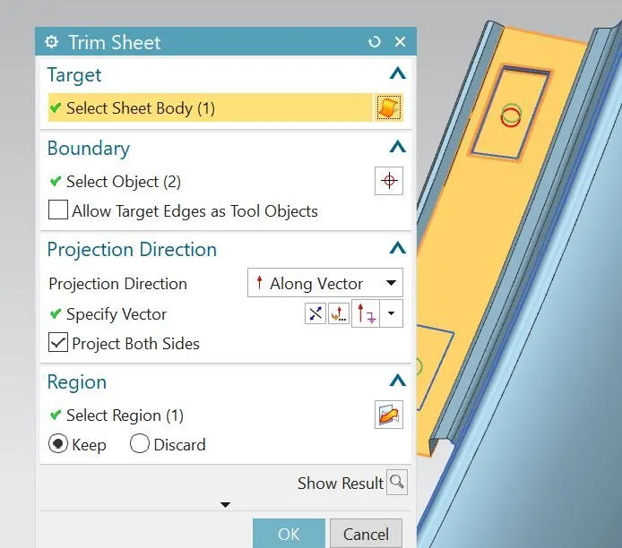
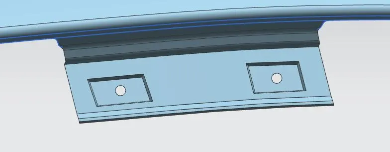
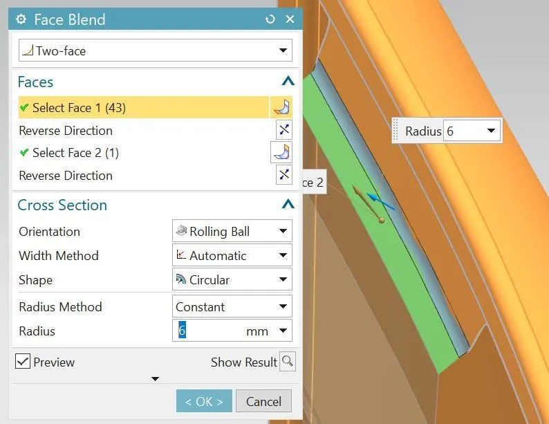
- Apply the face blend of 6mm as shown.
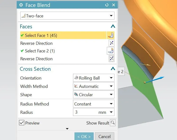
- Apply the face blend of 3mm as shown.
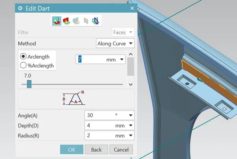
- Using dart feature, create three darts at their positions as shown.Adding these darts which helps us of providing additional strength and stiffness to the part especially at larger sections.This results of reducing the vibrations during motion and very less chances of part failure.
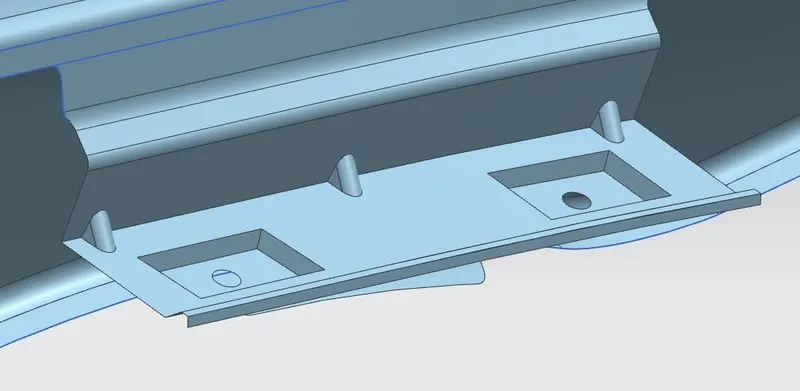
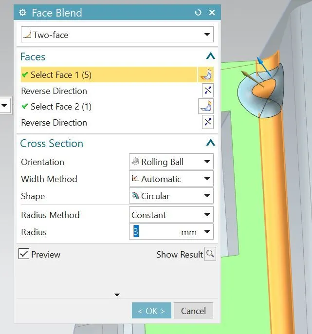
- Apply the face blend of 3 mm as shown.
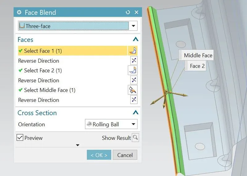
- Appy the face blend(three face blend) of selecting three faces as shown.
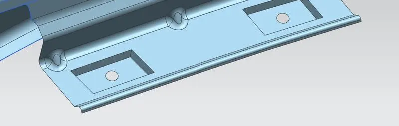
- Apply the required blends to all the embosses.
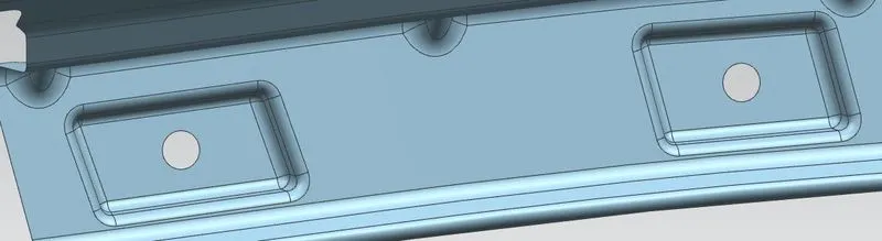
- Hence the drip mounting area can be completed.
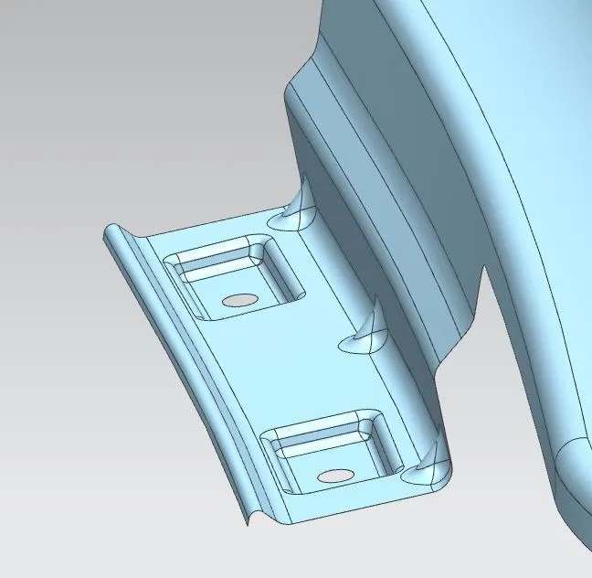
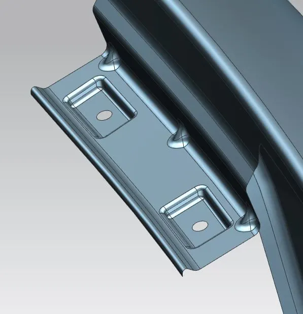
2.Bumper Mounting-
It is the area where the fender is attached to the bumper.
- Using offset curve on surface,Create the smooth curves of outlining the area of bumper from 5mm offset curve as shown.
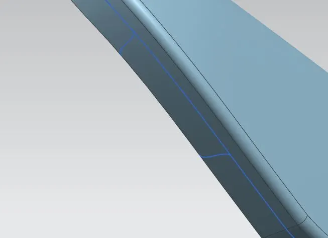
- Using trim sheet feature,remove the excess sheet surface of excluding Bumper region.
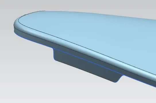
- Using law extension,create the flange of length 25mm.
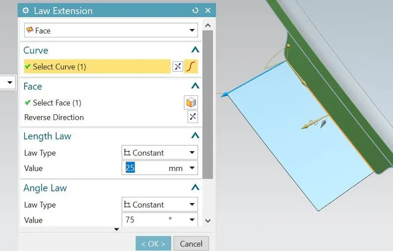
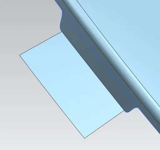
- Create the profile for emboss and project onto the surface using project curve
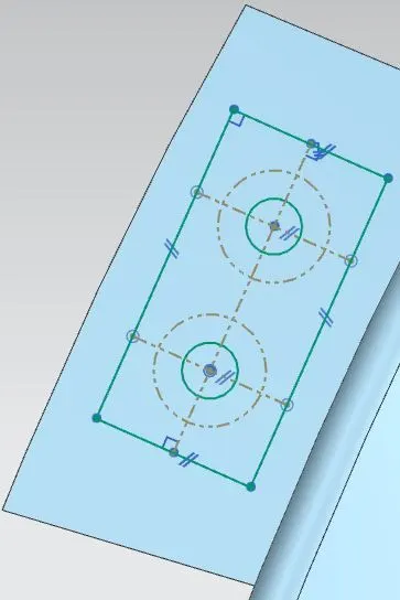
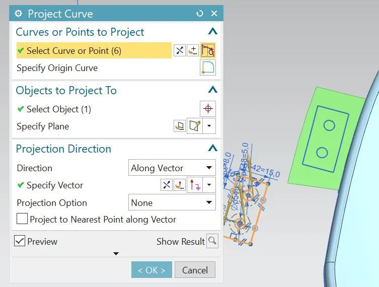
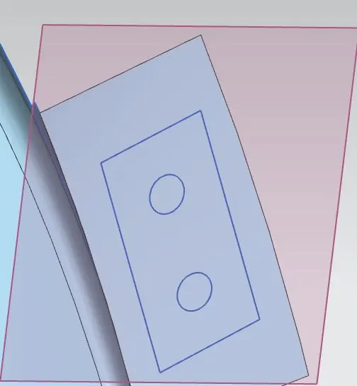
- Now create the new datum plane at the surface .This is the datum plane helped for creating flat emboss.
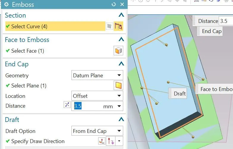
- Create the flat emboss of using previous created datum plane as end cap geometry.
- Using trim sheet feature,remove the excess surface with in the mounting holes region.

- Create two darts of improving strength to part.
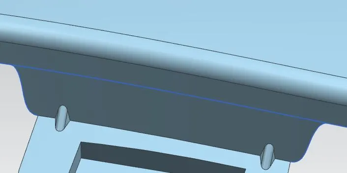
- Using Bridge curve, generate the smooth curves and remove the sharp corners.
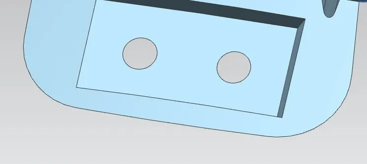
- Apply the required blends to all sharp corners or sharp edges.
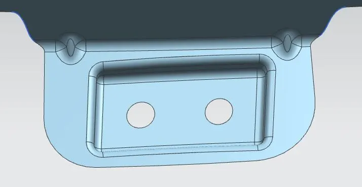
- Hence the bumper mounting area can be completed.
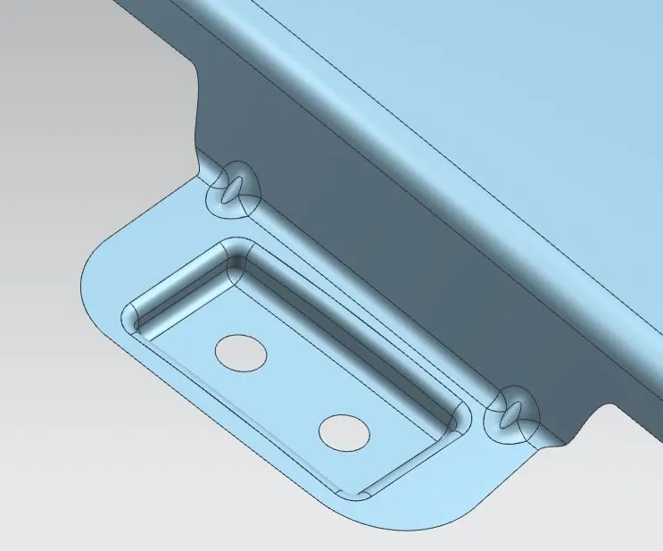
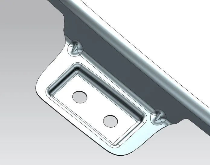
3.Baffle Mounting-
It is the area where the Baffle(prevent the debris thrown by the tire) is mounted to fender.
- Using curve on surface, create the maffler mounting regions and trim the unnecessary portion.
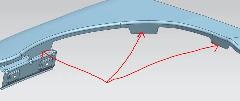
- Create the mounting holes on these regions and trim the region within mounting holes.
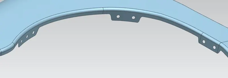
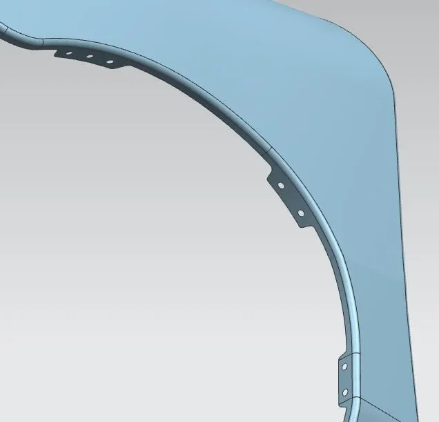
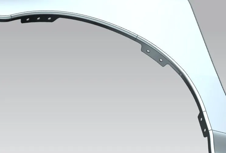
- Hence the maffler mounting area will be completed.
4.Sill Mounting-
It is the area where the fender is attached to the sill.Sill is the metal plate which is directly below the bottom of door supporting the floor and used to combine the floor and body.
- Using curve on surface, create the region for sill and trim the excess sheet.
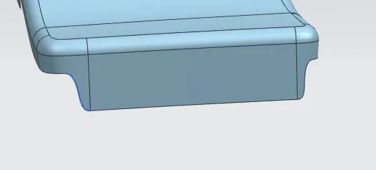
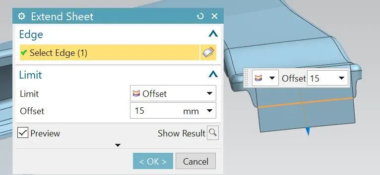
- Extend the length of sill region by using extend sheet feature.
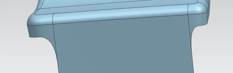
- Using bridge curve,create the smooth curves and trim the portion in order to avoid sharp surface.
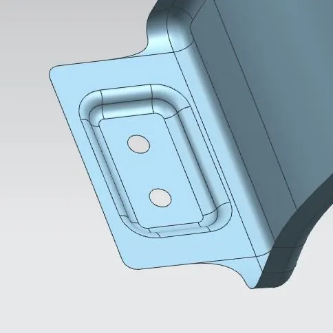
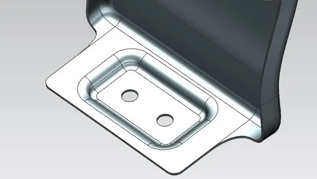
- Create the datum plane on the surface of sill region for flat emboss and sketch on the new datum plane.
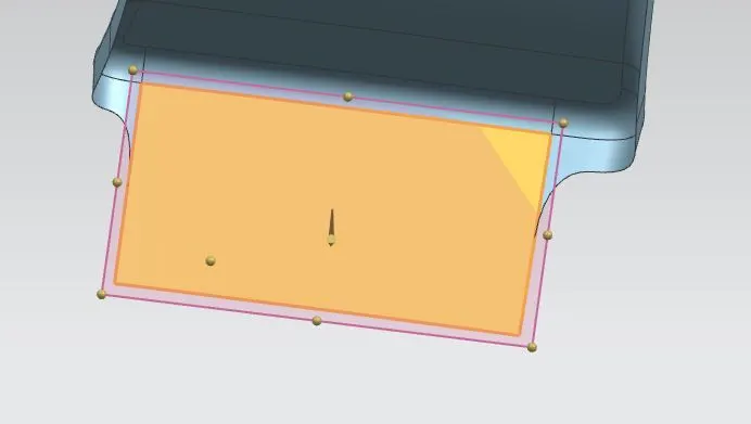
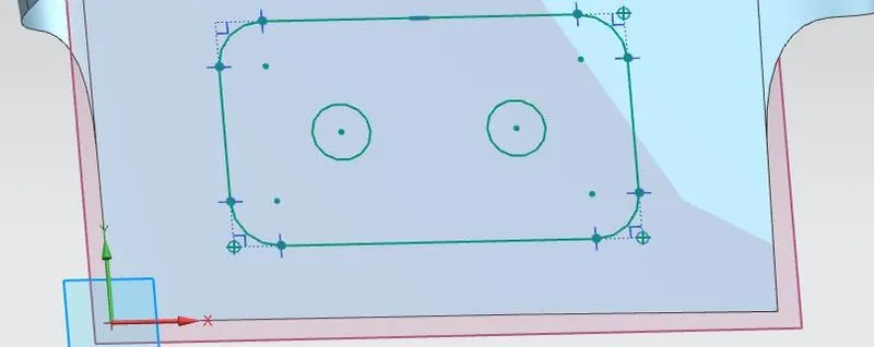
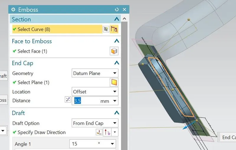
- Create the flat emboss of using previous created datum plane as end cap geometry.
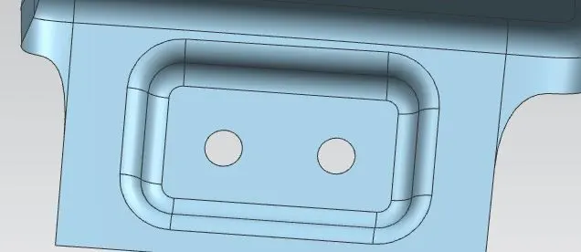
- Trim the region for mounting holes using trim sheet feature.

- Apply the required blends to emboss for to avoid sharp corners or sharp edges.
- Using bridge curve, create the smooth curves at extreme corners in order to avoid the sharp facets.
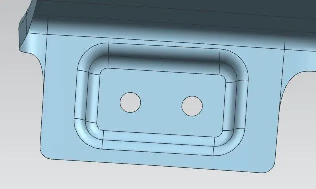
- Hence the sill mounting area can be completed.
5.A-Pillar Mounting-
It is the area where the fender is mounted to A-Pillar.A-Pillar is the structural pillar of vehicle that can holds the either side of vehicle front windscreen.
- Using curve on surface, create the A-Pillar region and trim the excess surface sheet.
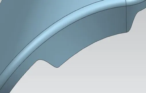
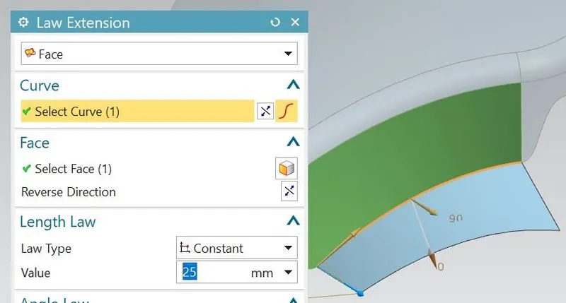
- Create the flange of length 25mm using law extension.
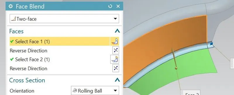
- Apply the face blend between the two faces as shown.
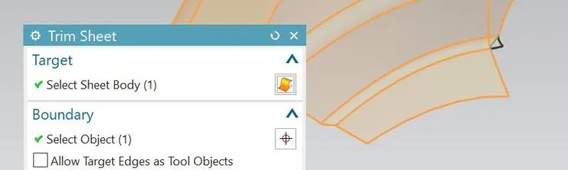
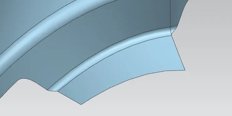
- Using trim sheet, remove the sharp surface.
- Similarly as bumper mounting,create the sketch on surface of A-Pillar region and project that curves on surface.
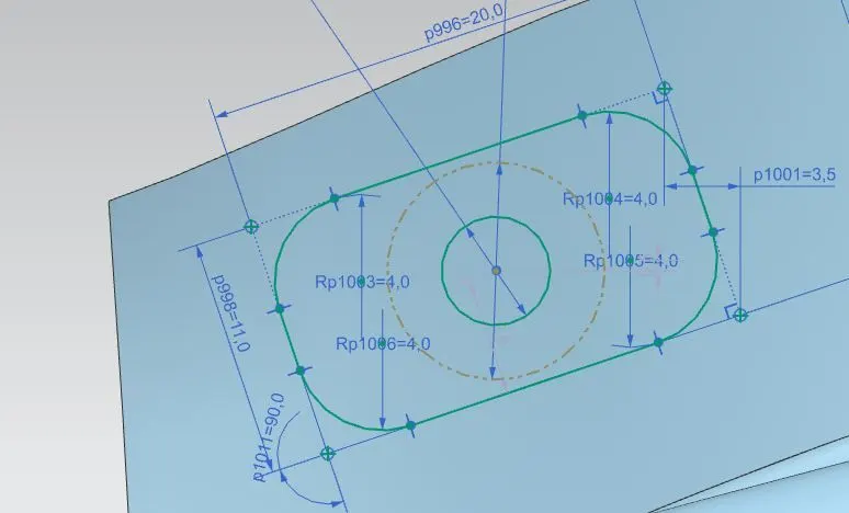
- Create datum plane for flat emboss.Using that datum plane as end cap geometry, create the flat emboss.
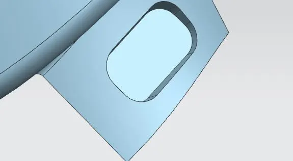
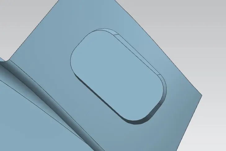
- Using trim sheet feature,remove the excess surface with in the mounting holes region.
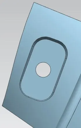
- Apply the required blends to the emboss.
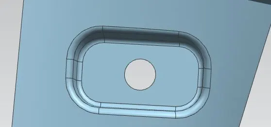
- Using bridge curve, create the smooth curves at extreme corners and trim excess portion in order to avoid the sharp facets.
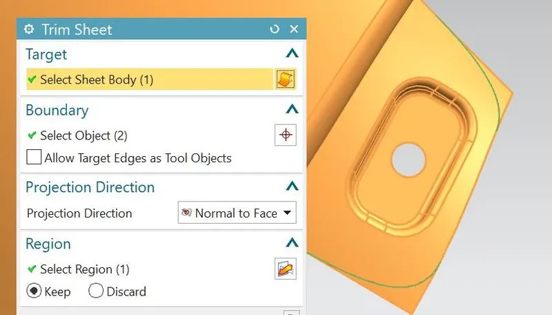
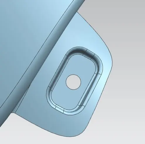
- Hence the A-Pillar mounting area can be completed.
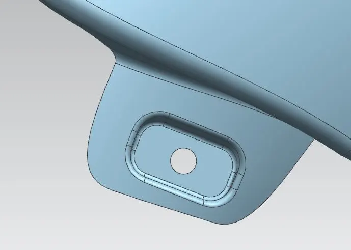
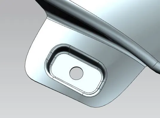
Siganl indicator light-
As we can see in many vehicles,the signal indicators is also mounted on the side of both left and right hand fenders to show an intended change of direction, whether turning left or right or moving out into traffic.So for that a signal light is also designed on the fender as shown.
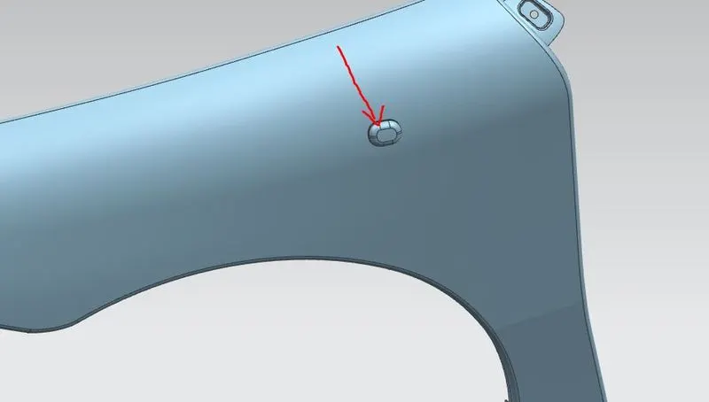
- Hence all the mounting areas can be completed.
- So using the thicken feature, give the thickness to fender sheet surface of 0.75mm.
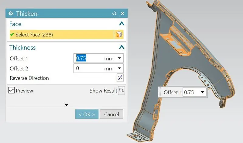
- Hide the sheet surface of fender, so that the thicken feature can be clearly visible.
- Hence the fender can be successfully designed along its mountings.
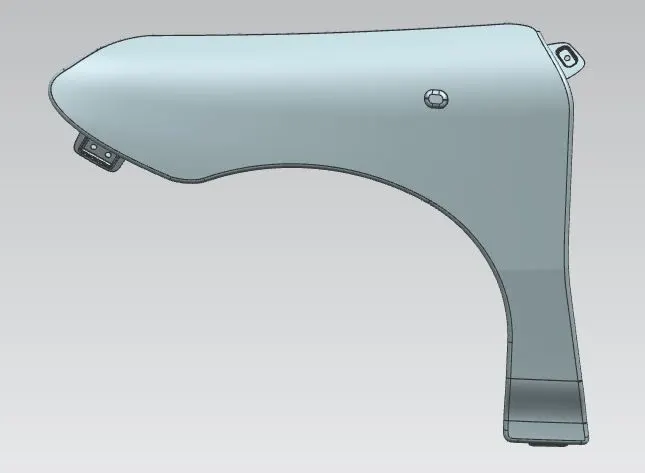
Different views of fender:
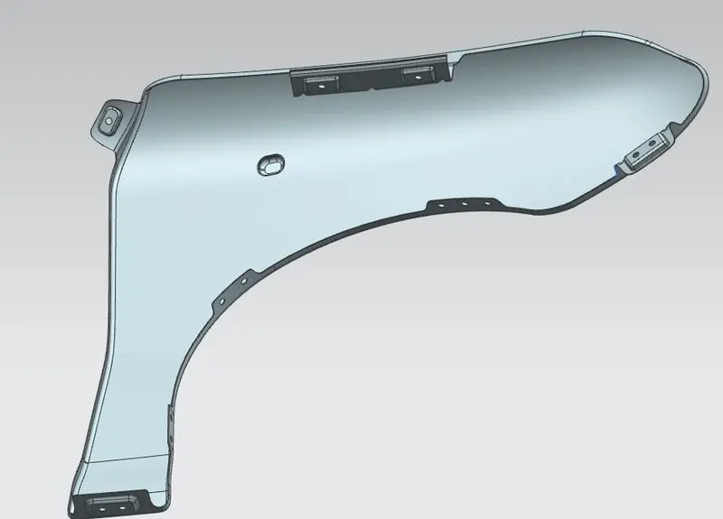
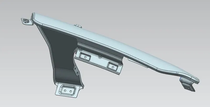
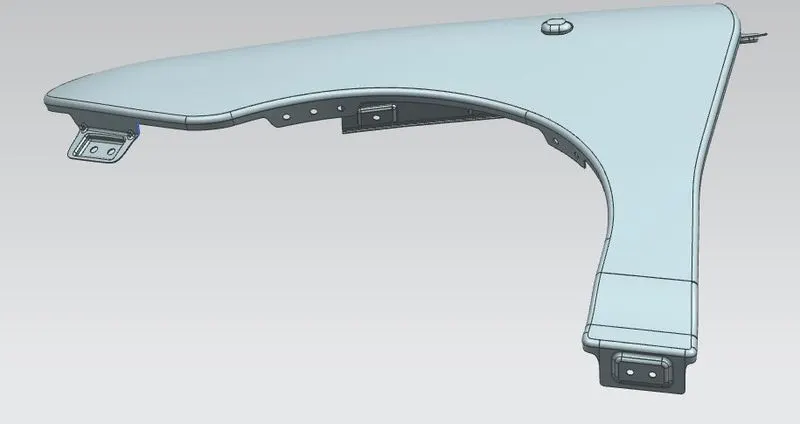
- Optionally add the appearances to give a aesthetic look for fender.
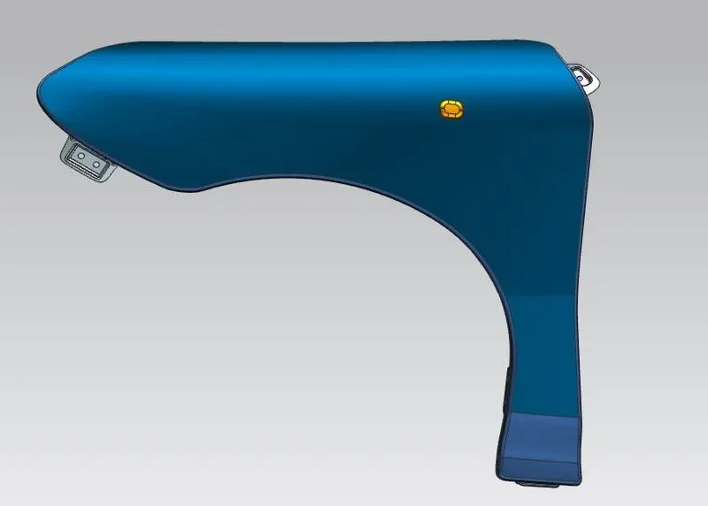
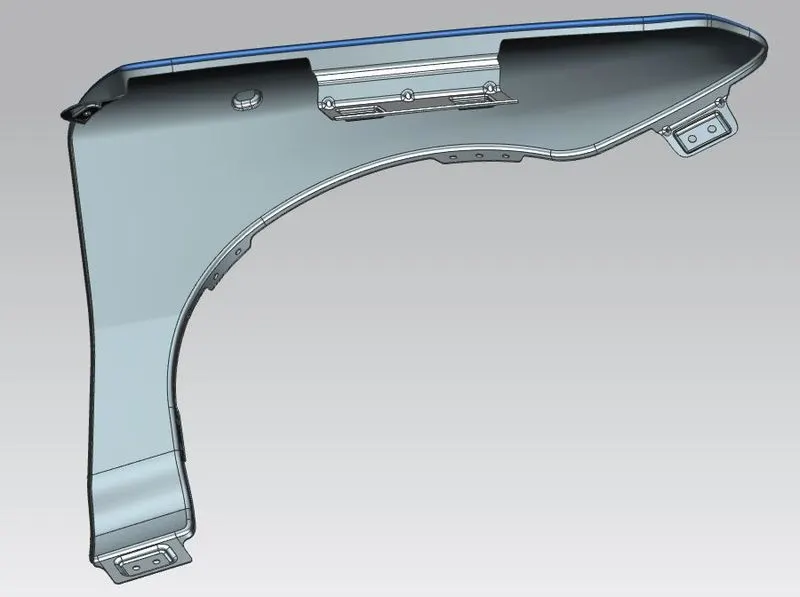
Conclusion:
Hence the fender can be successfully designed along with its mountings from the given skin data of styling team of following all the BIW standards and parameters.
THANK YOU