Advanced Sheet Metal Design Using NX Cad Challenge_1_Casing Design
DESIGN OF SHEET METAL CASING USING NX-CAD
Objective: To design the sheet metal casing component by using NX-CAD and also to gain knowledge on how to utilise the different sheet metal design features required for making the sheet metal components based on industrial purpose.
Introduction: Sheet metal is metal formed of making the base extrude feature to material into thin and thick pieces.It includes various cutting and forming operations for manufacturing the sheet metal.So here for designing the CAD sheet metal casing, using the NX-CAD software.NX was introduced by siemens organisation and it is mainly used for solid modelling,surface modelling as well as sheet metal modelling.
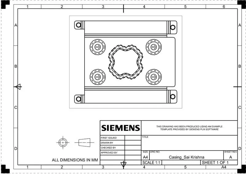
For designing the casing, several sheet metal features like tab,flanges,unbend,rebend features etc; are required and it is provided in NX by switching to the sheet metal workbench.By using this features,to design the casing step by by step process as shown in the procedure followed below.Also finally the 3D sheet metal component can be converted into 2D drwaing by using drafting application which is used for providing the detailed information for manufacturing purpose in shop floor.
Design Methodlogy:
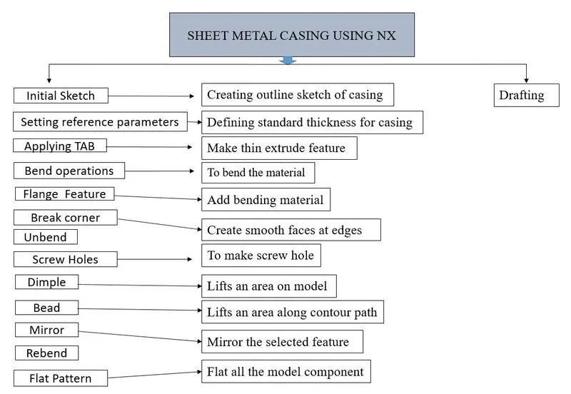
DESCRIPTION:
Features used:
Sketch:Sketch creates the 2D drawing for the model of having several sketch commands like line,rectangle,circles,arcs etc.
Tab:Tab creates a base extrude feature for the sketch of giving some thickness value along a vector direction.
Bend:Bend modifies the model by bending the material on required sides along sketch creation.
Flange:Flange creates the extension body by bending from the orginal body with required angle.
Break corner:Break corner creates the smooth rounded off faces at the edges or the faces in order to avoid the sharp corners.
Unbend:Unbend feature converts the bend model into original state model.
Hole:It adds a hole on multiple solid bodies of having several forms and screw types like countersunk,counterbored etc.
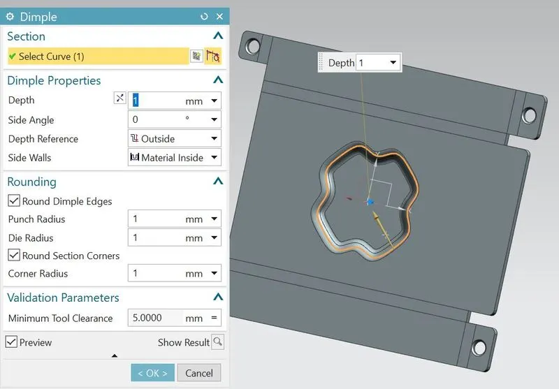
Dimple:Dimple lifts the area of the model inside the sketch for creating stamping press to the model.
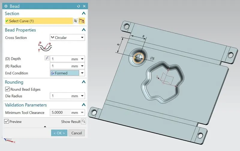
Bead:Bead lifts the material along the contour of sketch that simulates a stamping tool.
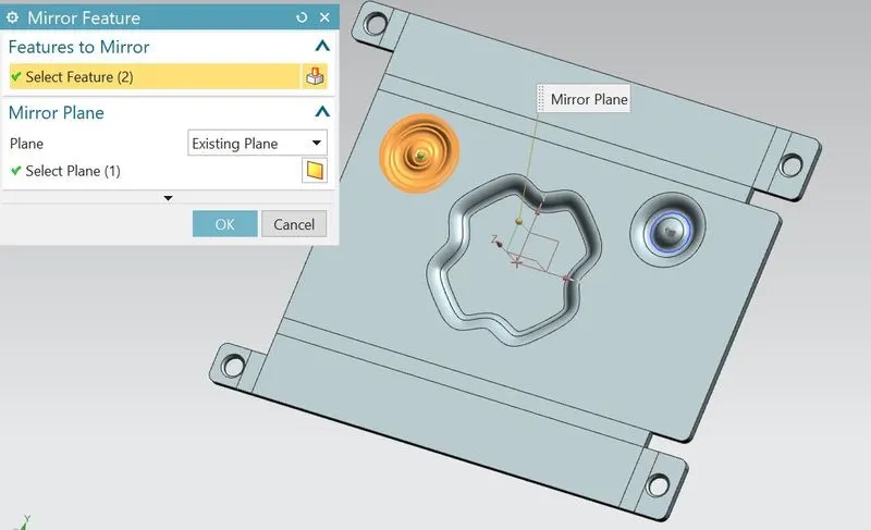
Mirror:Mirror creates a copies of bodies or features along a plane direction.
Flat Pattern:This feature creates a flat pattern from the formed sheet metal part.
Procedure to be followed for designing sheet metal casing:
- First open the NX application from the start menu and select model workbench by changing unit to millimeters..
- Rename the model name to casing(.prt )and assign the folder to save the file destination as shown below.
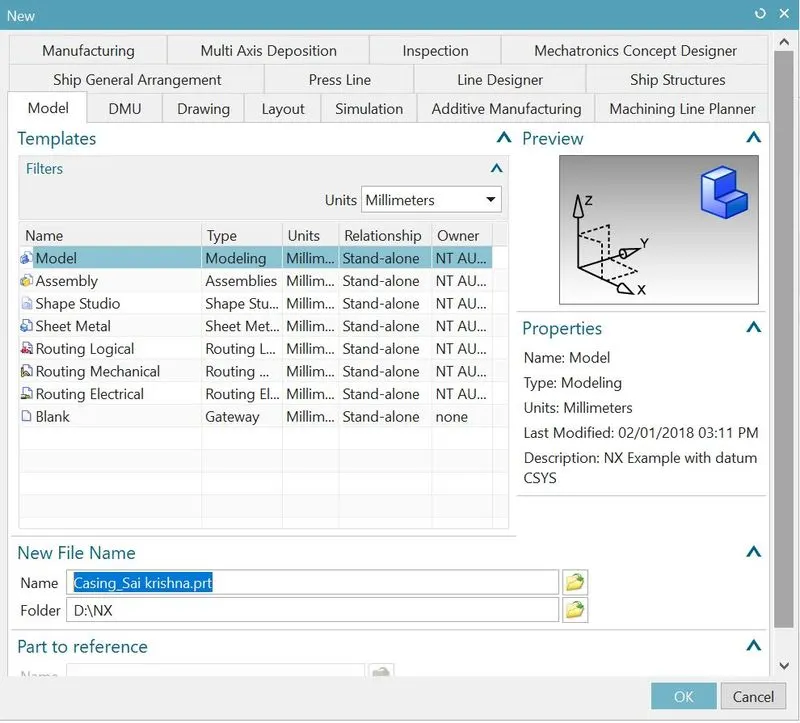
- After opening the user interface,select the sheet metal ribbon from the application tab as shown below.
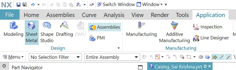
- Create a new sketch on the XY plane and draw the rectangle as center from the origin with length 60 mm and width 50mm.
- Exit from the sketch.
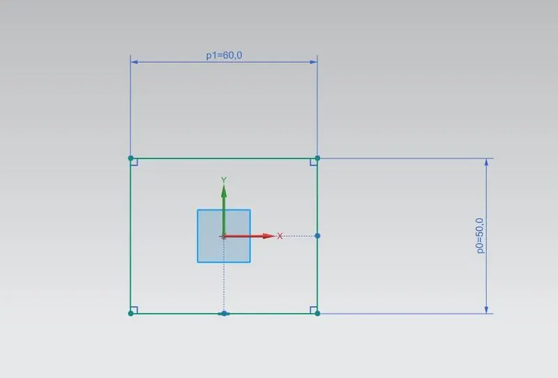
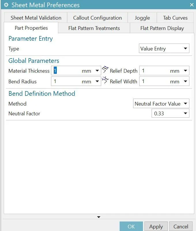
- Change the design parameters(Menu-Preferences_Sheet Metal)
- In preferences dialog box,change the global parameters to 1mm as shown below.
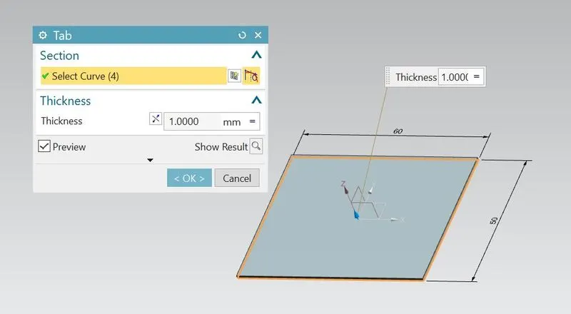
- Select tab feature for creating metal sheet to the rectangular profile and select the curve as shown below.
Note:Dont change the global value(Keep it as 1mm constant)
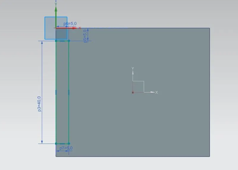
- Create the new sketch on surface of the plane as shown below.
- Draw the rectangle of length 40mm and width 5mm.
- Exit from the sketch.
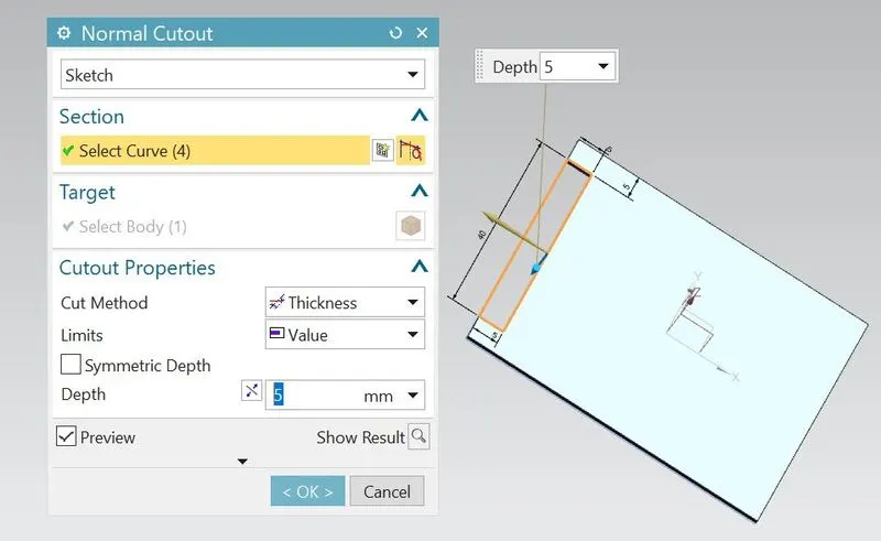
- Select normal cut out feature and select the curve as shown below.
- Click ok
- Create the new sketch on surface of the plane as shown below.
- Draw the two lines as shown below.
- Exit from the sketch.
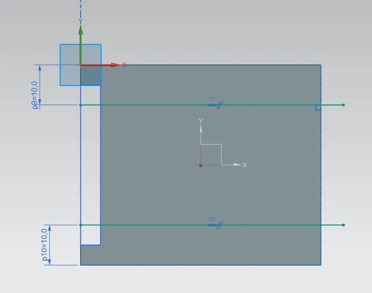
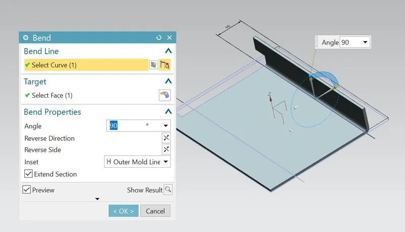
- Select bend feature and select the one line.
- Change the angle to 90 degrees.
- Click ok
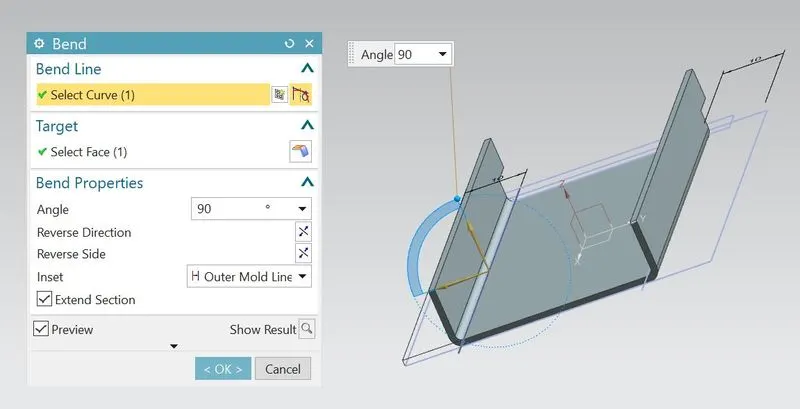
- Do the same procedure as mentioned in the above bend feature for another line.
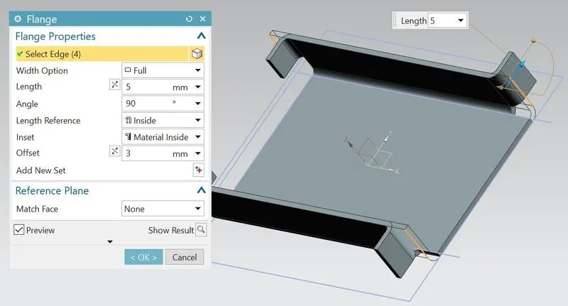
- Select the flange feature and select the 4 edges as shown which is indicated in orange colour.
- Chang the length to 5mm.
- Click ok.
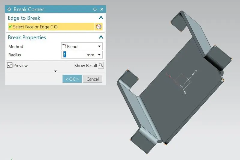
- Select the break corner feature and select all the corner edges as shown which is indicated in orange colour.
- Change radius to 1mm and click ok.
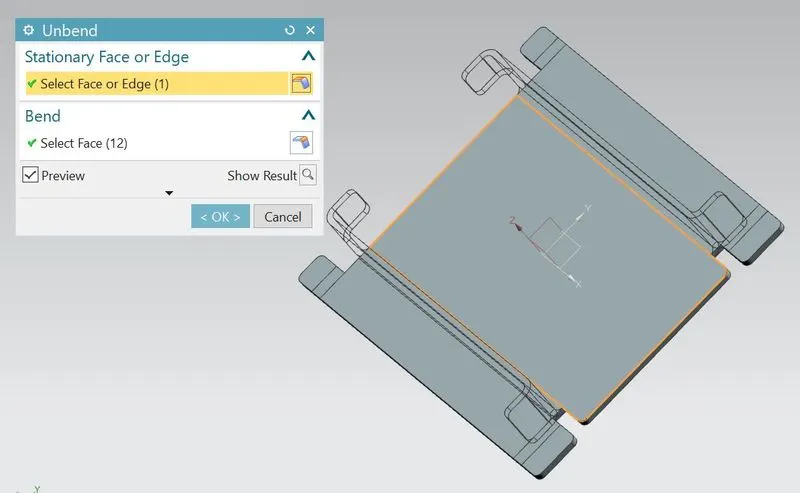
- Select the unbend feature.
- Select large horizontal face as stationary face and slect adjacent face as bend face.
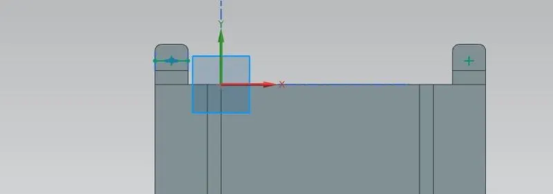
- Create the new sketch on surface of the plane as shown below.
- Draw the line in which extremities are located on middle of two line segments.
- Select point feature and click at middle of line as shown(+ symbol).
- Similarly do the same thing at bottom side.
- Exit from the sketch.
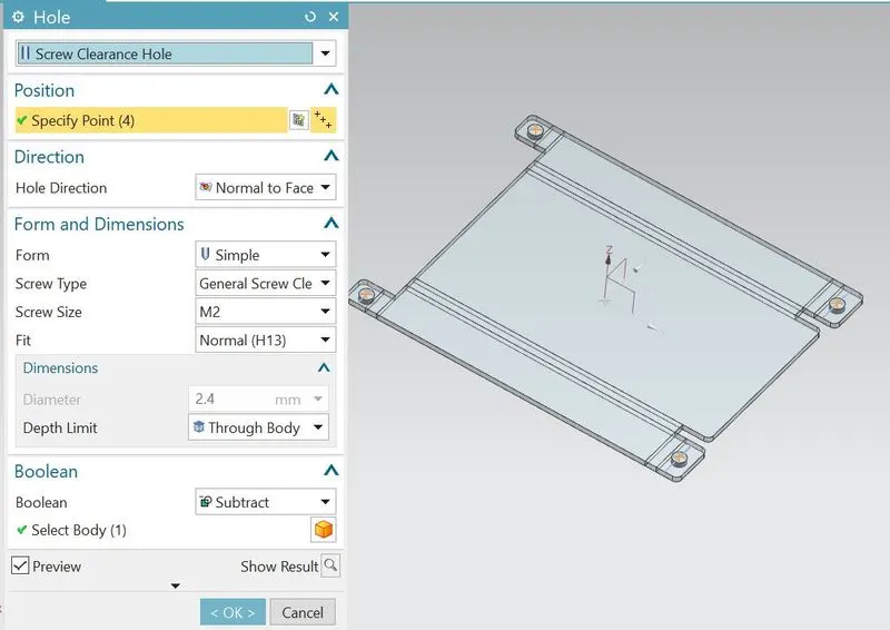
- Select the hole feature and select all 4 points as shown which is indicated in orange colour.
- Change screw type as general screw clearance and screw size as M2.
- Create the new sketch on surface of the plane and sketch the profile as shown below.
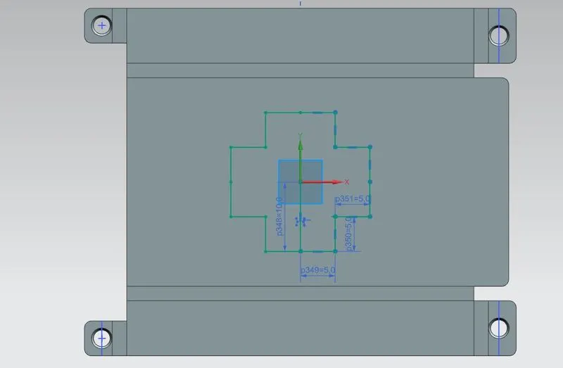
- Select the studio spline feature and select all the 16 points.
- Change the pole type as By poles.
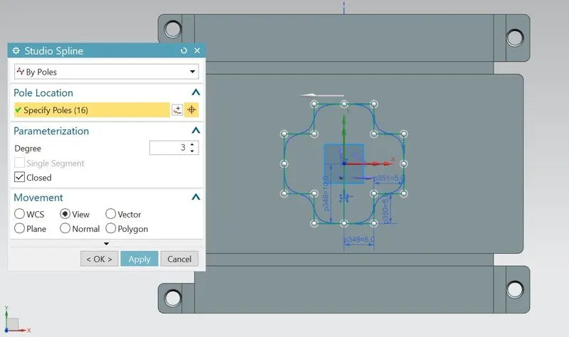
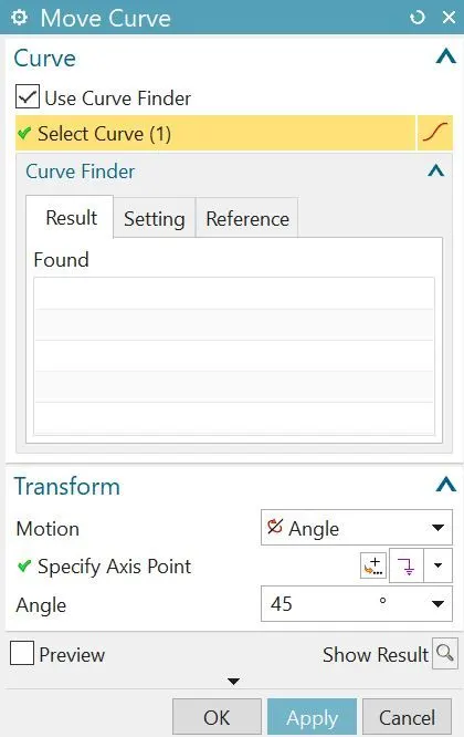
- Select the move curve feature and select the spline curve
- Select transform motion to angle and anlge as 45 degrees.
- Select the axis point as origin point.
- Click ok and trim the extra lines.
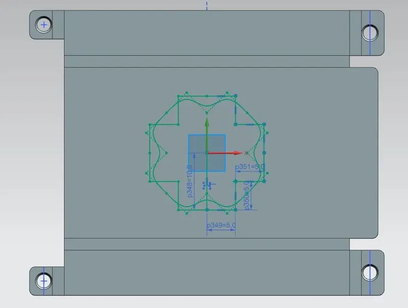
- Select the dimple feature and select the spline curve.
- Change the depth to 1mm and also rounding parameters to 1mm.
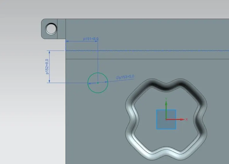
- Create the sketch on XY plane and draw the circle of 5mm diameter as per dimensions as shown below.
- Exit from the sketch.
- Select the bead feature and select the circle curve.
- Change the cross section type to circular and change die radius as 1mm.
- Click ok.
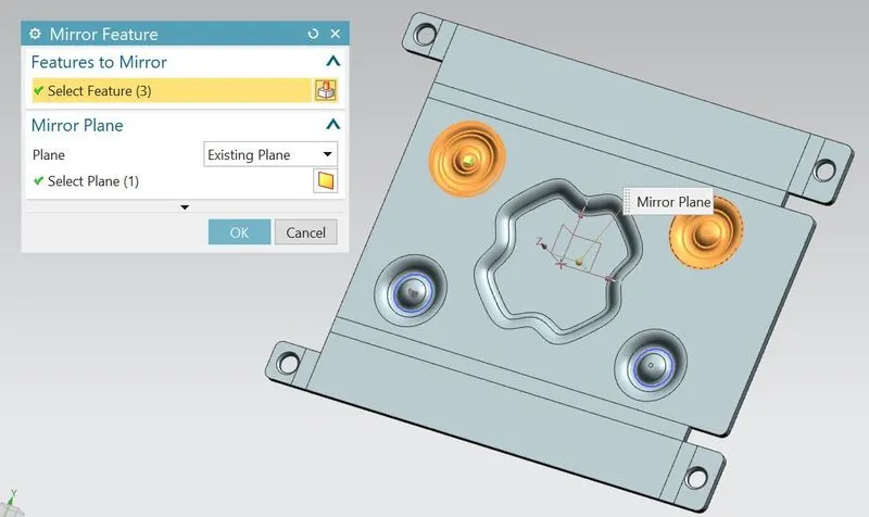
- Select the mirror feature.
- Select the bead sketch and bead as feature to mirror.
- Select YZ plane as mirror plane.
- Click ok.
- Select the mirror feature.
- Select the bead sketch,bead and mirror bead as feature to mirror.
- Select XZ plane as mirror plane.
- Click ok.
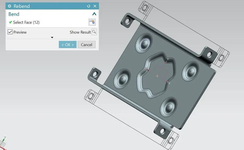
- Select the rebend feature and rebend the faces by selecting them in a reverse order from whch they are bend.
- Click ok.
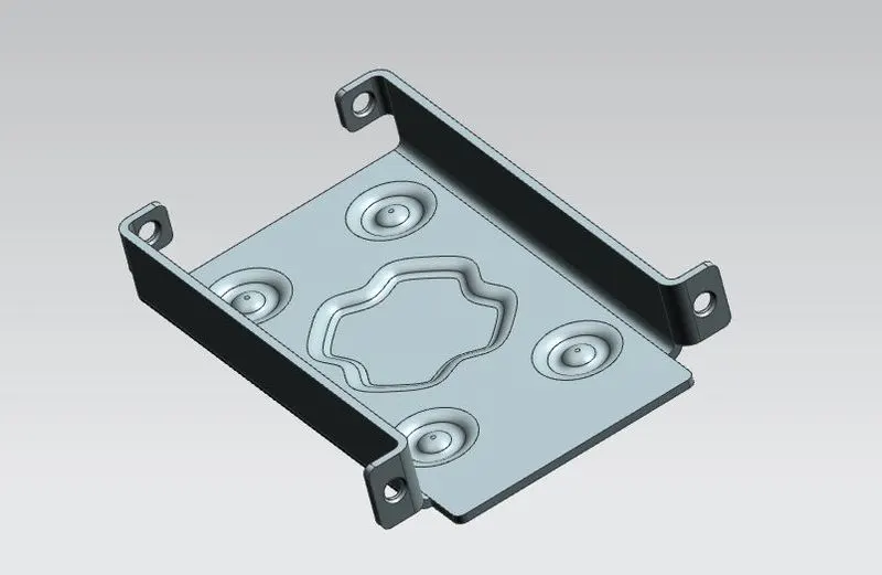
- Hide all the sketches inorder to clear view of the entire model as created.
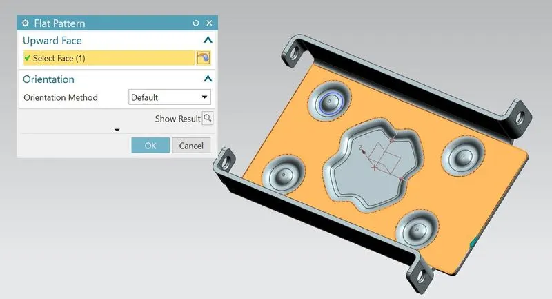
- Select the flat pattern feature and select the flat face of the sheet metal.
- After clicking ok,an dialogue is open and proceed by selecting ok.
- As the flat face of sheet metal is not visible normally.so double click on flat pattern feature in tree diagram will show the result as we created.
- Once the model completed and can proceed with Drafting.
- select the drafting ribbon from the application tab as shown below.
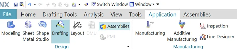
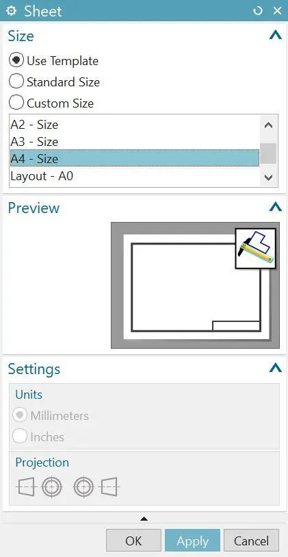
- Automatically it opens the sheet dialogue box and select the sheet size as A4.
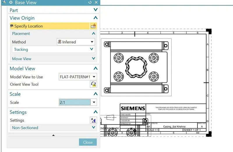
- Select the base view tab feature and dialogue box is opened.
- Change the model view to Flat pattern as we created and also the scale ratio to 2:1.
- As the draft will be too big.so use the orient view tool to rotate the draft as shown.
- A lot of information is developed related to draft and it is removed or keep as per the necessity.
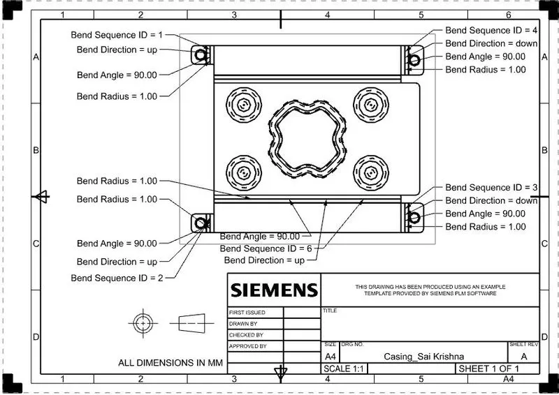
- Once the drafting is completed click on the save button to save the entire work.
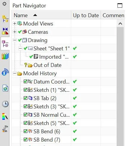
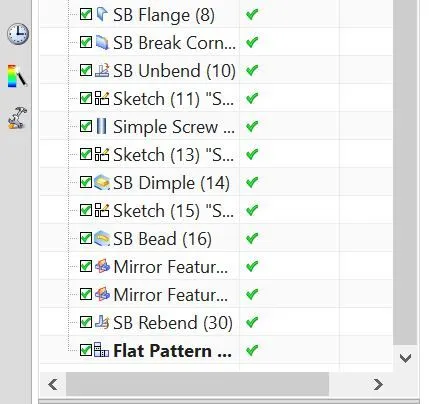
Tree diagram of part navigator:
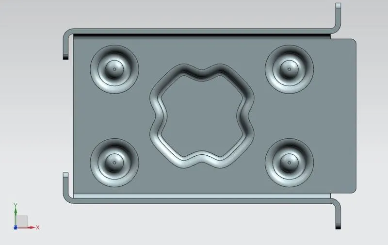
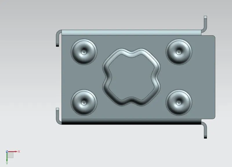
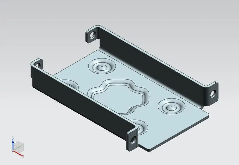
Different views of Sheet metal casing:
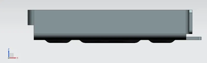
Front view
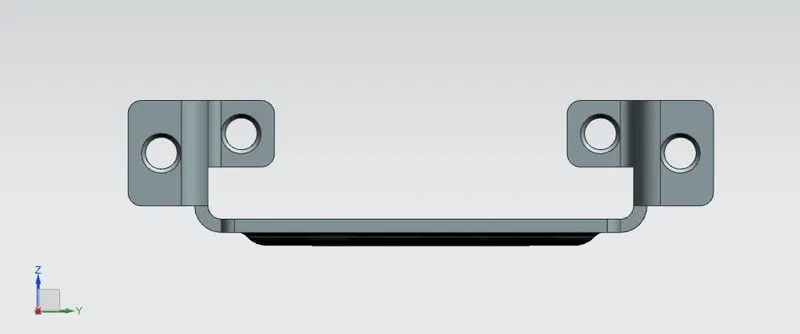
Right view
Top view
Bottom view
Isometric view
Drawing Sheet Image:
Conclusion:
Design of sheet metal casing can be completed by using NX-CAD software and learnt a lot of features specially used for designing sheet metal components.
THANK YOU