Calculation of Stiffness in Structural elements
AIM: Calculation of Stiffness in Structural elements
Question 1:
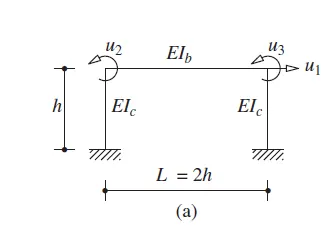
Compute lateral stiffness of the one story frame with an intermediate realistic stiffness of the beam. The system has 3 DOFs as shown. Assume L = 2h and Elb = Elc
SOLUTION:
The system has the three DOFs shown in Figure.
To obtain the first column of the 3×3 stiffness matrix, we impose unit displacement in DOF u1, with u2 = u3 = 0.
These are determined using the stiffness coefficients for a uniform flexural element.
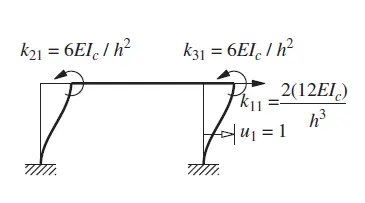
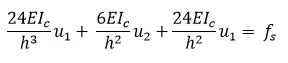
Motion equation in this case
The elements ki2 in the second column of the stiffness matrix are determined by imposing u2 = 1 with u1 = u3 = 0
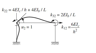
Motion equation in this case

Similarly, the elements ki3 in the third column of the stiffness matrix can be determined by imposing displacements u3 = 1 with u1 = u2 = 0.

Thus the 3×3 stiffness matrix of the structure is known and the equilibrium equations can be written. For a frame with Ib = Ic subjected to lateral force fS, they are
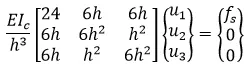
The joint rotations can be expressed in terms of lateral displacement as follows:
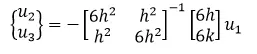
On solving we get
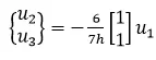
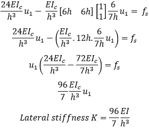
Substituting the above Eq into the first of three equations gives
Question 2:
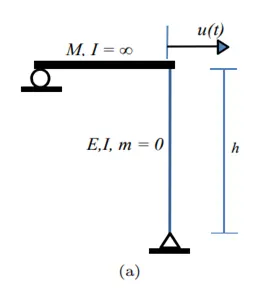
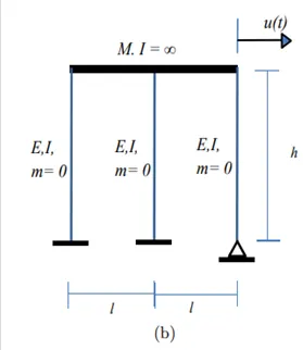
For the following structures:
- Determine the number of degrees-of-freedom for dynamic analysis
- Establish the equation of motion
- Calculate their natural frequencies
Solution
|
(a) No of Degree of freedom: Only 1 DOF |
(b) No of Degree of freedom: Only 1 DOF |
|
Equation of motion: The standard equation of motion is given by m +ku=0 Stiffness (k) of the frame is given by, By substituting the above value of stiffness in equation of motion we get the equation as follows:
|
Equation of motion: The standard equation of motion is given by m +ku=0 Stiffness of columns 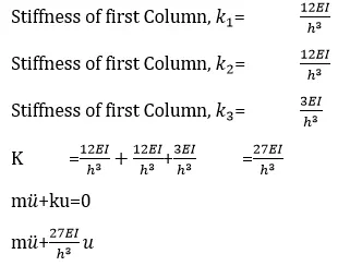 |
|
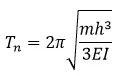
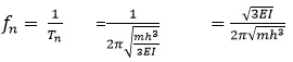
Natural frequency:
Stiffness (k) value is substituted in the equation
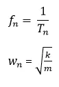
Rearranging the equation we get the equation as follows Now
On rearranging we get
We have
|
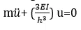
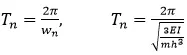
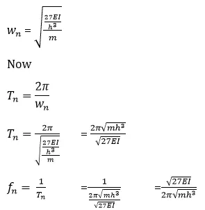
Natural frequency:
Substituting K value in the Eq
|



Question 3:
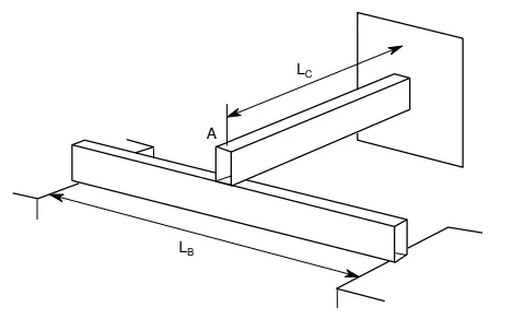
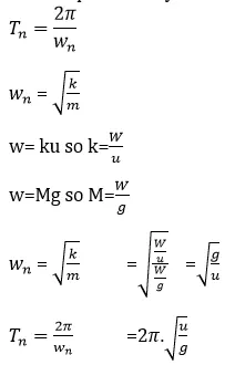
Consider the propped cantilever shown in the figure below. The beams are made from the same steel section and have lengths as shown on the diagram. Determine the natural period of this system if a large mass, M, is placed at the intersection of the beams at point A. The weight of the beams in comparison with the mass M is very small.
Natural period of system
Question 4
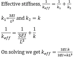
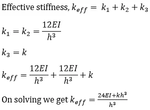
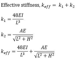
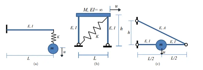
Determine an expression for the effective stiffness of the following systems:
|
(a)
|
(b)
|
(c)
|