To calculate dead and live load for industrial steel structures and to apply them using TSD
AIM: To calculate dead and live load for industrial steel structures and to apply them using TSD
Introduction:
Tekla Structural Designer is an integrated model-based 3D tool for analysis and design (of both concrete and steel members) in multi-material structures.
Features include interactive modeling, automated structural analysis and design, drawing, and report creation.
Multiple design codes are supported:
- ACI/AISC
- Eurocodes
- British Standards
- Indian Standards
- Australian Standards
We can use panel loads to apply loads to slab items, roof panels, and wall panels. Tekla Structural Designer contains several types of panel loads, including point loads, line loads, patch loads, polygonal loads, area loads, slab loads, and level loads. In order to apply the different panel loads to your model, see the following instructions.
We can use the different panel loads in the following ways:
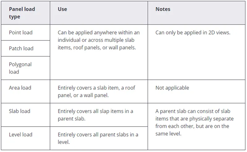
Create point loads
- Open a 2D view of the level within which you want to apply the load.
- In the Loading list, select an appropriate load case.
- On the Load tab, click Point Load.
- In the Properties window, adjust the load details according to your needs.
- In the model, click a reference node from which the load position can be offset. The load position can be the start or end point of any member at the level.
- Click the load position, or press F2 to type the exact position.
Create line loads
- Open a 2D view of the level within which you want to apply the load.
- In the Loading list, select an appropriate load case.
- On the Load, click Line Load.
- In the Properties window, adjust the load details according to your needs.
- In the model, click a reference node from which the load position can be offset.The load position can be the start or end point of any member at the level.
- Click the start point of the load, or press F2 to type the exact position. Note that the start point is an offset (X, Y) from the selected reference node.
- Click the end point of the load, or press F2 to type the exact position. Note that when you type the position using the keyboard, the end point is an offset (X, Y) from the load start position.
Create area loads
- Open a 2D view of the level within which you want to apply the load.
- In the Loadinglist, select an appropriate load case.
- On the Loadtab, click Area Load.
- In the Propertieswindow, adjust the load details according to your needs.
- Click the panel to which you want to apply the load.
Create slab loads
- In the Loading list, select an appropriate load case.
- On the Load tab, click Slab Load.
- In the Properties window, adjust the load details according to your needs.
- To apply the load to all the slab items within a parent slab, in the model, click any slab item within the parent slab.
Create level loads
- Click any slab panel in order to apply the load to all slabs within the level.
- In the Loading list, select an appropriate load case.
- On the Load tab, click Level Load.
- In the Properties window, adjust the load details according to your needs.
- To apply the load to all slabs within the level, in the model, click any slab item.
PART I
To Calculate dead load in design report based on IS code and apply dead load on the model
Finishes of 50mm
Slab as per design
Brick wall 150mm thickness
Roofing load based on purlin size
Ceiling loading 0f 0.3KN per sq m
PROCEDURE:
DEAD LOADS
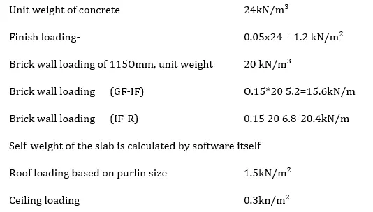
Initially based on IS 875 part I, all the dead loads in the steel structure were calculated as follows
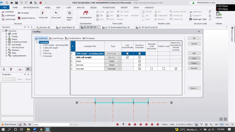
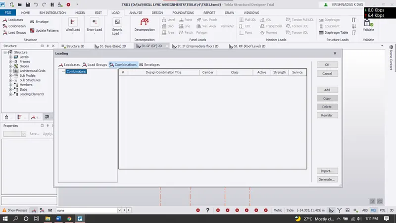
On the Load tab click on load cases option at the top left corner to open the loading dialogue box. It opens with these as the default loadings.
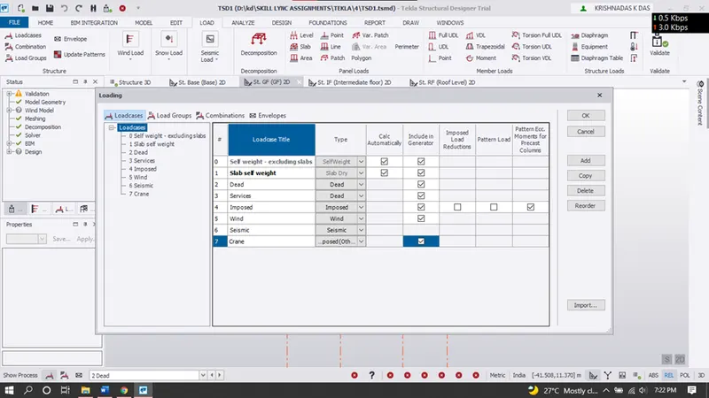
In order to add new loadings like imposed, wind, seismic and crane loads click on Add option in loading dialogue box and add them and select the type from the drop-down list.
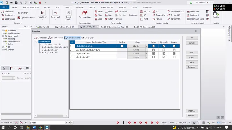
In the loading dialogue box click on combinations tab and to generate load combinations click on generate option below.
The load combinations will be generated as shown and we can further add and delete combinations as required.
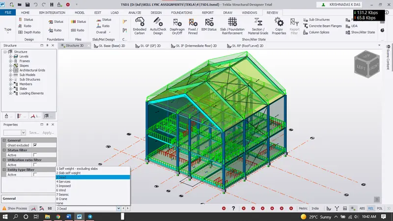
As we are going to apply the dead loads first select the dead loads option from the drop-down list as shown.
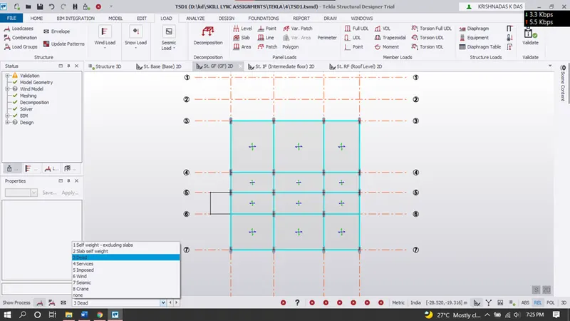
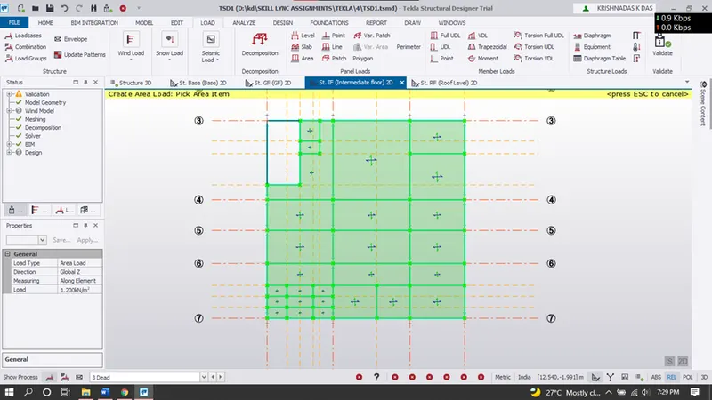
Open a 2D view (ground floor) of the level within which you want to apply the load.
In the Loading list, select an appropriate load case.
On the Load tab, click Area Load.
In the Properties window, adjust the load details according to your needs (1.2 ).
Click the panel to which you want to apply the load.
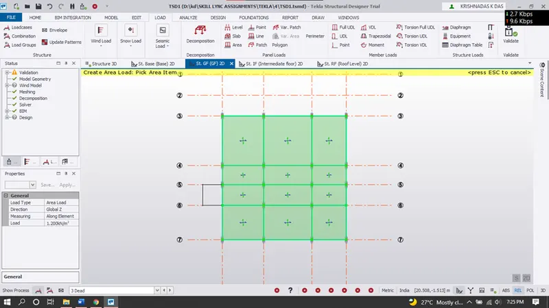
Intermediate floor/ First floor:
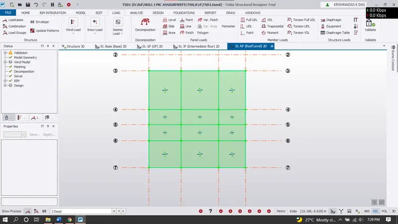
Roof level:
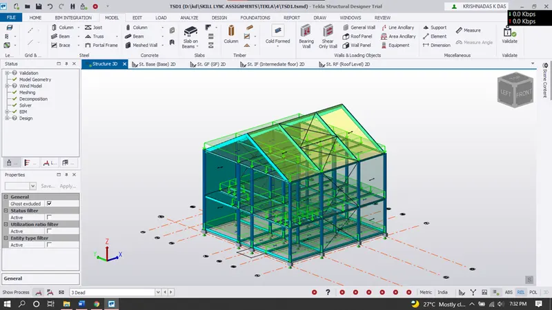
Validation was done to check for any error in modelling and 3D view of the same is a s shown below.
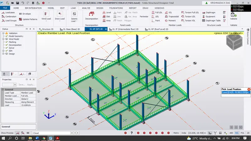
Open a 2D view (ground floor) of the level within which you want to apply the load.
In the Loading list, select an appropriate load case.
On the Load tab, click Full UDL.
In the Properties window, adjust the load details according to your needs (15.6 kN/m).
Click the beams to which we want to apply the load.
Now for the brick wall inside Line load was added as done below
Open a 2D view (ground floor) of the level within which you want to apply the load.
In the Loading list, select an appropriate load case.
On the Load tab, click Line load otpion.
In the Properties window, adjust the load details according to your needs (15.6 kN/m).
Click the brick wall inside the structure to which we want to apply the load.

3D view of the Ground floor in which UDL and line load is applied is a shown below
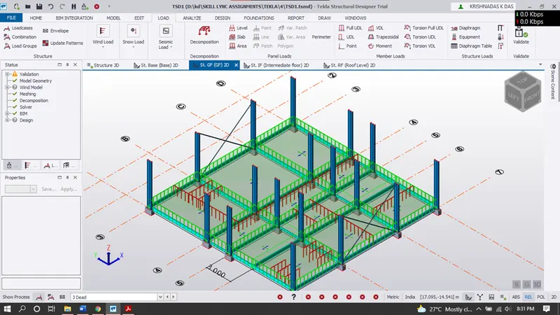
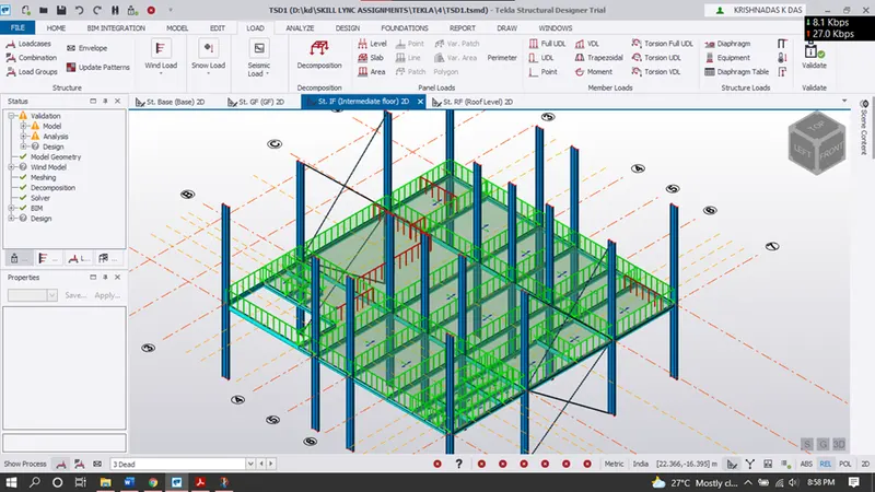
In the similar manner, UDL and line loads are applied in the intermediate/ first floor as shown. The only difference in loading and is 20.4
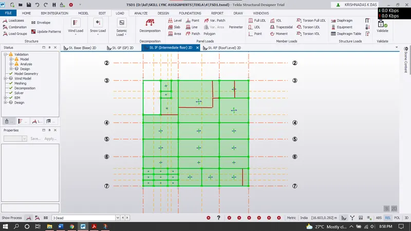
3D view of the intermediate/ first floor in which UDL and line load is applied is a shown below
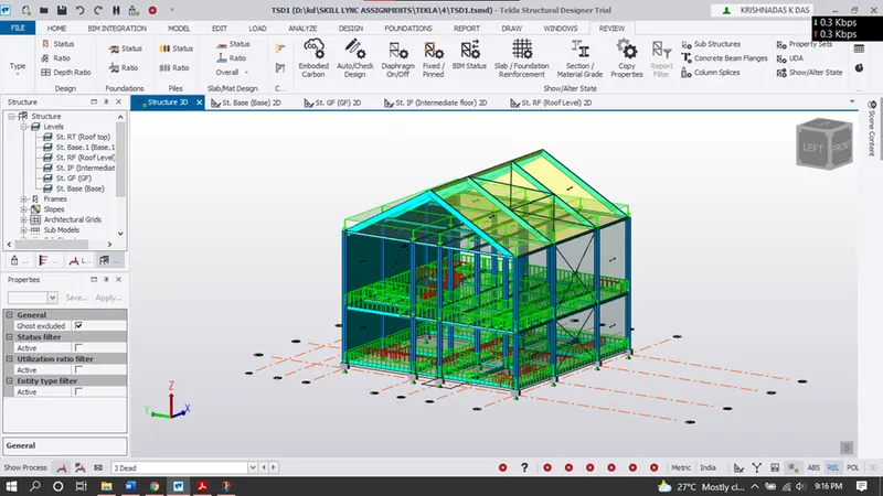
Next the roof load was applied and is as shown below. For that open the 3D structural view.
On the Load tab, click Area Load.
In the Properties window, adjust the load details according to your needs (1.5 kN/m^2).
Click the roof panel to which you want to apply the load.
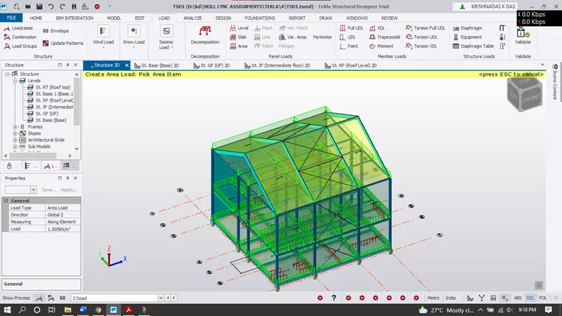
The roof loads are now applied and the model was checked for any errors.

PART II
To Calculate live load in design report based on IS code and apply live load on the model
Assume the loading based on IS 875
Roof loading
Consider equipment loading as 5KN per sq m
PROCEDURE:
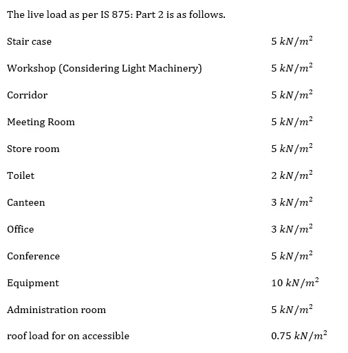
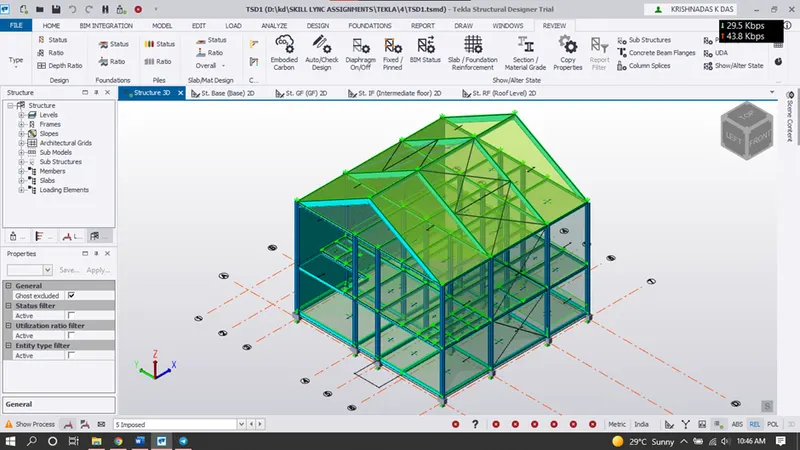
In the drop-down list below select imposed loads to apply the loads.
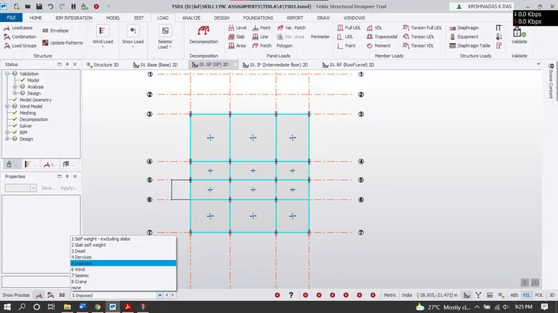
Open a 2D view of the level within which you want to apply the load.
In the Loading list, select an appropriate load case.
On the Load tab, click Area Load.
In the Properties window, adjust the load details according to your needs.
Click the panel to which you want to apply the load.
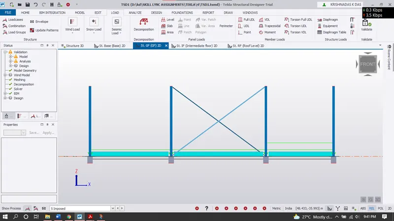
The loads were applied on each room based on what function it served. All the live loads was applied to all the rooms in ground floor.
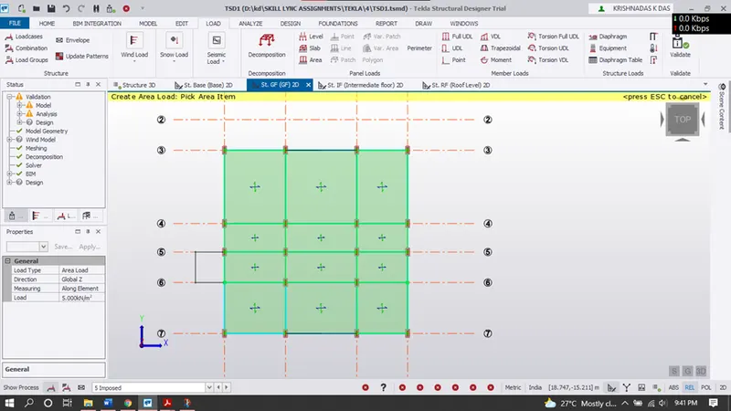
The front view of the same shows the height difference in line (green horizontal lines) , that implies if the load applied is high it will be at the top.
3D view of the same after validation is as shown below
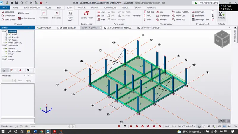
In the similar manner live loads, depending upon the function of each room the loads were applied in the intermediate/first floor.
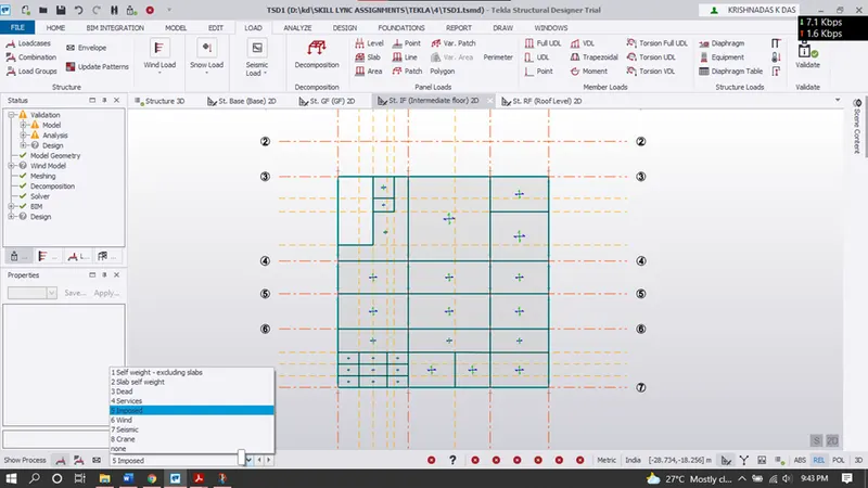
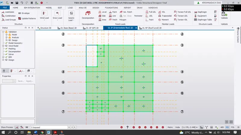
In the similar manner live loads, the loads were applied in the roof level.
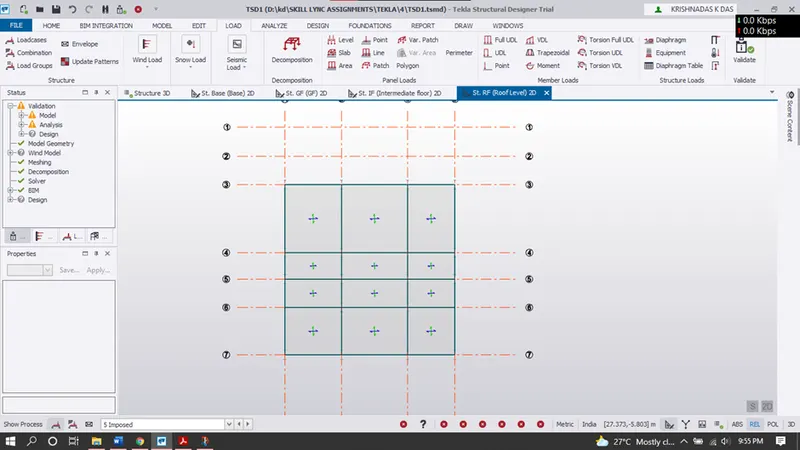
As the roof level doesn’t carry much load only .75kN/m^2 is applied for all rooms.
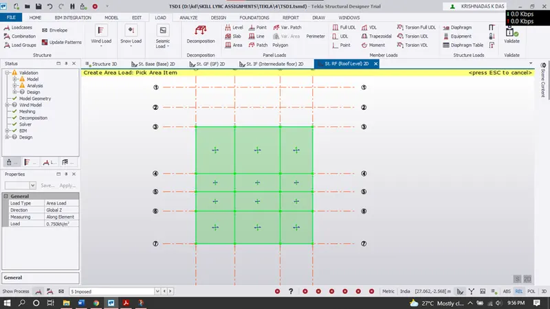
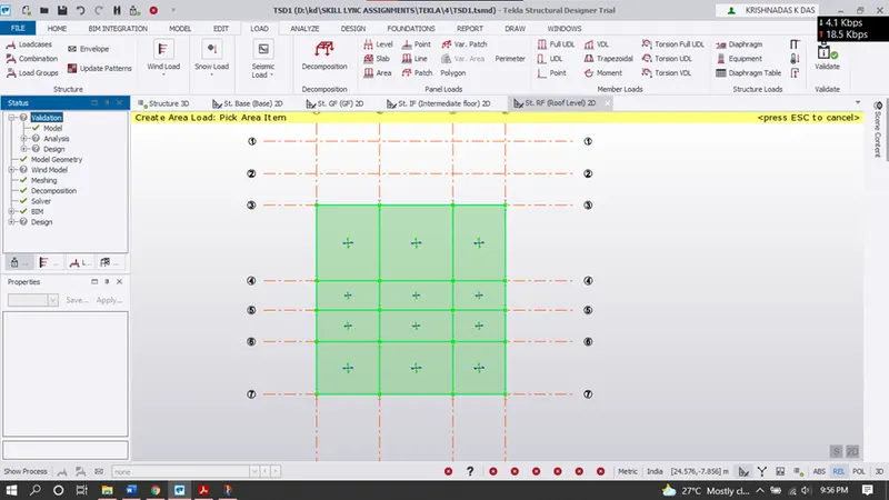
The model was then validated to check for any errors in modelling.
The 3D view of the same is as follows.
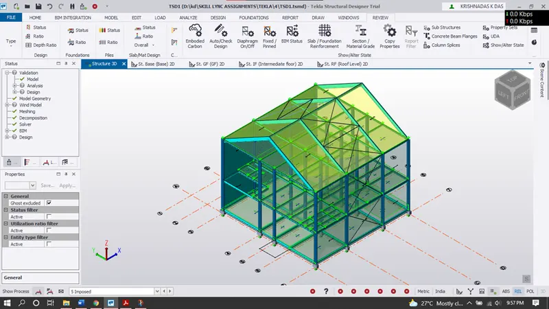
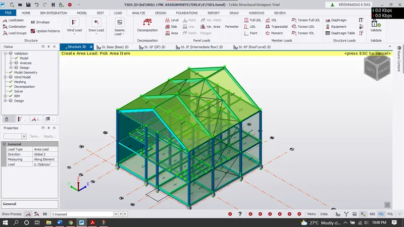
In the similar manner live loads of the roof was applied. As the slope of roof is greater than 10 degree a load of .750kN/m^2 was applied.
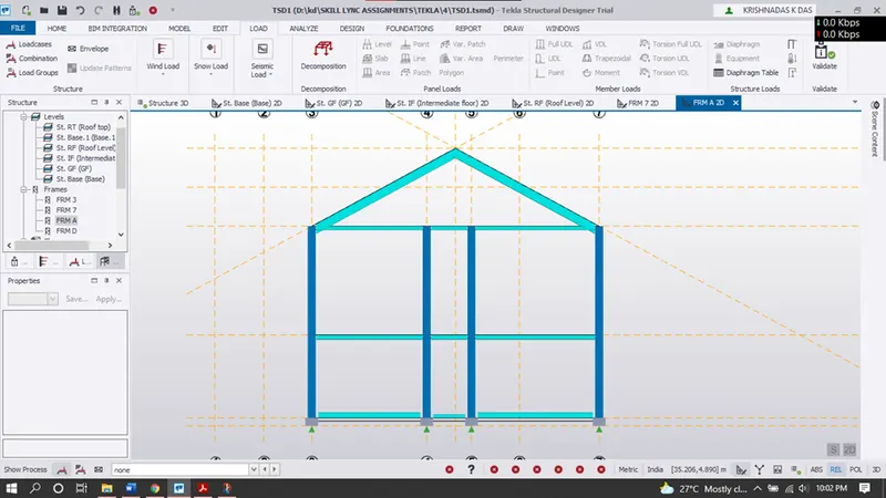
The 3D view of the same is as shown below.
RESULTS:
- The dead loads including finish loads and brick wall loads was calculated and applied on the structure.
2. Live loads were taken from IS 875 part II and was applied on the structure
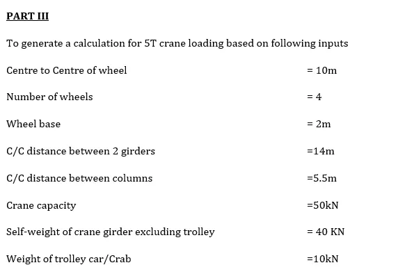
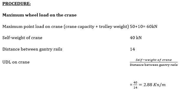
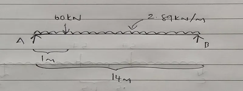
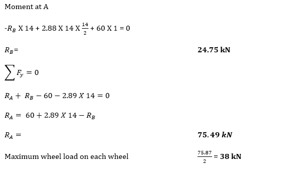
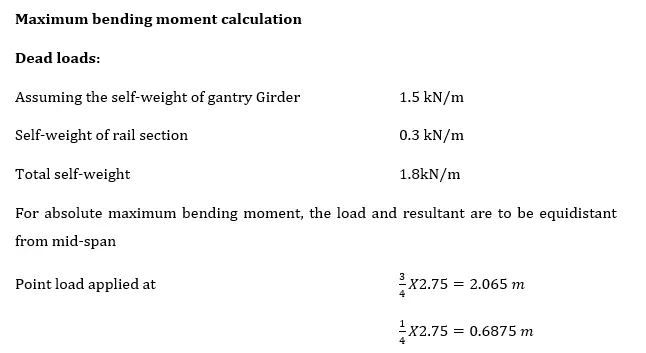
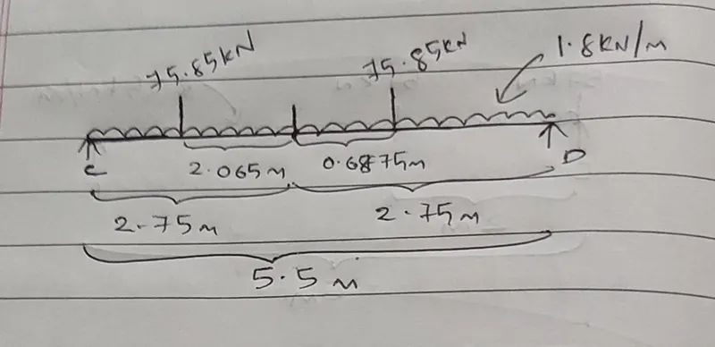
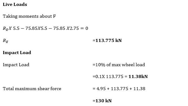
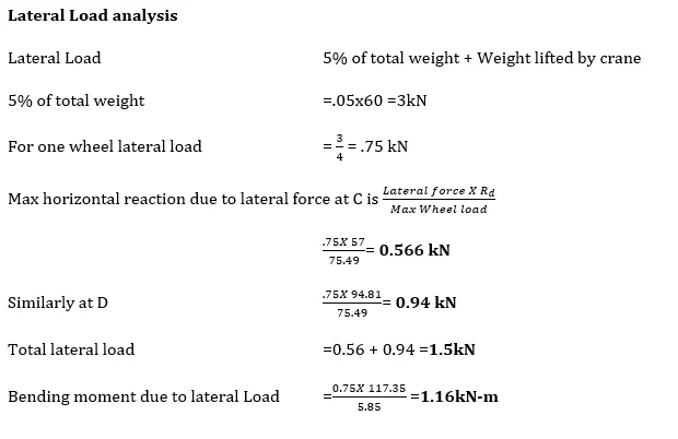
3. 5T crane loadings was manually calculated