Sunseeker Predator Yacht
MODELLING OF SUNSEEKER PREDATOR YACHT USING SOLIDWORKS
OBJECTIVE: To design various parts of a Sunseeker yacht and assemble them using Solidworks software.
INTRODUCTION:
A yacht is a vessel used for both leisure and competition. The term is derived from the Dutch word jaght, which means "hunter" and refers to a former type of quick, light sailing vessel. The term "yacht" quickly evolved to denote a vessel in which important people were carried, not just any old boat, after the English King Charles the Second was transported by it from the Netherlands to England in 1660. Yachts are primarily used for recreation today. Here, I used Solidworks to model a SUNSEEKER PREDATOR boat. Here is a quick report on the project.
DESIGN METHODOLOGY:
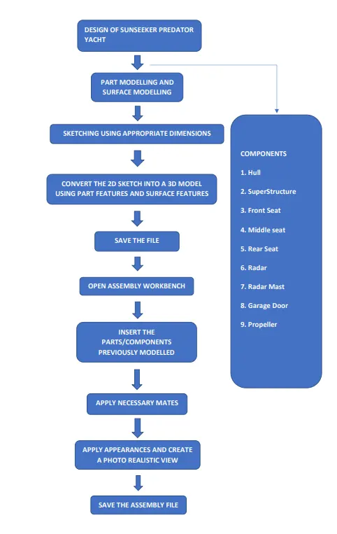
To start, we will design each component using appropriate measurements, which will enable us to produce a sketch that is perfectly defined.
- Assemble the parts with the right mates and relations to create the finished yacht model.
- Decals applied to the model and scene setup for realistic produced photos.
- Finally, use SolidWorks photoview360 and SolidWorks visualize to render the model with different scenario setups and appearances to produce photorealistic photos.
LIST OF COMPONENTS IN YACHT:
- Front Seat
- Garage Door
- Hull
- Middle Seat
- Propeller
- Radar
- Radar Mast
- Rear Seat
- Superstructure
BLUE PRINT:
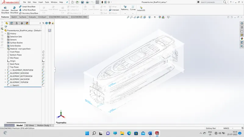
To model the boat, the goal is to create a Blueprint arrangement.
We need side view sketches, bottom sketches, back sketches, front sketches, and top sketches to create the blueprint layout. Each image was placed on its plane and given the necessary angles and locations. The appropriate scaling was carried out. Other photographs were also processed in the same way.
Below is the screenshot of the blueprint layout.
1. FRONT, MIDDLE AND BACK SEATS:
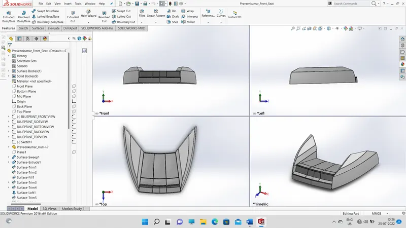
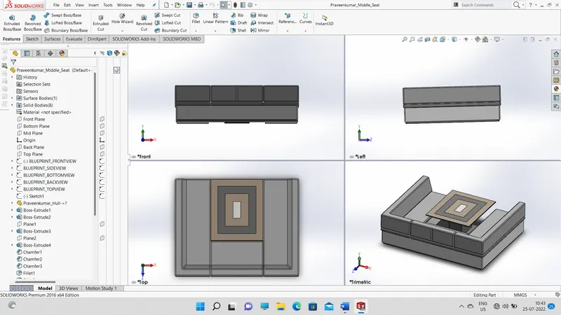
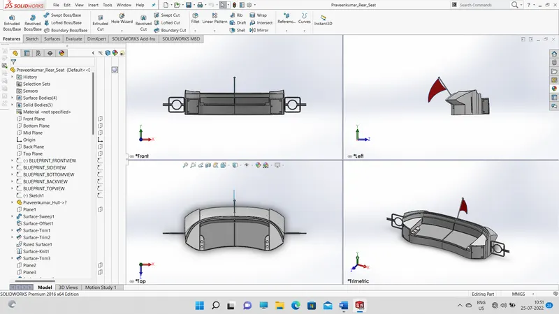
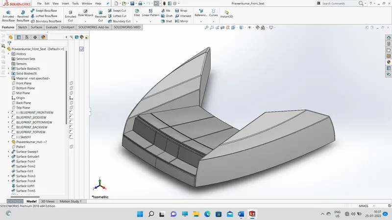
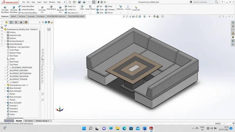
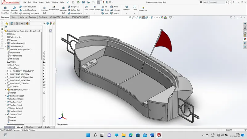
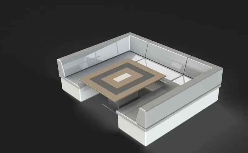
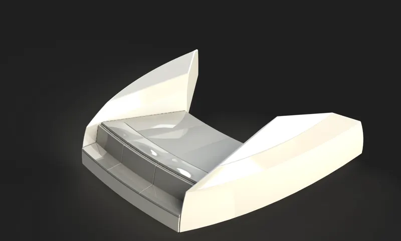
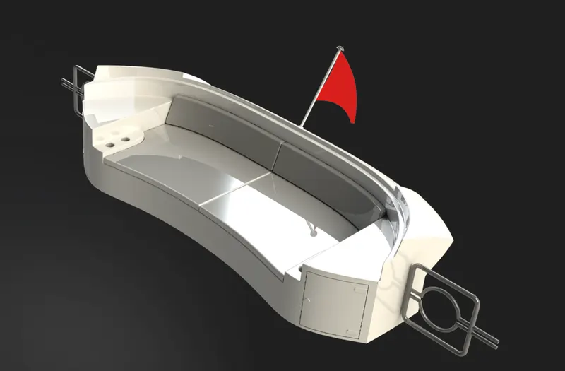
Here, I've modeled the yacht's front seat, middle seat, and back seat. For the front, middle, and rear seats, I used the blueprint setup file we made previously, as well as the upper deck surface. The majority of the time when making the front and back seats, surface tools were used. The seats are symmetric about the mid-plane, therefore half of the portion will be made up of surface modeling and other features, while the other half will be mirrored. We'll use a knit surface to transform the model into solid bodies. The boss feature is used to make pillows that are offset and spin. The pillows are given a curving look using the Dome function. Utilizing the lofted surface and rotating boss features, the flag on the backseat is produced. Fillets are provided at all relevant edges.
2. GARAGE DOOR:
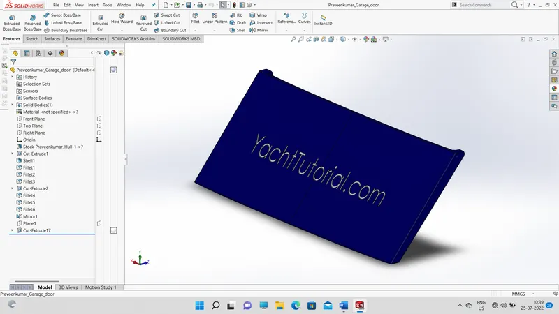
Here I have modeled the Garage door which will be assembled for the yacht later. Utilizing a split feature, this portion of the hull is utilized to produce a garage door. Using an extrude cut feature, the garage door's superfluous portion is first eliminated, and a shell feature is used to make the door hollow. Since the door is symmetrical about the midplane, we will first construct half of the door before mirroring the other half. At all necessary edges, there are fillets. The extrude cut feature is used to create a text on a different plane, which is then projected onto the garage door.
3. HULL:
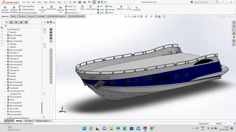
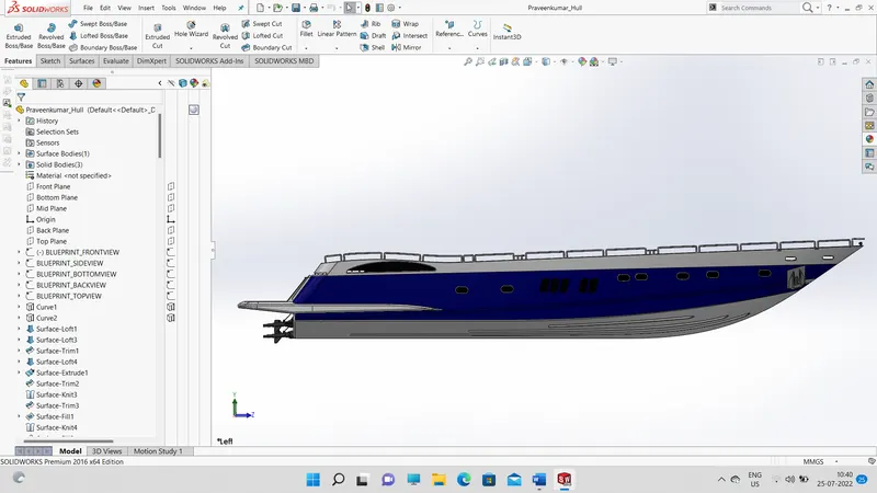
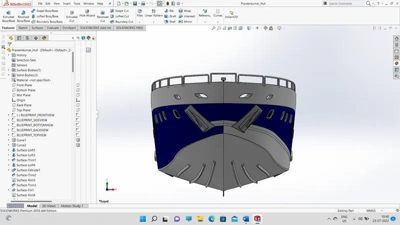
The yacht's watertight enclosure is called the hull. The yacht's occupants and the yacht's machinery are housed in these chambers in the hull. It is the yacht's most noteworthy structural component. Here, I incorporated all the necessary dimensions as well as the yacht's blueprints. Creating the hull primarily involved surface modeling. Lofted surface, extruded boss, sweep boss, extruded surface, Surface offset, revolved boss, and surface knit are features utilized when modeling the yacht's hull. First, blueprints for all the views are placed in the environment. The surface bodies of the hull are created using these blueprints as a guide. Make the surface bodies into solid objects by applying the knit-surface feature. When using the offset surface feature, a surface is produced by setting the offset distance to 0. This area of the hull's deck appears to be concealed. For seat modeling, this surface is utilized as a reference. The hull's deck, stairways, and garage space floor all have decals.
4 . PROPELLER:
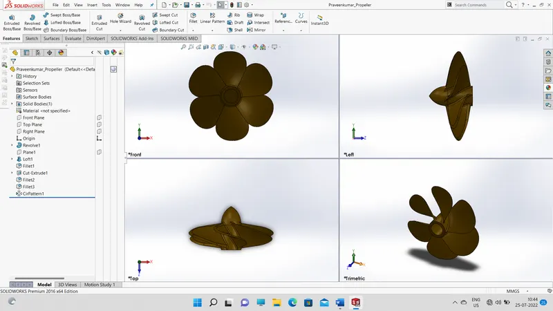
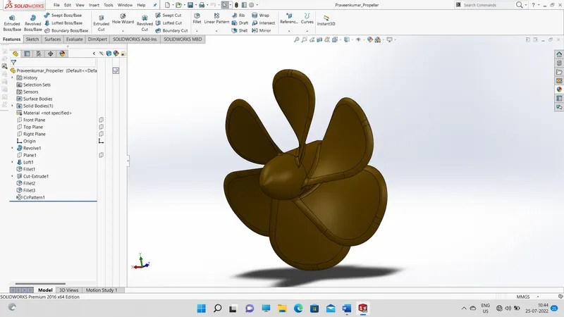
Three identical propellers, each with six blades, are on the Predator yacht. The yacht's weight is typically taken into consideration while determining the number of blades. More surface area is needed for the blades to propel the boat through the water with the least amount of slip and cavitation the heavier the vessel gets. I first used the line tool and spline tool to draw up the propeller hub with the necessary proportions and relationships. I then turned it about an axis. The top of the blade, which is away from the hub, and the bottom, which is fixed to the surface of the hub, were then sketched. With the help of the previous two sketches, a solid loft was built. The blade was then covered with the appropriate fillets. The remaining 5 blades were then modeled around the hub using a circular pattern. To fix the propeller to the shaft, a cut extrusion was made on the hub. Finally, the propeller received the proper finishing touches.
5 . RADAR:
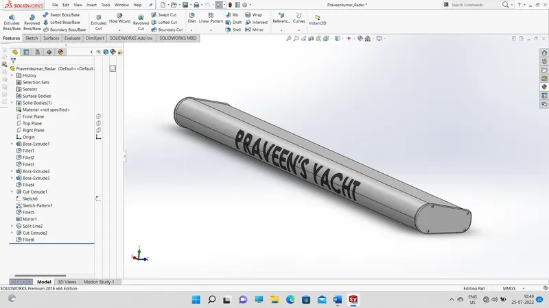
Marine radars are the best collision avoidance system ever developed for recreational boaters. Radar systems let you “see” through the darkness, fog, and stormy weather conditions. To model the Radar, I first sketched the cross-section and extruded it. Apply the necessary fillets. Finally, I altered the font style and color of the text that contained my name and added it to the surface of Radar. On the radar, the proper appearance was applied.
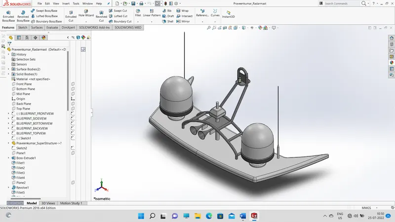
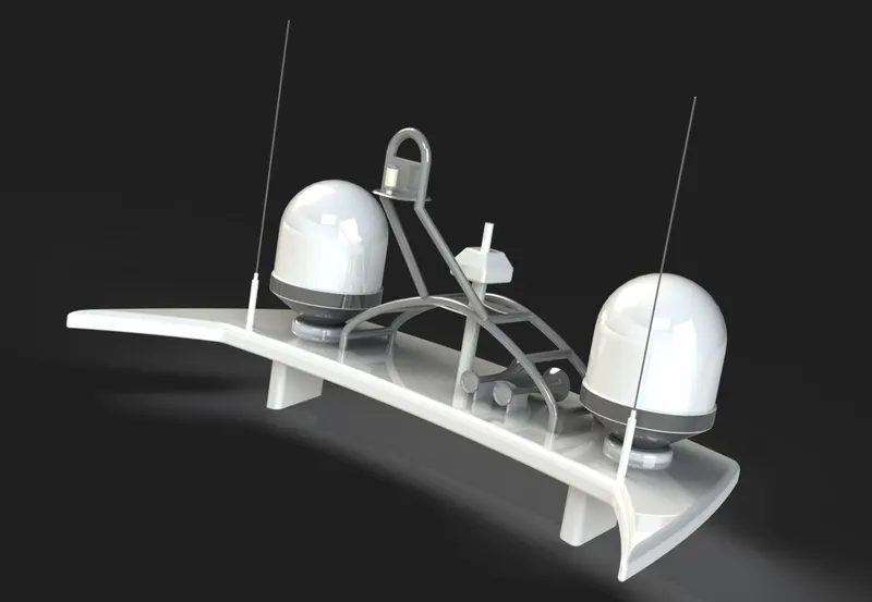
6. RADARMAST:
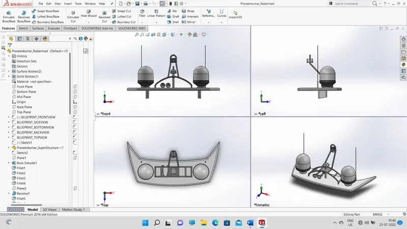
First import the reference surface from the superstructure. Different features are used for creating the radar mast. Projection curves are used for creating the pipes. Necessary fillets have been provided at the edges.
7 . SUPERSTRUCTURE:
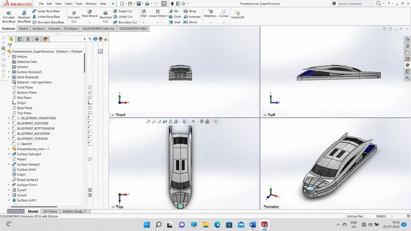
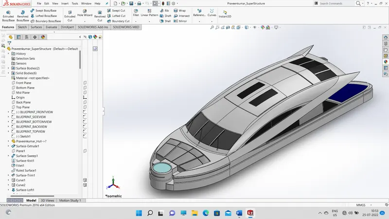
Here, I used Solidworks to model the yacht's superstructure. Any extended building or platform construction that stands out from the rest of the structure is known as a superstructure. So, to add a structure to an existing structure is to the superstructure. The superstructure of our yacht protrudes from the deck. Superstructure modeling mostly utilized surface modeling methods. I used the yacht's blueprints and all the available dimensions in this case as well. The most common surface modeling tools employed were lofted surface, knit surface, revolved surface, extended surface, trim surface, and ruled surface. Additional features included "extruded boss/base," "extruded cut," "rotated boss/base," and others.
ASSEMBLY:
1. Smart Mate - A Smart mate is an assembly mating relation that is created automatically.
Mate - A mate is a geometric relationship, such as coincident, perpendicular; tangent, and
so on, between parts in an assembly.
2. Mate group - A mate group is a collection of mates that are solved together. The order in
which the mates appear within the mating group does not matter.
3. Sub-Assembly - A subassembly is an assembly document that is part of a larger
assembly. For example, the steering mechanism of a car is a subassembly of the car.
4. Insert Components - We can insert multiple instances of the group of components without
closing the Property Manager.
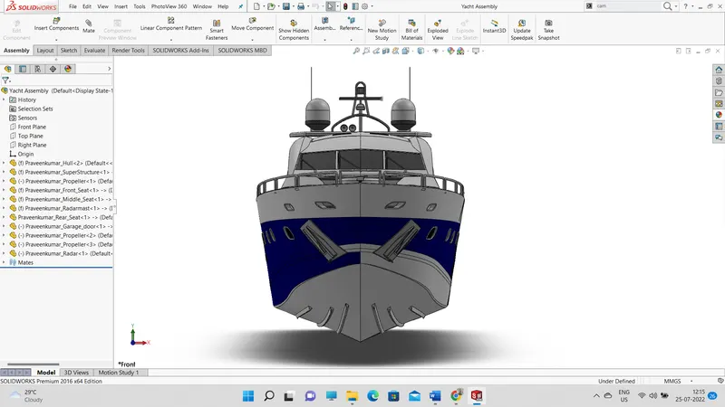
Front View:
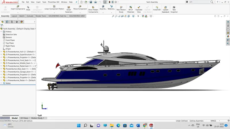
Side View:
Camera View:
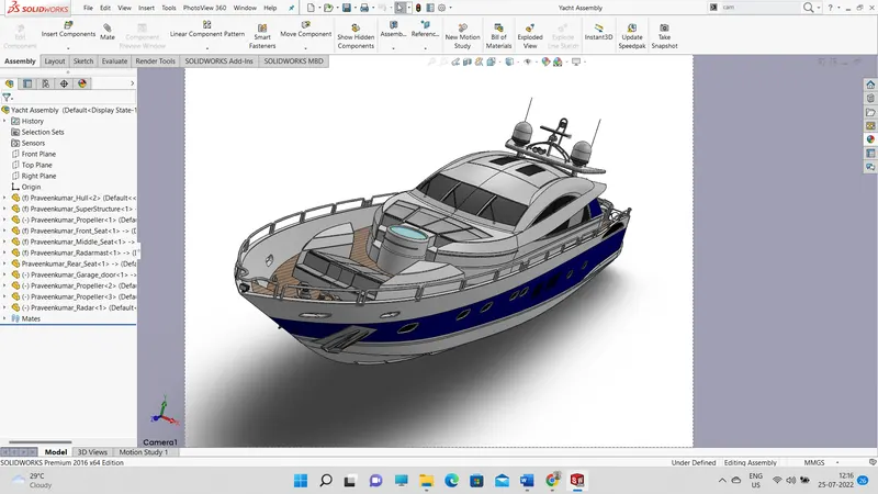
Isometric View:
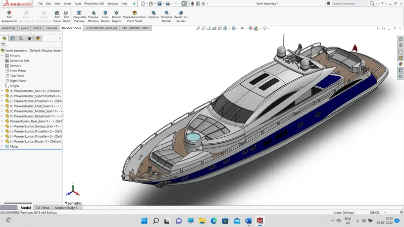
Rendered Images:
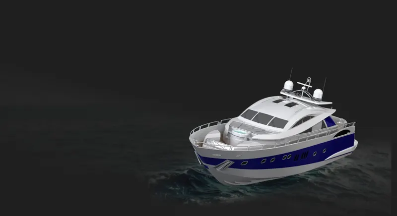
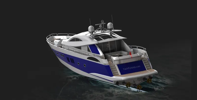
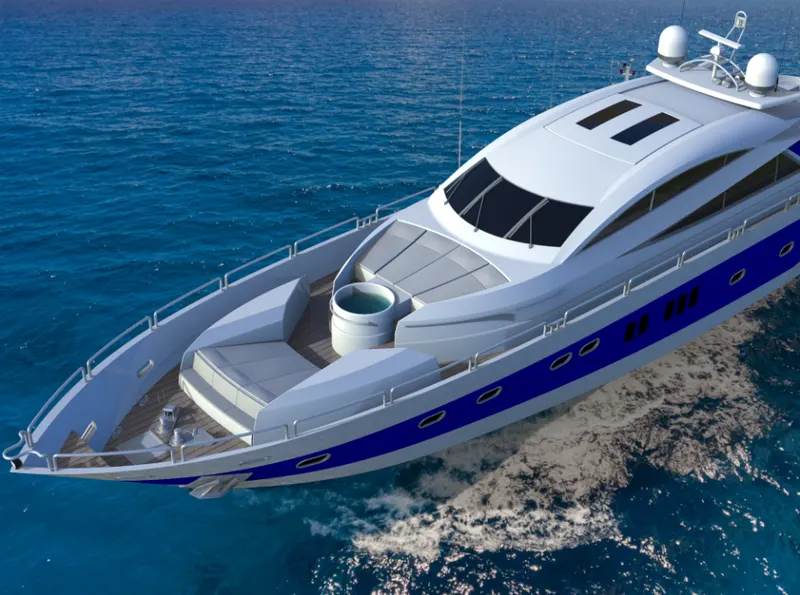
CONCLUSION:
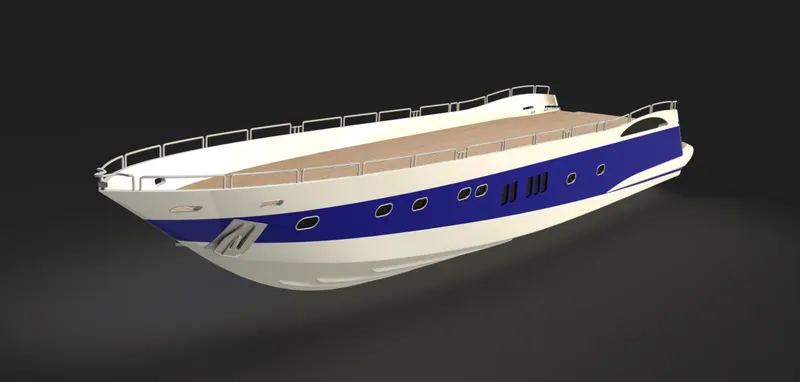
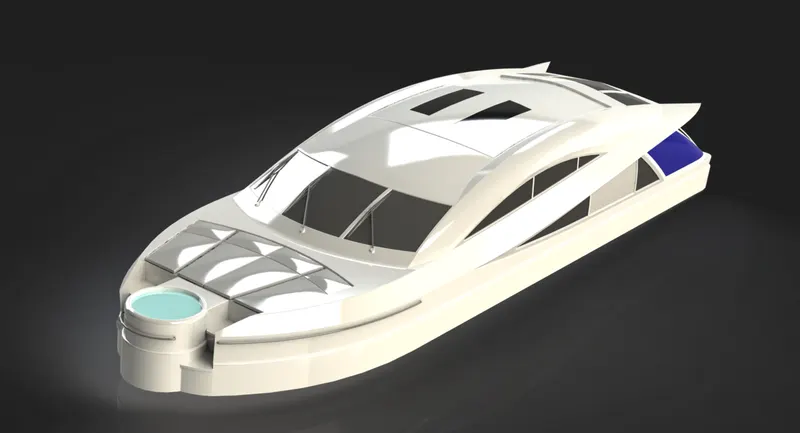
The SUNSEEKER PREDATOR YACHT is successfully modeled using solid works and is then rendered using photo view 360.
Through this project, I learned surface workbench and part workbench.