Advanced Sheet Metal Design Using NX Cad Challenge_7_ Metal bracket-II
DEESIGN OF SHEET METAL BRACKET -2 USING A NX CAD SOFWARE.
OBJECTIVE:-
to create a sheet metal part 2 using a vaius operations performed in nx sheet metal software using a 2d drawing
INTRODUCTION:-
UG NX software is a flexible and powerfull integrated solution that helps you deliver better product faster and more efficiently.
DESIGN METHODOLOGY:-
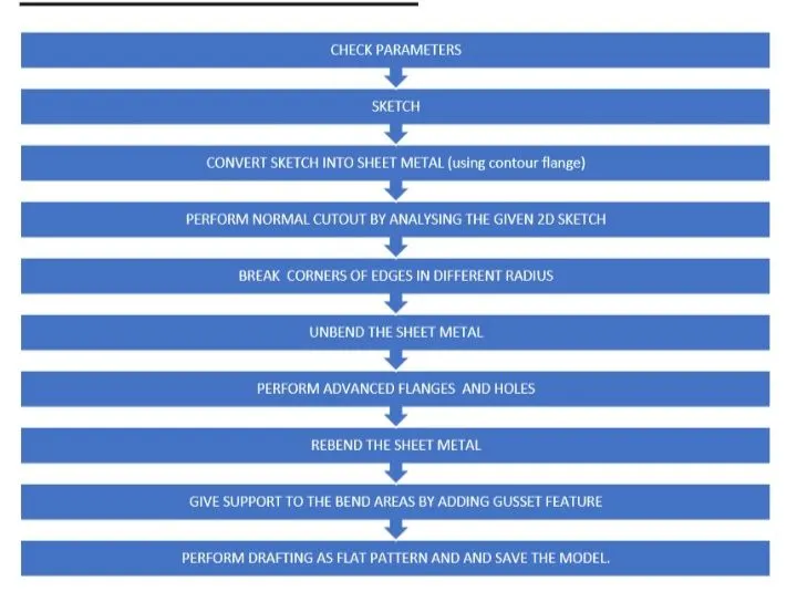
TOOLS USED WHILE DESIGNING THIS PART:-
1-sheet meteal operation
this operation is used for creating a sheet metal model.
2-SKETCH
This is a basic and first step or creating any model .in this we can edit the diamentions of the sketch
we neeed to select the plane first according to espective view.
3-FLANGE:-
used to add a material at edge and give the length and angle as required.
4-NORMAL CUTOUT:-
used to make a cutout af any shape on sheet metal.
5-BREAK CORNER:-
used to make a sharp corner
6-UNBEND:-
used to unbbend the all bend aeras
7-HOLE:-
this used to make a hole as reqired diamention.at required place
8-REBEND:-
in this we can rebend all flanges and bend areas to the original shape of the sheet metal.
10-GUSSET:-
it is the feature addwd to give the stiffnes to the bend areas hence increasing the strength to the part.
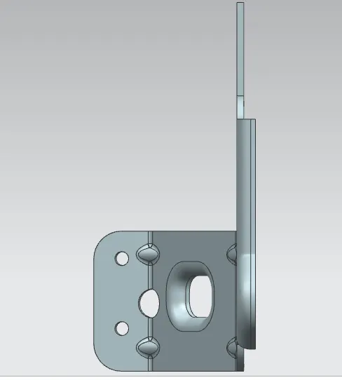
Varius views of the sheet metal bracket -2:-
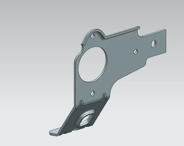
isometric-
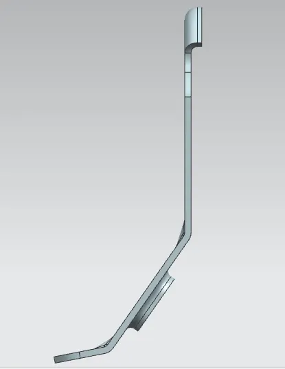
front-
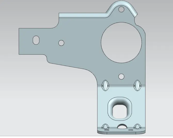
left-
top:-
CONCLUSION:-
design the sheet metal part 2 is competed using the varius tools and command avilable in NX software .