Advanced Sheet Metal Design Using NX Cad Challenge_2_Box Assembly
DESIGN OF BOX ASSEBLY:-
OBJECTIVE:-
the main purpose of this project is to create the sheet metal Box assembly with some apperances by using the sheet metal feature in NX .
introduction:-
sheet metal is the is formed by an industrial process into the thinand flat pieces.
sheet metal is the fundamental formes used in mmetalworking.and it can be cut and bend in the variety of shapes.
design methodologe:-
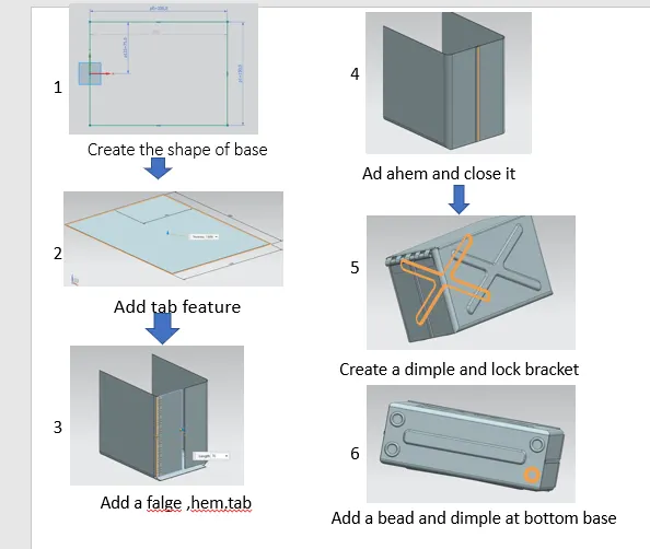 7
7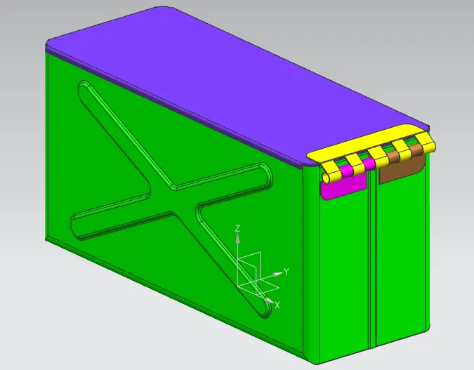 and add the appearacnce to box.
description:-
tool used for creating the box aseembly are as follow:-
TAB:-
is only used in designingg the metal parts.it is base where the base is created.
FLANGE:-
this command used to add a flate flange to a bend portion of the casing.
it cconsist of toe regin
1-bend region
2-Web region
CLOSED CORNER:-
it used to modified to tow flages in one operation and to close the corner where tow flange are meet.
HEM FLANGE:-
it is to modified an edge of a sheet metal part by folding into itselffor the purpose of safe handling.
MIRRORE BODY:-
the command used to mirrore the body created with respect to the plane section.
UNITE:-
use to combine the tow bodies into the single body.
DIMPLE:-
the dimple faeture cane be place at any flate face.dimple are design to redused the weight in sheet metal fabrications,whie adding strength and regidity.
BEAD:-
ead is drawn out imression.which is impress to incresed stiffnes in metal sheets or plates .it is also important that how the bead run over the workpiece.
BREAK CORNER:-
USED TO ROUND OR CHAMPER THE CORNER
NORMAL CUToUT:-
use to acut material by projecting a sketch line on to the model and cutting perpendicuar to the faces itersected by the projectin.
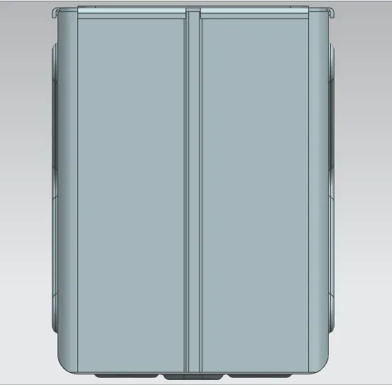
DIFFRENT VIEWS OF THE MODEL:-
isomertic-
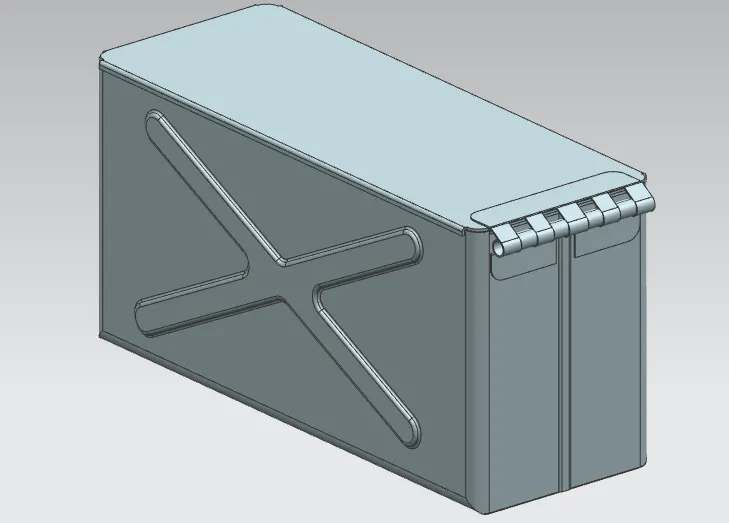
front-
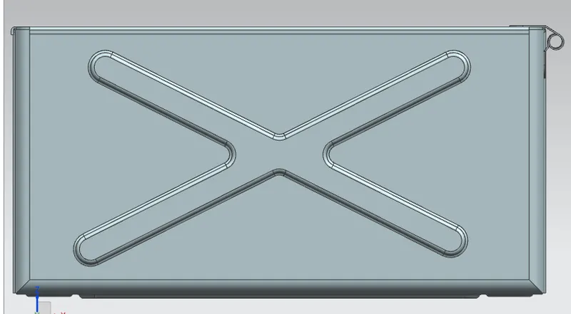
top-
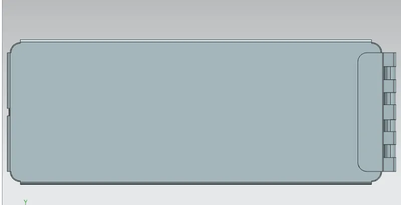
left-
CONCLUSION:-
the shhet metal box assembly get completed by using the required features at the required diamentions to the sheet metals.