Photo Realistic Rendering
DESIGN AND RENDERING OF AMERICAN CHOPPER
- OBJECTIVE-
- To learn the diffrent technices of solid work as well as surface modeling using solid work by desingnig American chopper
- to creat diffrent part of a ameriacn chopper in solidwork using varius types of sketches and fetures tool
- to assemble the different modelled part to create the chopper
INTRODUCTION-Solidwork is published by Dessault System.solidwork is a solid modeling computer-aided design and computer-aided engineering computer program.the chopper were was modelled using part modelling.Once the after all part were modelled separately they were assembled to crete the chopper.
FLOW CHART OF CHOPPER PARTS
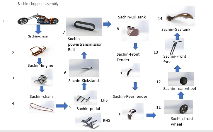
It conist of following Parts
- chassi
- engine
- chain
- Front fender
- Front fork
- Fuel tank
- Front wheel
- Kick stand
- Oil tank
- pedal
- pedal LHS
- Rear wheel
- Rear fender
- Transmission belt
DESIGN METHODOLOGY OF EACTH PART-
1.Transmission belt-
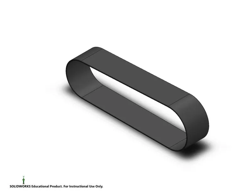
A belt is aloop of flexible material ,Belt used a sourse of rotational motion ,to transmit power between the tow pulleys and the shafts,belt also used to link tow or more shafts mechanically.
- commands used to design:-
- 2D skecth
- smart diamensions
- Extrude boss/base
- mirror feature
- curved dreaven pattern
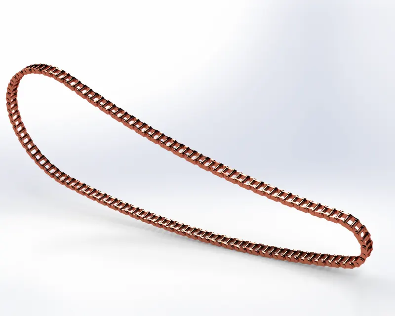
CHAIN:-
chain is most important part of motercycle which is use to transmit thr motore power to back wheel.lubricant use to increase the efficiency of chain
commands used to design:-
- 2D sketch
- smart diamensions
- Extrude boss/base
- fillet
- apperance
- mirror
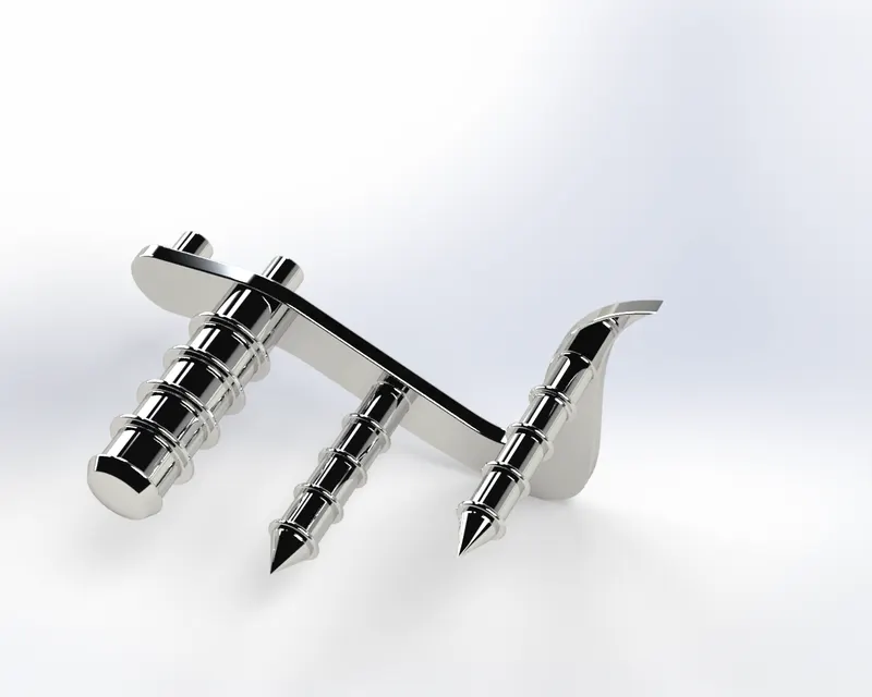
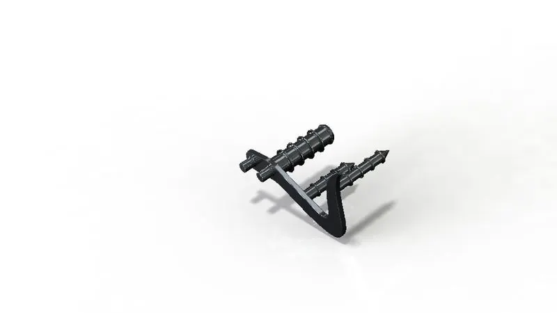
PEDAL:-
it is a foot leaver
command used to design:-
- 2D sketch
- Extrude Boss/Base
- fillet
- champer
- smart diamensions
- Revolve Boss /base
- dome
- linear pattern
- Appearance
Pedal LHS:-It is the mirrored part of the pedal across the mid plane
Commands use to design:-
- Mirror feature
oil tank:-
It is a container for store the oil in specifiedcapacity
commands used to designed
- 2D skecth
- smart diamensions
- Extrude Boss/Base
- Fillet
- Combine
- shell
- Appearance
Image of model part
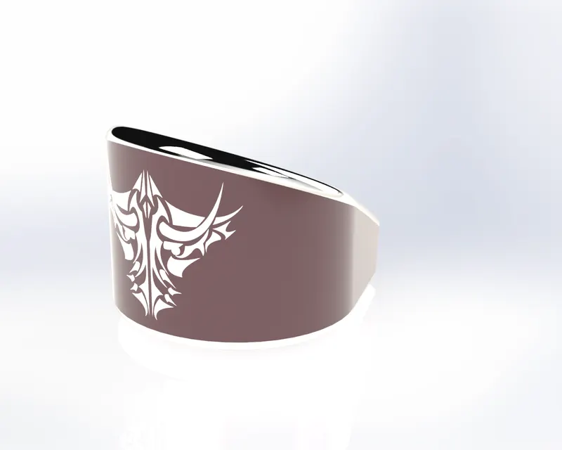
Front fender
it is the part of front wheel
Commands used for front wheel:-
- 2D skecth
- smart diamensions
- revolve
- fillet
- Splite
- Appearance
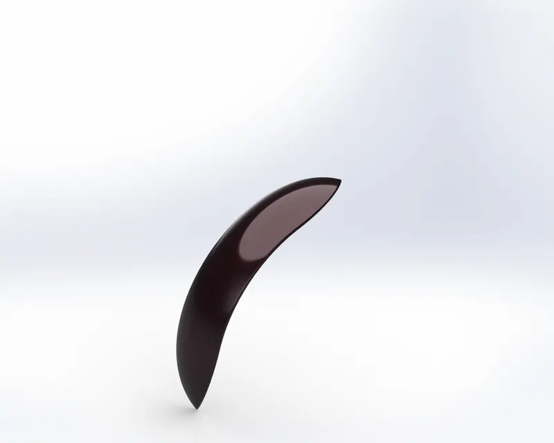
rear fender:-
It is for rear wheel
Commands used for design:-
- 2D skecth
- Smart diamension
- Revolve
- Shell
- Fillet
- splite
- apperance
Image of part
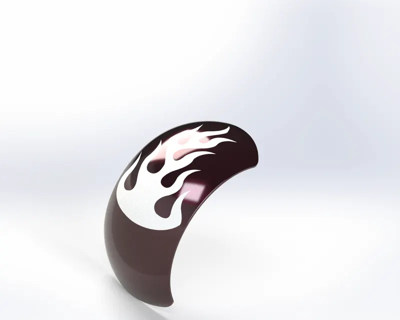
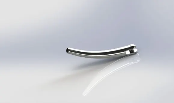
Kick-Stand:- Kick stand also called as the side stand of the bike where it helps the bike to stand on the road when it is in stationary
It is a metal rod attached to the bycical or motorcycal ,it lying horizantally when not in use,that may be cick in to the vertical position to support the vehical when it is stationary.
Command use:-
- 2D skecth
- Smart diamentions
- Extrude Boss/Base
- Extrude cut
- Dome
- splite
- fillet
- Apperance
wheels:-
it is the circular object use to move the vehical over the ground,the object is revolve on axle and is fixed below the vehical
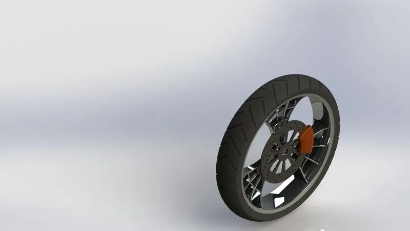
front wheel:-
it consist of following component that need to be designed
- Rim
- Disc brake(rotor)
- calliper
- Tyre
Commands used to designed a front wheel:-
- 2D skecth
- smart diamensions
- Trim intities
- Extrude Boss/Base
- Offset entites
- fillet
- Champer
- Mirror Image
- ExtrudeCut
- Revolved cut
- Circular Pattren
- Revolve Boss/Base
- Combine
- Appearance
Render Image of Front wheel
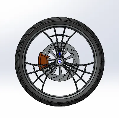
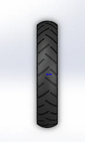
Foure views of font wheel:-
Left view:- Right view:-

Top view:-
 Isometric view:-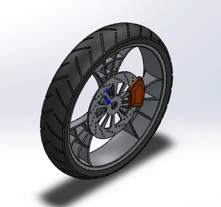
Rear wheel:-
It is the Back part of the vehical.it has following componet
- Rim
- Disc brake(Rotor0
- Calliper
- Tyre
- Sproket
Render Image of part(isometric view)
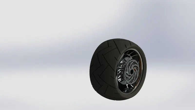
Front view
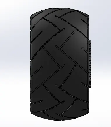
Rigt view
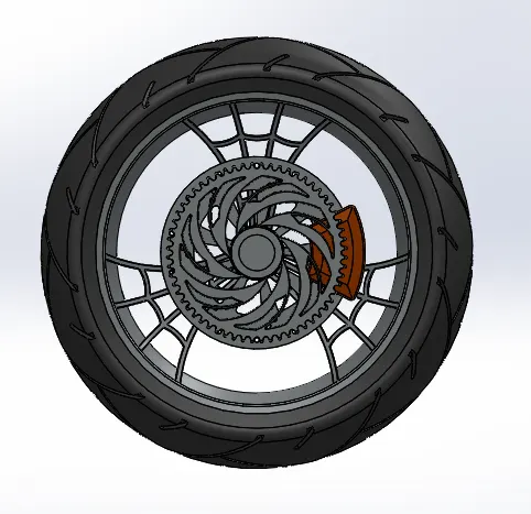
Left View:-
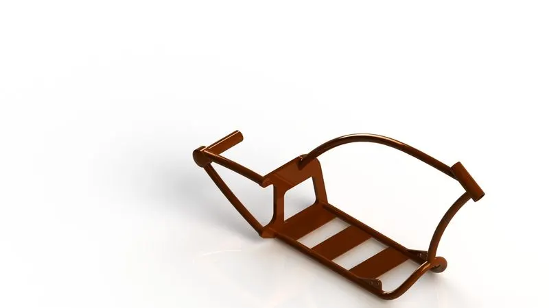
Chassi:-
-It is the vehical frame,
-chassi is the most important part of vehical where every part is fixed such as gear,driver seat,
Commands used to designed the front wheel:-
- 2D skecth
- Smart diamentions
- sweep
- Extrude Boss/Base
- Extrude cut
- Combine
- mirror
Render image of part:-
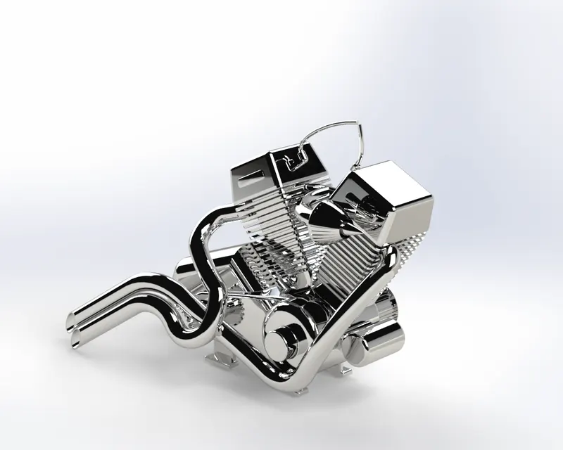
Engine:
a motor cycle power was generated by the engine,and this power was transmited to the rear wheel throw varius mechnical devices.
The most Complicate part in the desined of American chopper is the designed of an Engine.it involved varius projected curves which are very complicated to design
Command used to designed Engine:-
- 2D skecth
- sketch picture
- Smart diamentions
- Extrude Boss/Base
- Fillet
- Trim
- Champer
- Extrude Cut
- Mirror
- Circular Pattern
- Lineer Pattern
- splite
- combine
- Projected curves
- Composit curves
- Swept boss
- Combine
- Dome
- Refrence Plane
- Appearance
Render Image of Engine
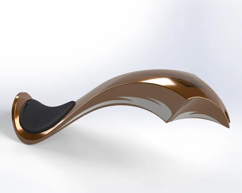
Fuel tank:-
Fuel tank is a safe conatiner of flamable fuel which is used by a engine for generation of power
Command used for desigend a fuel tank:-
- 2D skech
- skecth picture
- smat diamentions
- Trim
- Projected curves
- extrude suface
- surface trim
- swept cut
- splite line
- Refrence plane
- shell
- Mirror
- surface trim
- lofted surface
- Boundry Surface
- Swept surface
- Knite surface
- Appearance and decals
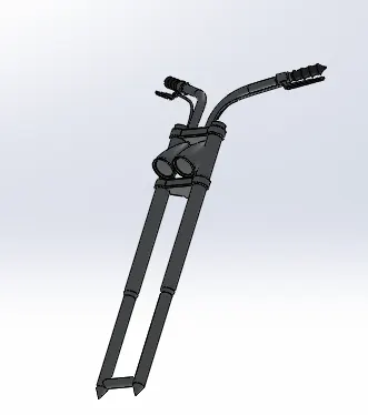
Front Fork:-
A Bicycal Fork is the part of bicycle that hold the front wheel and connects a front wheel and axle to its f frame. a fork typically Consist of tow blades which are joined at the top by fork crown
Commands used to designed a fork:-
- 2D skecth
- Skecth picture
- Smart diamensions
- trim
- Projected curve
- Surface trim
- splite Line
- Fillet
- Shell
- Swept cut
- Extrude surface
- Knite Surface
- Reference Plane
- Lofted Surface
- Appearance
- decals
Image of front fork:-
Assembly:-
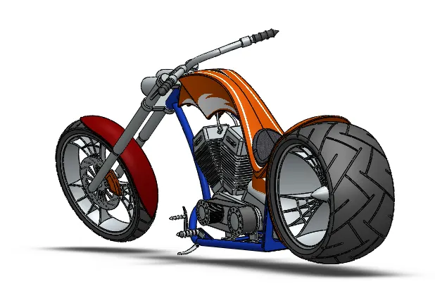
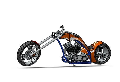
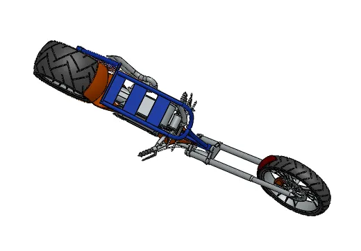
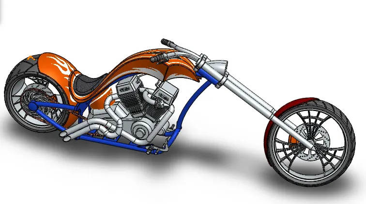
All the above individual parts are assemble together with appropriate joint feature to form the final output of an american chopper bike.
While doing assembly all parts were inserted one by one in the assembly environment and were given manual mates by tacking chassi as the referance so all the parts are move with respect to the chassis.
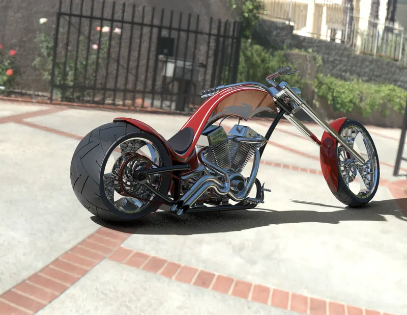
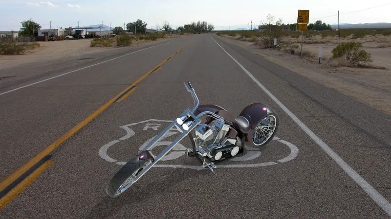
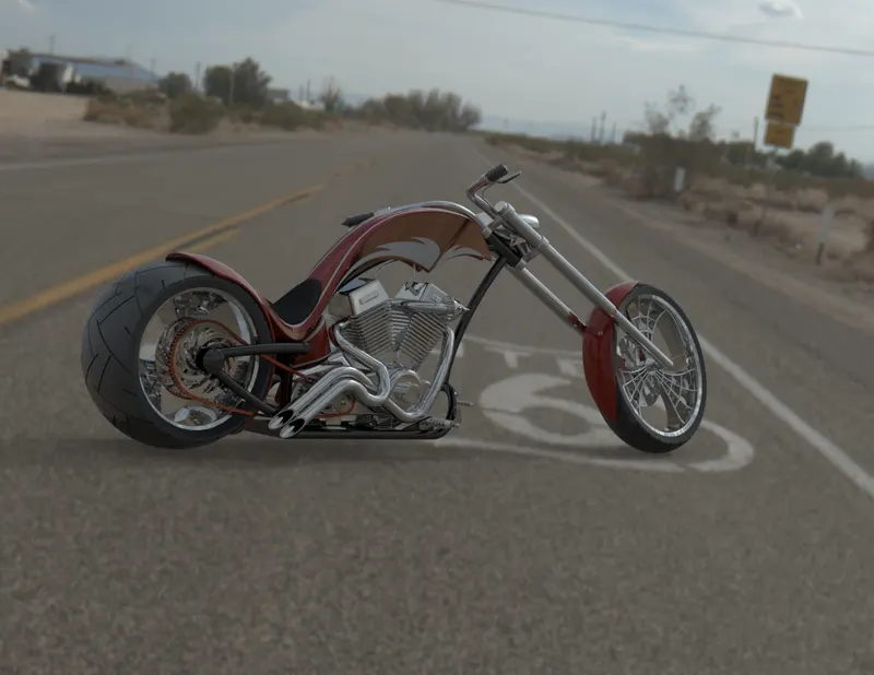
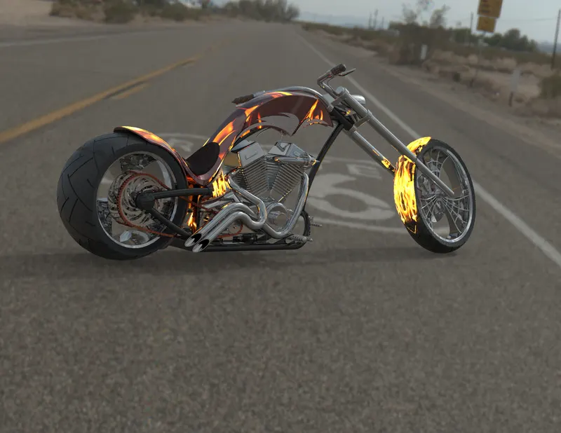
In solidwork we can add the material apperance to each individual part and get the realistic viewing effect using photoview 360 where we can adjust the viewing direction using the camera option and place the model in realistic environment and render the image as show below.
The final out put of American chopper bike show below.
Images of chopper Assembly:-
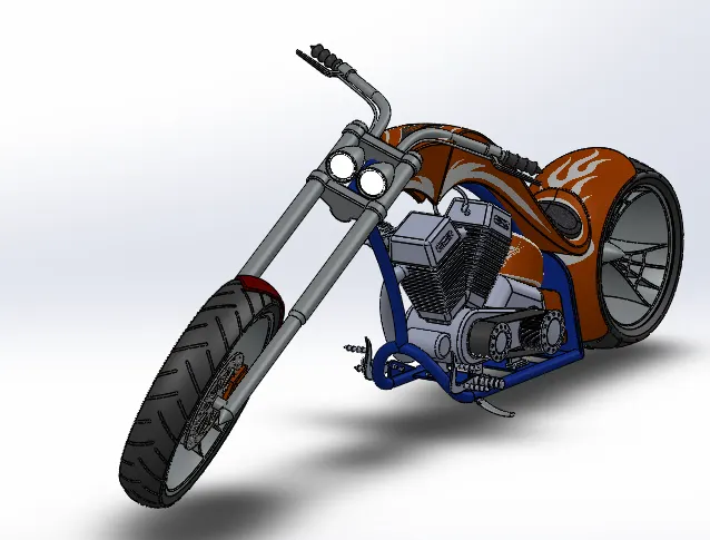
Front View:-
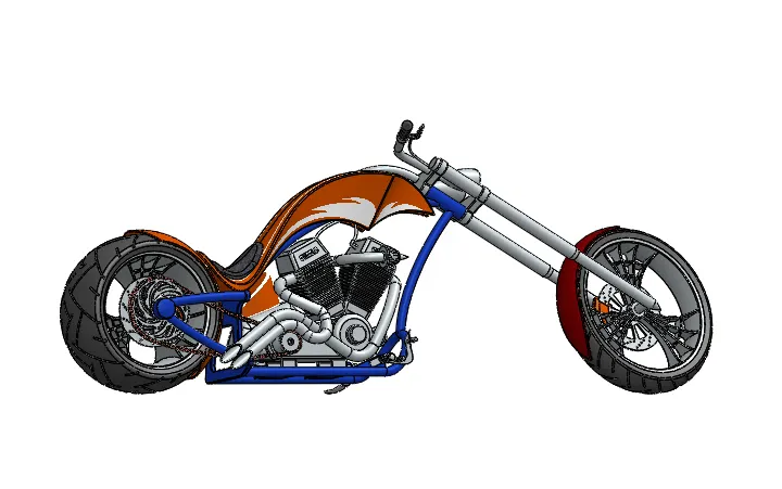
Right View:-
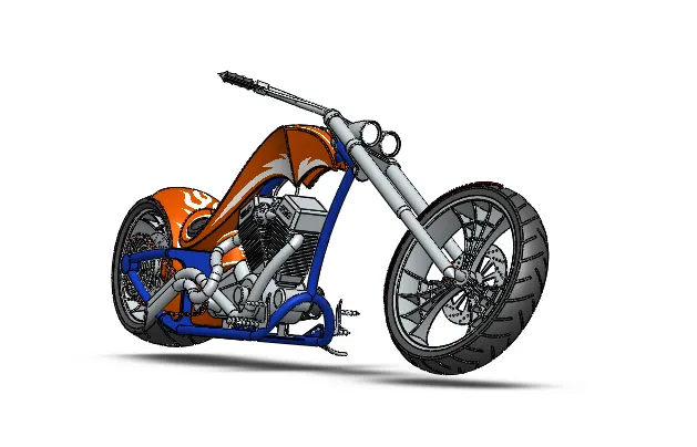
Top View:-
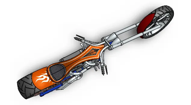
Left hand side view:-
Back view:-
Bottom view:-
Isometric View:-
While doing Assembly Some Parts are re-modelled and adjusted to eliminate the overlapping of the parts with each other.
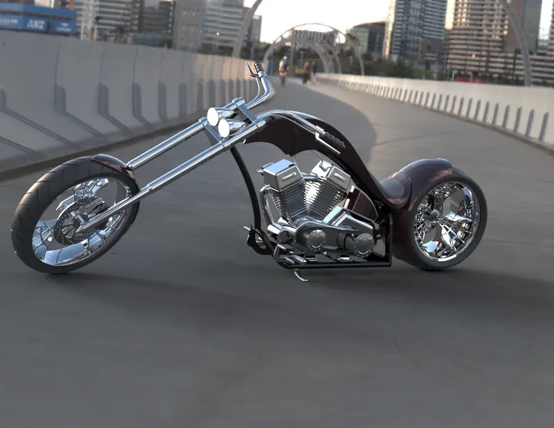
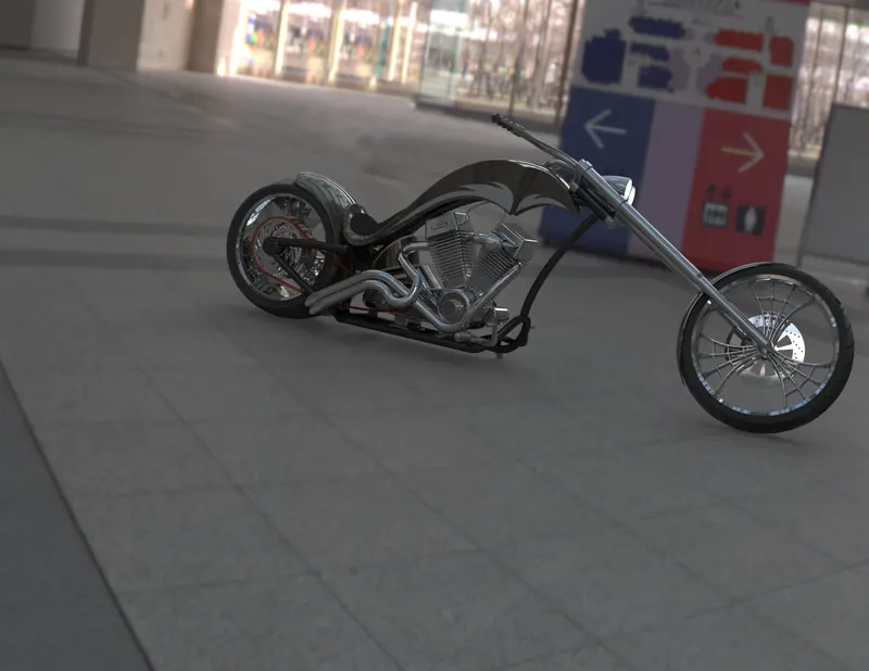
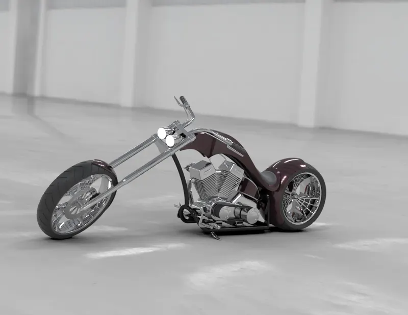
PHOTOREALISTIC RENDERING IMAGES OF AMERICAN CHOPPER
Sunny Drive Way:-
Route 66:-
Dockland bridge:-
Conclusion
all the part of the american chopper were modelled and the assembly was crearted using solidwork and the photorealistic using solidwork and photorealistic render of the chopper were created using solidwork visualise.