Advanced Sheet Metal Design Using NX Cad Challenge_5_Odd Shaped Enclosure
Create Enclosures with Odd Shapes or Angles
Objective – the objective of the project to create odd shapes or angles and convert solid model to sheet metal using NX-CAD.
Introduction – this project is basically a practice project in this project we will learn about how to convert solid body to sheet metal, how to create odd shapes, and angles, use sheet metal features like Sheet metal from solid, add feature like Jog, Bead, Bend, Unbend, Hole, Flat Pattern etc.
Design methodology
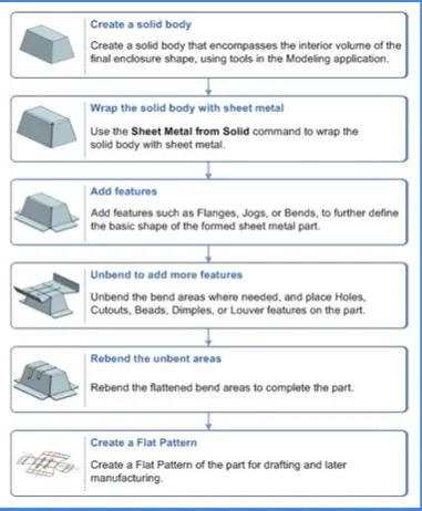
Create Enclosures with Odd Shapes or Angles
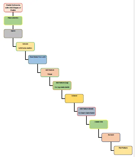
Description
The important tools which used during designing
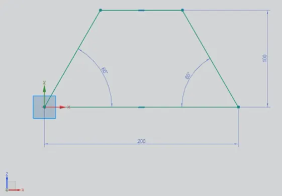
Sketch - This is used to create a basic sketch of the design on selecting the desired plane, then later it can be modeled for the requirement.
The sketch & there dimensional constrains is shows in figure.
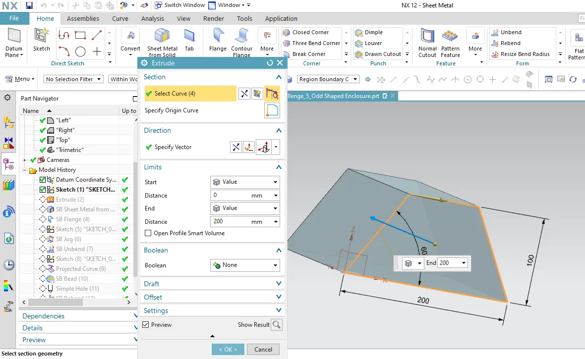
Extrude – Use to Create solid body by extruding a sketch along a vector by a thickness value or adds a material to a plane face.
The thickness of the body is 200mm as shows in figure.
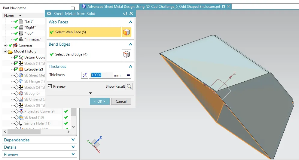
Sheet Metal from Solid – this feature is use to convert solid body to sheet metal Part, basically this feature use to wrap the solid body with sheet or we can say create parallel sheet adjacent to the solid face.
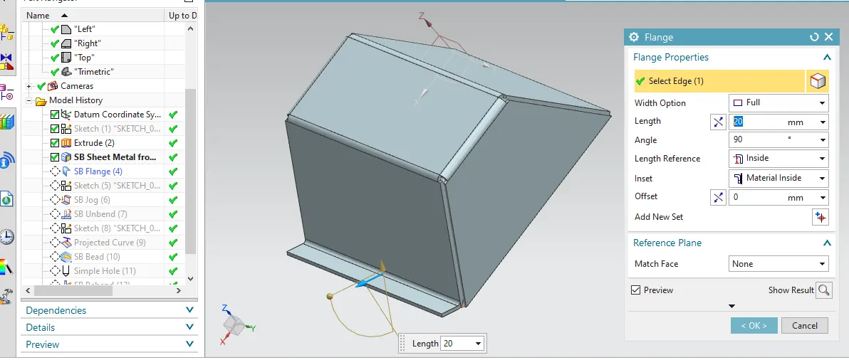
Flange - A flange feature consists of a face and bend connected to an existing face along a straight edge. To add a flange feature, we select one or more edges, and specify the size and position of the material added.
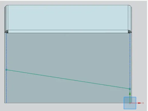
Sketch – Create sketch for Jog
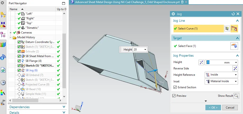
Jog - Jog is a command to lift off one whole side of the part. By selecting a line and the plane, the material can be pushed down or lifted off depending on the situation.
Unbend – It is a powerful tool basically use for analyzing the sheet metal features, dimensions, and also use for creating some features on sheet which is easily create when sheet is flat.
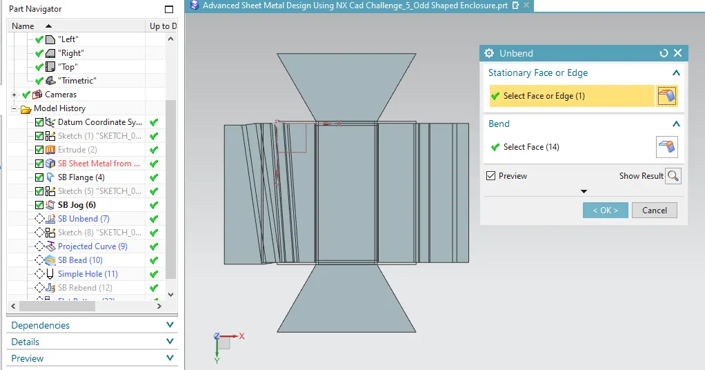
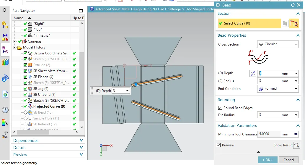
Beads – Bead is similar feature like dimple the only difference is that by using dimple we lift an area while in bead we lift the contour of the sketch. It also added to strengthen the component. beads are also use to give strength and rigidity to the flat sheet.
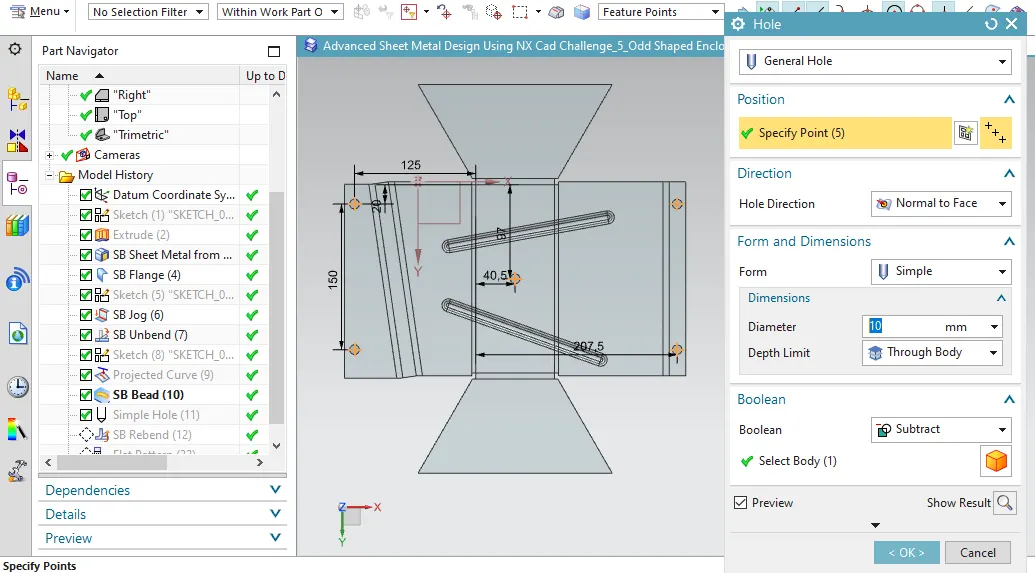
Hole – Hole is a feature which is used to create holes and standard tapping (Metric, BSW, BSP) on the sheet or solid model.
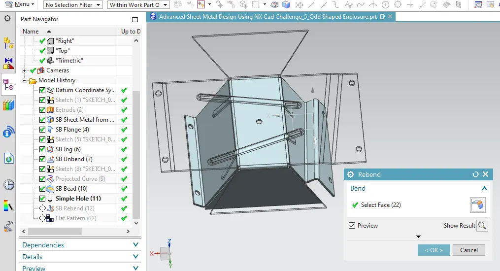
Rebend – Rebend is used to restore the unbend feature to its previous bent state along with any features added after the unbend feature. This is done by using rebend feature and selecting all the bends carefully in order they unbanded.
Flat Pattern - Flat pattern feature allows us to covert 3D sheet metal component into 2D form in Siemens NX software. By using this flat pattern feature we can easily avoid error like interference or collision.
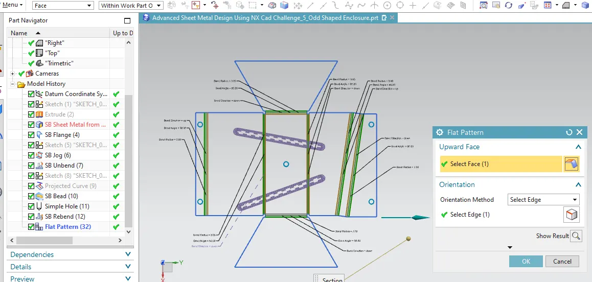
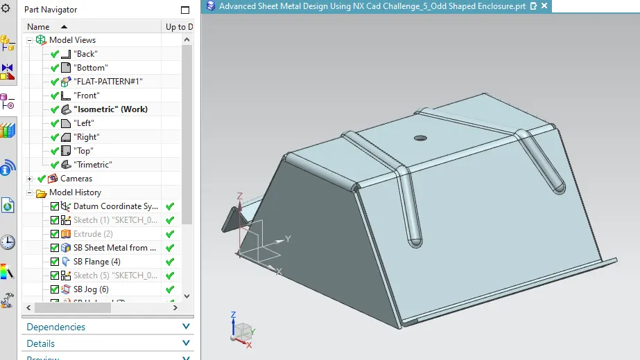
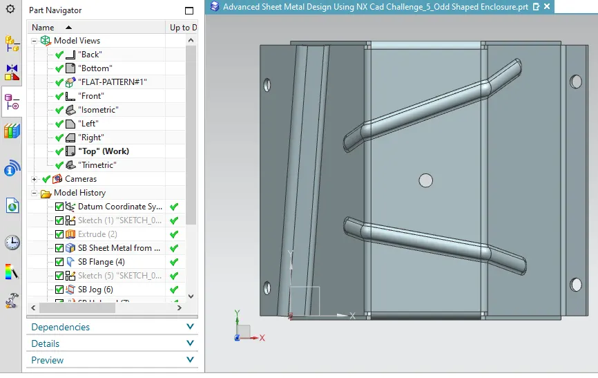
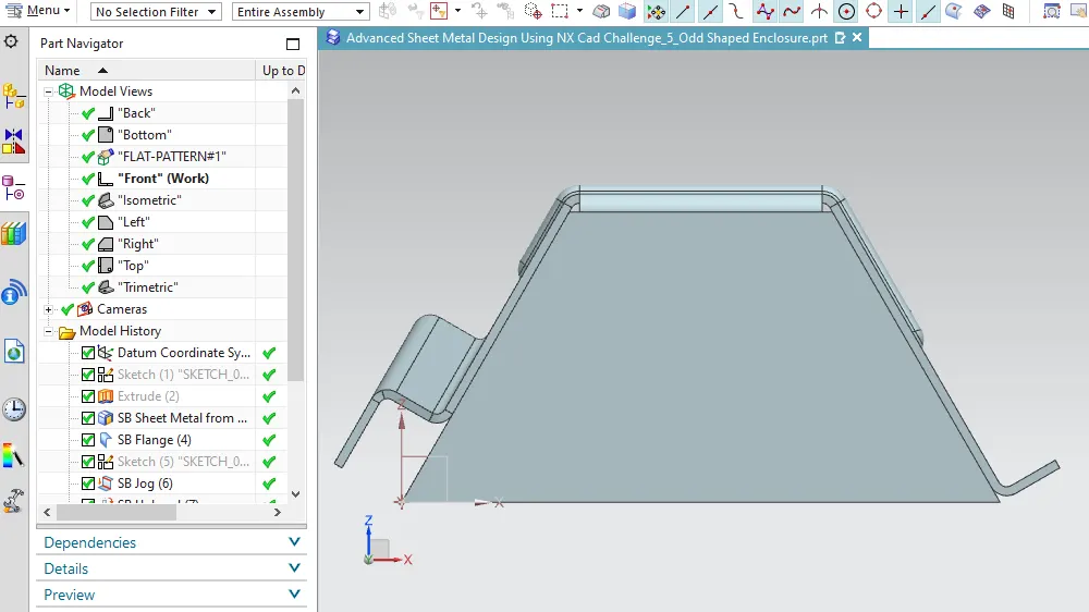
Different views
Isometric View
Top View
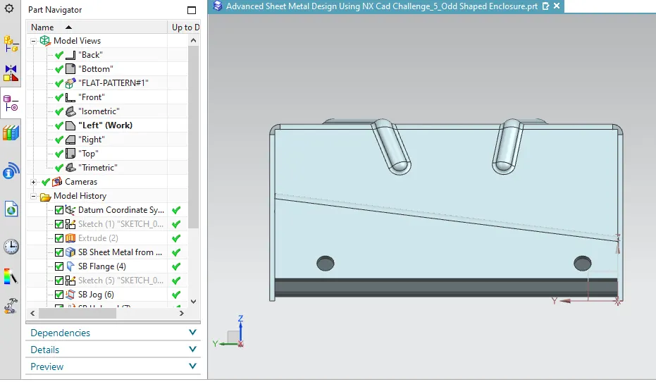
Front View
Side View
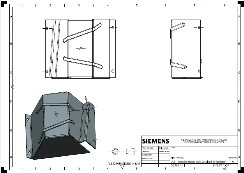
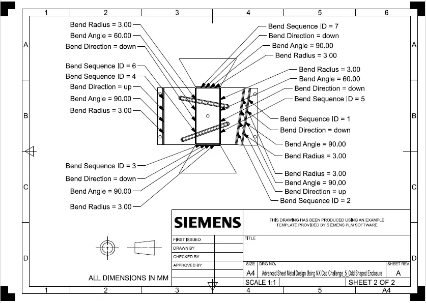
Drafting
Conclusion
1 - We learn about sheet metal workbench.
2 – Commands of sheet metal and how to use it.
3 – Learn designing process of sheet metal component.
4 – By doing this project understand and develop ideas how to proceed to create a sheet metal part. Improve thinking process for developing sheet metal parts.