Roof Design
Roof Design
Introduction
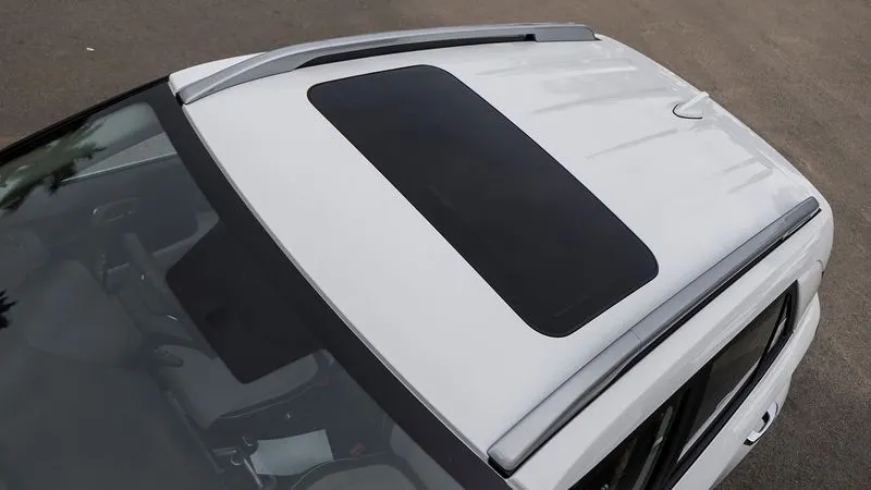
The vehicle roof is the upper most part of the vehicle and is above the passenger compartment
Purpose of roof is protecting the passenger compartment from sun, rain, wind, and external elements.
Aim of project
1 – Learn and understand the design process of roof and its component.
2 – Different considerations of roof design.
A – Visibility criteria (Front and Back)
B – Head room clearance
C – Bow roof positions
D – Strength of the roof we design the roof which withstand (crush test, heat distortion criteria, snow load, rollover test)
E – Moment of inertia of the components
F – Section modulus of roof components
G – feasibility of the design for easy manufacturing of roof and its components
H – Draft analysis
I – Curvature study
Component (reinforcements) of roof
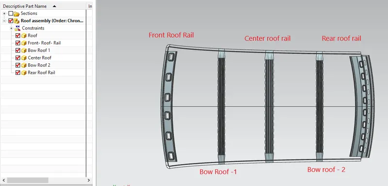
1 - Front roof rail 3 - Central roof rail and
2 - Bow roofs 4 - Rear roof rail
Front roof rail
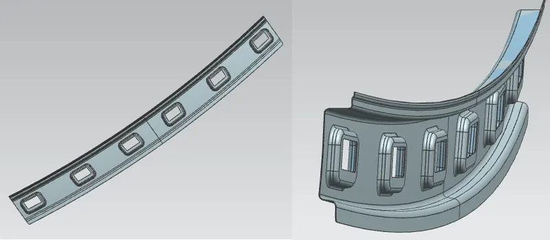
1 - Front roof rail is joining the wind shield glass with roof. It also joins the roof with inner panel and body side outer.
2 - The depth of the front roof rail is based on the front visibility criteria, and width of the front roof rail is decided according to head room clearance.
3 - For joining the front roof rail with flange of roof by using spot welding, and we use mastic for joining the front roof rail with the roof.
Rear roof rail
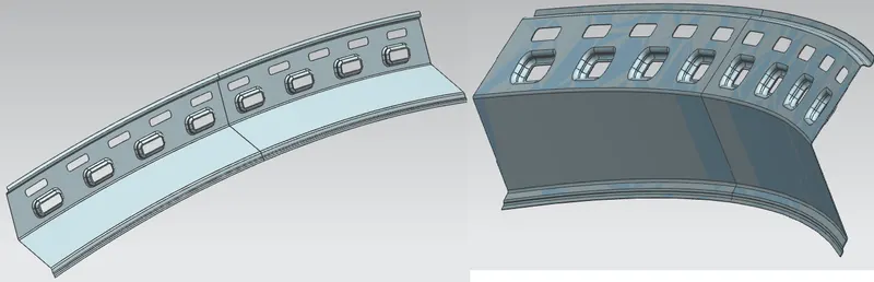
1 - Rear roof rail is joining the back door with roof, and also joins the body side outer.
2 – The design consideration for rear roof rail is rear visibility criteria and rear head room clearance.
3 - For joining the rear roof rail with flange of roof by using spot welding, and we use mastic for joining the rear roof rail with the roof.
Bow roofs
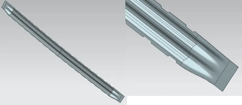
1 - The Bow roofs are given to improve the torsional stiffness and load-bearing capacity of the roof structure, and overall increase the strength of the roof.
2 - The number of bow roofs depends on the overall dimensions of the roof. Longer the roof more the bow roofs are integrated to BIW frame.
3 - The positioning of bow roofs is based on curvature study. The heat distortion criteria and snow load criteria are checked to analyses the position of the bows in various conditions.
4 – The bow roofs are attached to the outer panel using mastic sealants. Each mastic point will have up to 80 mm circular effective area.
Centre roof rail
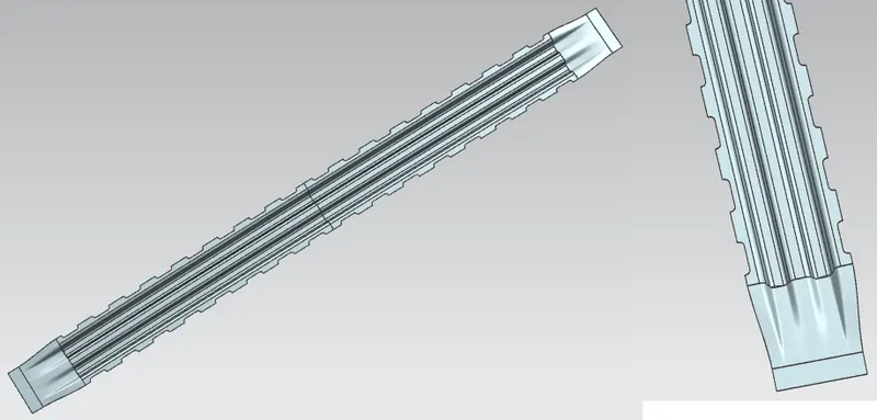
Centre roof rail placed at the center of the roof and connecting the B pillar support structure.
Roof crush test
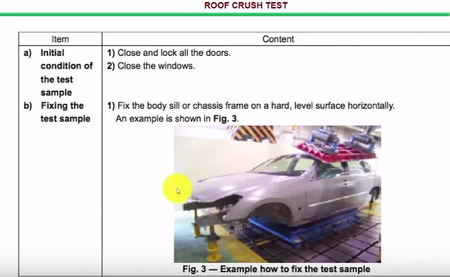
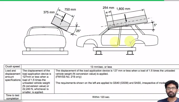
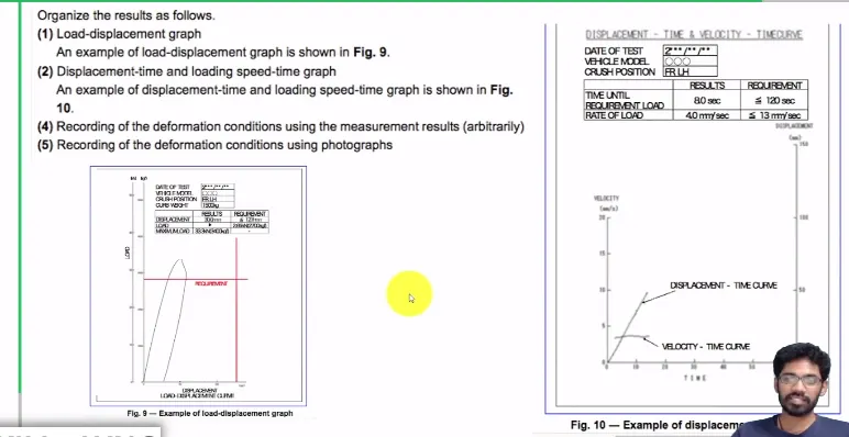
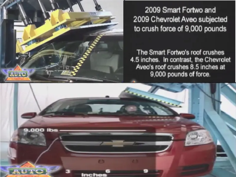
Very important test for roof is role over test for this we do roof crush test.
The regulation for roof crush test is given by institute of highway safety after analyzing so many accidents.
Initial condition for test is
1 – Closed all the doors and windows.
2 – We take only BIW for crush test
If the roof is failed in the crush test, then
1 – We increase the roof thickness
2 – Increase the reinforcements
3 – Increase the thickness of reinforcements
4 – We can change the curvature of roof
5 – Some time increasing the mastic and spot welds also increase the strength
Joining of roof with the roof rails
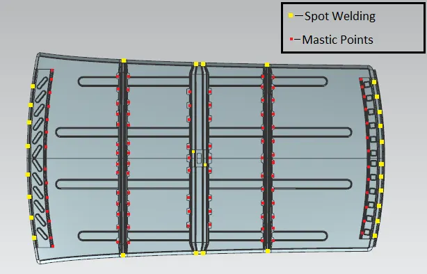
Mastic sealants
Bow roof rails and center roof rail are joined with the help of mastic sealant. here we can not use the spot welding because it damages the styling surface of the roof.
Spot welding
Spot weld are used for joining front roof rail with the roof flange, and also use to joining the rear roof rail with the rear roof flange.
Section modulus
1 - The section modulus value gives us the strength of the component. Strength basically means that whatever load we apply the resistance provided by the component opposite to the deformation of the component.
2 - Bending a steel section that has a larger section modulus than another will be stronger and harder to bend.
3 - In simple terms the section modulus is the ratio of bending moment to bending stress for steel, if your steel has a high section modulus it will be harder to bend and can withstand a high moment without having high bending stress.
There are two types of section modulus
1 - Elastic section modulus
2 - Plastic section modulus
Section moment of inertia
Section moment of inertia is used to predict the amount of deformation and deflection of a part. A higher moment of inertia is preferable as it reduces the amount of deflection for a given force. The thickness of the part and addition of flanges and embosses increase the section inertia of the part. Here the master sections of the roof and roof rails and their section analysis are given.
The elastic section modulus is defined as
S = I / Y
S = Section modulus
I = second moment of inertia (or area moment of inertia, not to be confused with moment of inertia)
Y = distance from the neutral axis to end most point of the fiber.
Solid section inertia for (Front roof rail)
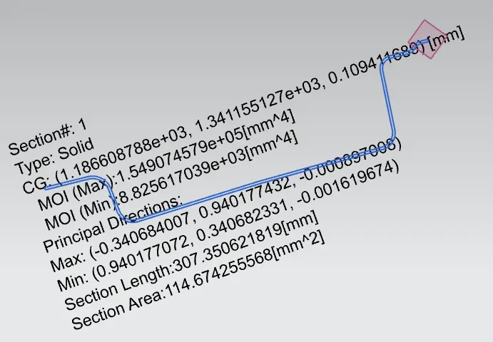
Moment of inertia maximum (I max = 1.54e^+5 (mm^4)
Moment of inertia minimum (I min = 8.82e^+3 (mm^4)
Solid section inertia for (Bow roof rail - 1)
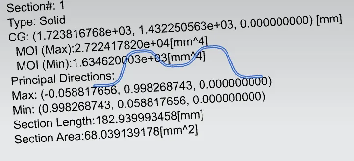
Moment of inertia maximum (I max = 2.72e^+4 (mm^4)
Moment of inertia minimum (I min = 1.63e^+3 (mm^4)
Solid section inertia for (Center roof rail)
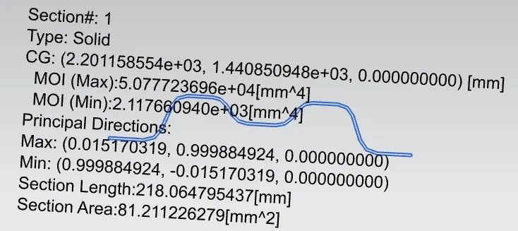
Moment of inertia maximum (I max = 5.07e^+4 (mm^4)
Moment of inertia minimum (I min = 2.11e^+3 (mm^4)
Solid section inertia for (Bow roof -2)
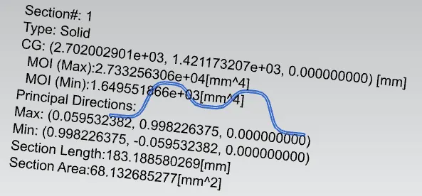
Moment of inertia maximum (I max = 2.73e^+4 (mm^4)
Moment of inertia minimum (I min = 1.64e^+3 (mm^4)
Solid section inertia for (Rear roof rail)
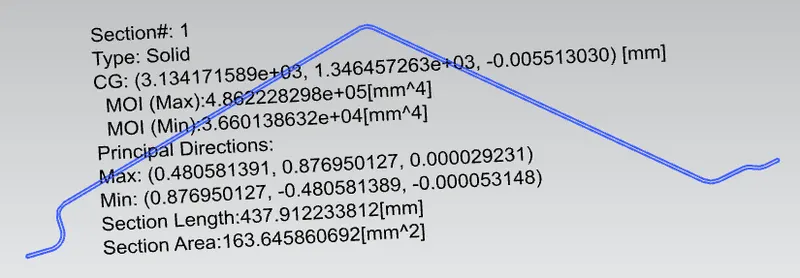
Moment of inertia maximum (I max = 4.86e^+5 (mm^4)
Moment of inertia minimum (I min = 3.66e^+4 (mm^4)
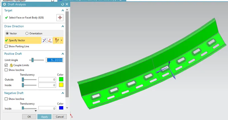
Draft analysis
Draft analysis is done to see the manufacturability of a part, here draft analysis has been done on inner panel, green color indicates that all parts are clearing when core is removed from cavity.
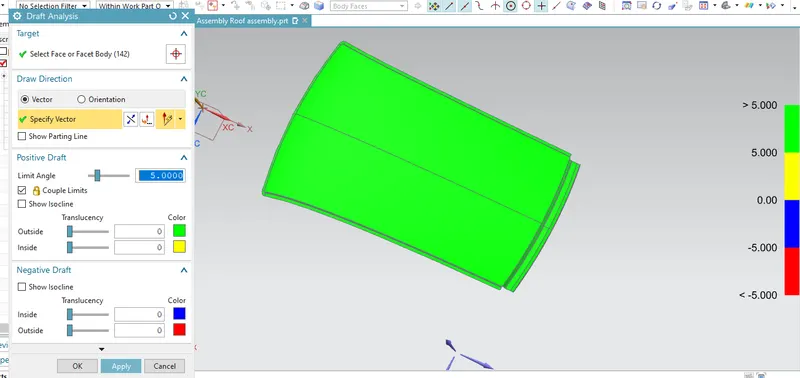
The part has fully constrained like.
A- It does not have any negative draft.
B- How does the part behave.
C- What is going to the constrain whether it is maintain the same radios.
D- You don’t have any undercut in part, you have maintained 3 plus thickness radius.
E- you have minimum hold requirement Gap.
Draft analysis for (Front roof rail)
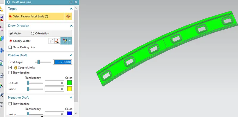
Draft analysis for (Bow roof rail-1)
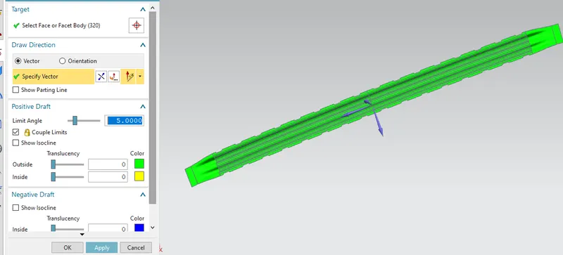
Draft analysis for (Centre roof rail)
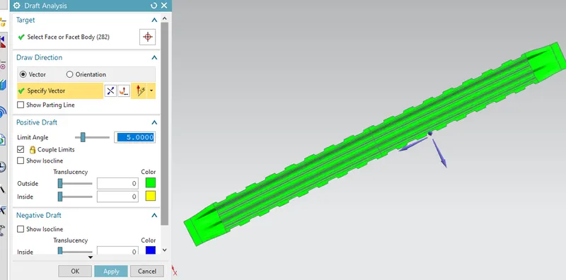
Draft analysis for (Bow roof rail-2)
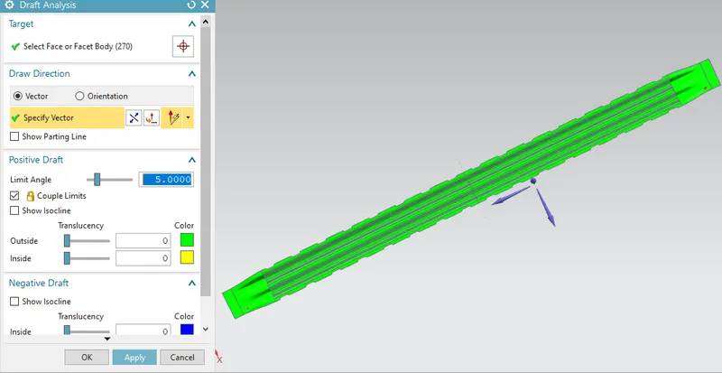
Draft analysis for (Rear roof rail)
Manufacturing process used for roof design
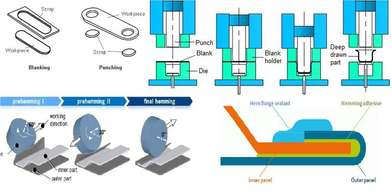
1 – Blanking and Punching 2 – deep drawing 5 – Spot Welding
3 – Hemming 4 – Gluing (Mastic and Hemming glue)
Blanking – Cutting of the Sheet metal along a closed Outline in a single step to separate the piece from the surrounding stock.
Deep drawing – It is the sheet metal forming process in which a sheet metal blank is radially drawn into a forming die by the mechanical action of a punch. The process is considered deep drawing when exceeds its diameter.
Advantage
1- Manufacture the products more quickly and higher quality.
2- More effective and efficient.
Hemming – Hemming is a sheet metal forming process in which sheets are joined by bending over another part in order to achieve a tight fit.
1- Connects two sheet metal part together.
2- Improve the appearance of a part and reinforce part edges.
Gluing (Mastic) – todays we use gluing for sheet metal joining. Best example Roof reinforcements and styling surface joining by Hemming glue, in hemming we use hemming glue for stability and for strong bonding between roof reinforcement and styling surface.
Spot welding - Spot weld is used for joining front roof rail with the roof flange, and also use to joining the rear roof rail with the rear roof flange.
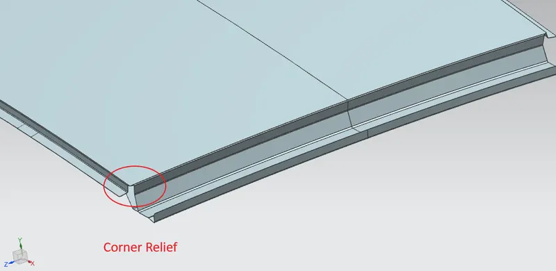
Corner relief
Basically, at the sheet metal operations like (deep drawing and bending, blanking) mostly at the corners stress or strain concentration occurs so that’s we give some relief to the corners for removing these stress and strain.
Heat distortion criteria
Heat distortion temperature is the temperature limit above which the material cannot be used for the structural applications. This study is used to predict the heat distortions temperature at the material where it starts to soften when exposed to a fixed load at elevated temperature. In order to avoid bending or damages on the roof, based on the heat distortion temperature, this study will predict the bow roof position which helps to strengthen the roof.
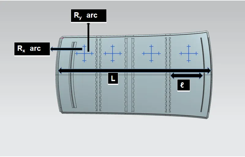
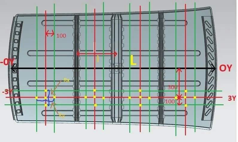
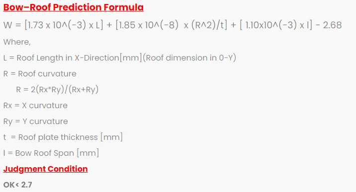

Roof design is passing in heat distortion condition.
Snow load criteria
This test is done to know how is the roof behaving when there is a snow over. normally due to the snow weight the dent will happen. But the roof should be designed in such a way that when the snow is removal the roof should go it its original position. This is the basic requirements for snow load criteria.
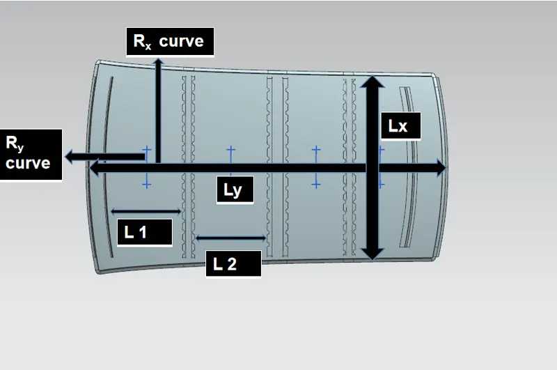
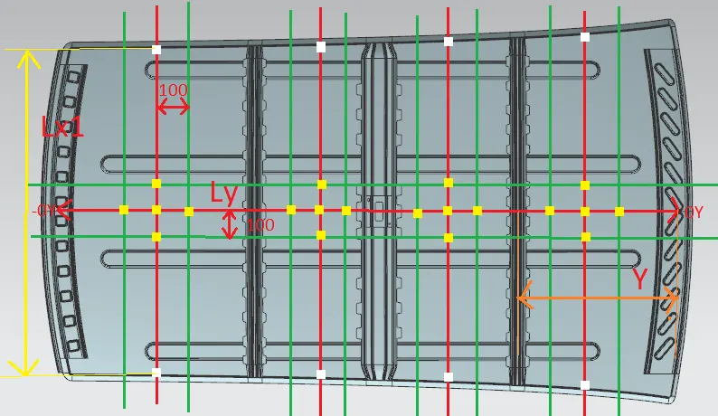
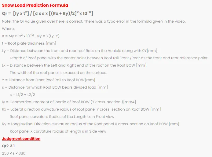
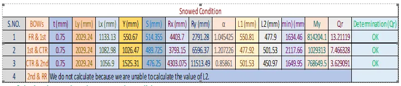
Roof design is passing the snowed condition.
Conclusion
1 – We learn how to solve problems in industries how they think about new projects, what is the approach for designing Car BIW.
2 – We learn about the design parameters of roof like - Visibility criteria (Front and Back), Head room clearance, Bow roof positions etc.
3 – We learn about curvature study. Draft analysis, snow load criteria, heat distortion criteria, about crash test, bow positions, section modulus, solid moment of inertia, manufacturability of my roof, manufacturing processes of roof.
4 – the roof design passing in heat distortion condition, snow load condition, manufacturability of design is possible, roof strength is good,