Week 9 - Challenge 3 - Bumper
BUMPER DESIGN USING CATIA
Aim
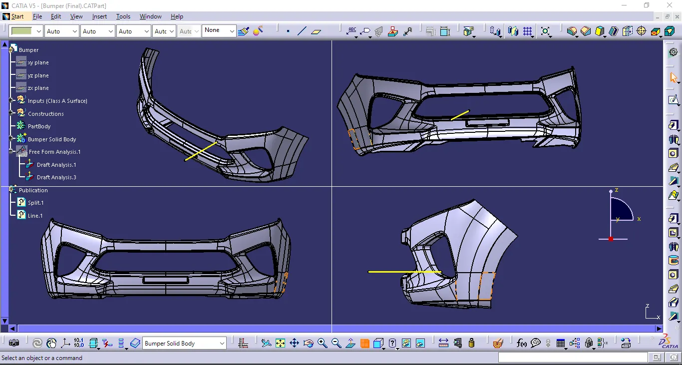
To create the bumper plastic component through the given Class A Surface and to perform draft analysis on the plastic component.
Objective
- Create the Tooling Axis
- Create the Class B and C Surface
- Create the Close Surface
- Perform Draft Analysis
Specification
- Bumper Thickness = 3mm
- Minimum Draft Angle = 3 Degrees
Introduction
Car bumpers are one of the most important exterior parts of a car. It not only has sufficient strength and rigidity, but also acts as a buffer in collision accidents, protects the body.
The purpose of bumpers is to reduce or prevent physical damage to the front and rear of vehicles in low-speed crashes. By design, bumpers protect the hood, trunk, grille, fuel, exhaust, and cooling system. It absorbs shocks from car accidents.
Production Standards
The standard requires protection in the region 16 to 20 inches above the road surface. It also says the front and rear bumpers should prevent damage at barrier impact speeds of 2.5 mph across the full width and 1.5 mph on the corners.
Why be use plastics in bumpers?
- Plastic is lighter and more aerodynamic than metal, resulting in increased fuel economy.
- Plastic is also safer than metal as a bumper material since it absorbs more of the impact during an accident.
Material Used For Bumper
PC (Polycarbonates)
Characteristics: great rigidity, hardness, and durability, and very resistant to impact. Good resistance to weathering and are easier to repair than other types of plastic (good performance for painting and welding). Capable of withstanding temperatures of up to 120°C
Uses: spoilers and corner protectors, grilles, bumpers, etc.
PE (Polyethylene)
Characteristics: highly elastic on impact and easy to recover their original shape. Great performance against heat and a wide variety of chemical agents. Used also in the production of electrical components. They can begin to deform from 87°C.
uses: ducts, batteries, wheel arch liners, bumpers, etc.
PP (Polypropylene)
Characteristics: with better performance against traction, shock absorption and heat (up to 130°C). It also provides great elasticity and rigidity, and good performance against chemical agents.
uses: ducts, batteries, wheel arch liners, bumpers, etc.
PP – EPDM (Ethylene Propylene Diene Monomer)
EP (Epoxy Resin)
Advantages over other materials
- Less weight: the increase in the size of vehicles and the increase in the number of parts used in their manufacture make it essential to use materials that help to reduce the total weight of the vehicle.
- Reduction in consumption: this reduction in weight also leads to a reduction in consumption, resulting in savings of around 0.5 liters per 100 km.
- Environmental impact: lower consumption in turn leads to a reduction in emissions, an essential aspect today to comply with current regulations. In addition, it is a material that can be recycled, extending its useful life.
- More complex design lines: These allow the design of panels with complex geometries, which also influences the dynamic performance of the bodywork.
- Good thermal, electrical and acoustic insulation performance: This enables running comfort and better shock absorption at low speed because of their greater flexibility.
- No rusting.
- Reduction of cost and time in the assembly process.
Disadvantages of the use of plastic
- Less resistant to weathering: prolonged exposure to the weather can cause degradation of the material, resulting in a loss of gloss and strength of the exposed plastic.
- Increased sensitivity to chemical agents: some plastics have a lower chemical resistance to some products such as solvents, which can damage the plastic substrate.
- Less adherence and incompatibility with some paints: due to the features of certain plastics, it is advisable to use specific paints to ensure better adhesion.
Manufacturing Process for Car Bumper
A car bumper is made by a process called reaction injection molding (RIM), which basically consists of making a special polyurethane compound and introducing it into a large bumper moulding. RIM is a process that conserves raw materials and reduces costs. It is similar to injection molding except thermosetting polymers are used, which requires a curing reaction to occur within the mold. Common items made via RIM include automotive bumpers, air spoilers, and fenders.
Design and Analysis of Automobile Bumper
<!-- [if !supportLists]-->1. <!--[endif]-->Create the Tooling Axis
<!-- [if !supportLists]-->2. <!--[endif]-->Draft Analysis
<!-- [if !supportLists]-->3. <!--[endif]-->Creating Class B and C Surface
<!-- [if !supportLists]-->4. <!--[endif]-->Create the Close Surface
<!-- [if !supportLists]-->5. <!--[endif]-->Solid Body Creation
<!-- [if !supportLists]-->6. <!--[endif]-->Perform Draft Analysis
Objective of the project
<!-- [if !supportLists]-->1. <!--[endif]-->Learn how to create tooling axis and what is its significance of tooling axis in plastic component design.
<!-- [if !supportLists]-->2. <!--[endif]-->Learn draft analysis of master surface (A Surface).
<!-- [if !supportLists]-->3. <!--[endif]-->Learn how to create required surfaces (B Surface and C Surface) using given master surface (A Surface).
<!-- [if !supportLists]-->4. <!--[endif]-->Learn how to create thick body from the close surface.
Steps follows
<!-- [if !supportLists]-->1. <!--[endif]-->Check the connectivity of the class A, ensuring that no gap between two surfaces.
<!-- [if !supportLists]-->a) <!--[endif]-->Using Join command
<!-- [if !supportLists]-->b) <!--[endif]-->boundary command – to check the boundary of the A surface
<!-- [if !supportLists]-->2. <!--[endif]-->Find the tooling axis of the component
<!-- [if !supportLists]-->a) <!--[endif]-->Tooling axis is the direction at which the mold open & core & cavity opens.
<!-- [if !supportLists]-->b) <!--[endif]-->Analysis the component & find which is the best tooling direction (X, Y, Z)
<!-- [if !supportLists]-->3. <!--[endif]-->Draft analysis (Insert – Analysis – Feature Draft Analysis)
<!-- [if !supportLists]-->4. <!--[endif]-->Create B Surface
<!-- [if !supportLists]-->5. <!--[endif]-->Create C Surface
<!-- [if !supportLists]-->6. <!--[endif]-->Join A Surface with B, & C Surface & create a closed Surface.
<!-- [if !supportLists]-->7. <!--[endif]-->Using close surface command Create Solid Part.
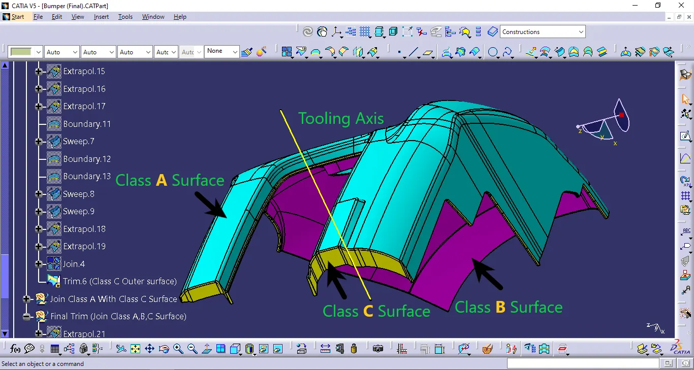
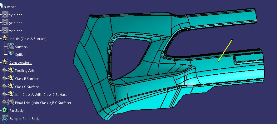
A Surface is the surface that is created by the concept sketches made by free hand sketchers. this computerized design is known as Class A surface.
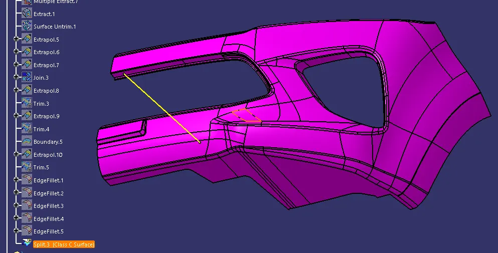
B Surface is created by using class A surface, and the distance between A surface and B surface is equal to the thickness of the part, it is also called engineering surface.
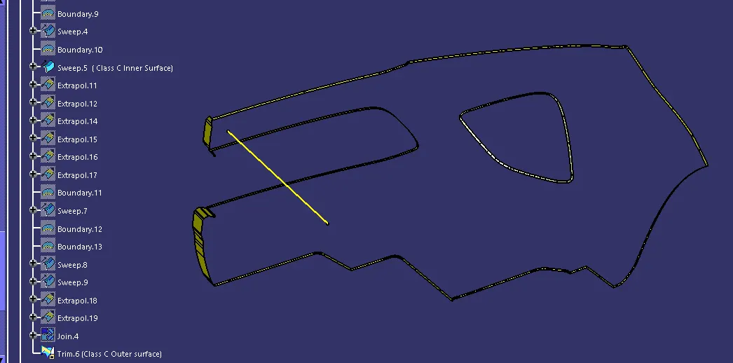
C Surface is created for connect Class A and Class B surface also known as the side wall of the surface.
Tooling axis
Tooling axis is the direction at which the mold open & core & cavity opens.
Analysis the component & find which is the best tooling direction (X, Y, Z)
Draft analysis
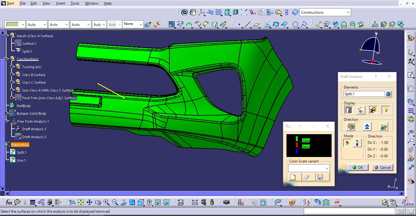
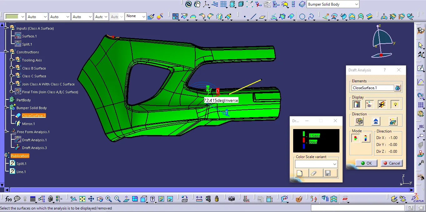
Draft analysis is done to see the manufacturability of a part, green color indicates that all parts are clearing when core is removed from cavity.
The part has fully constrained like.
<!-- [if !supportLists]-->1. <!--[endif]-->It does not have any negative draft.
<!-- [if !supportLists]-->2. <!--[endif]-->How does the part behave.
<!-- [if !supportLists]-->3. <!--[endif]-->What is going to the constrain whether it is maintain the same radios.
<!-- [if !supportLists]-->4. <!--[endif]-->You don’t have any undercut in part, you have maintained 2.5 plus thickness radius.
<!-- [if !supportLists]-->5. <!--[endif]-->You have minimum hold requirement Gap.
Command used in CATIA
<!-- [if !supportLists]-->1. <!--[endif]-->POINT
<!-- [if !supportLists]-->2. <!--[endif]-->LINE
<!-- [if !supportLists]-->3. <!--[endif]-->PLANE
<!-- [if !supportLists]-->4. <!--[endif]-->INTERSECTION
<!-- [if !supportLists]-->5. <!--[endif]-->EXTRACT
<!-- [if !supportLists]-->6. <!--[endif]-->UNTRIM
<!-- [if !supportLists]-->7. <!--[endif]-->EXTRAPOLATE
<!-- [if !supportLists]-->8. <!--[endif]-->TRIM
<!-- [if !supportLists]-->9. <!--[endif]-->OFFSET
<!-- [if !supportLists]-->10. EDGE FILLET
<!-- [if !supportLists]-->11. BOUNDARY
<!-- [if !supportLists]-->12. SWEEP
<!-- [if !supportLists]-->13. JOIN
<!-- [if !supportLists]-->14. <!--[endif]-->CLOSE SURFACE
<!-- [if !supportLists]-->15. <!--[endif]-->DRAFT ANALYSIS
<!-- [if !supportLists]-->16. PUBLICATION NEERAJ SINGH
Class A Surface
Class B Surface
Class A Surface
Draft Analysis
Closed Surface
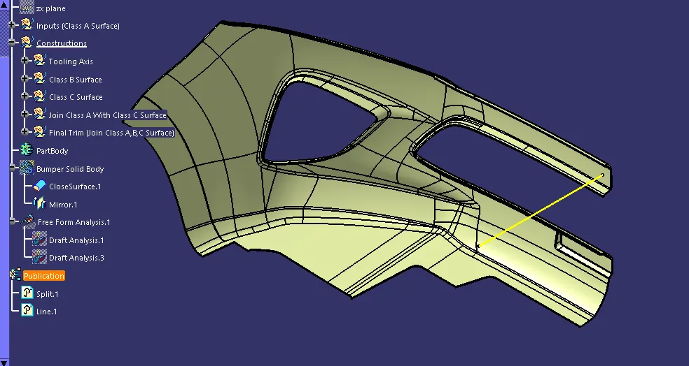
Solid Body