Advanced Sheet Metal Design Using NX Cad Challenge_2_Box Assembly
Title of Project –
Advanced Sheet metal design using NX CAD – Box Assembly
Objective –
TO design a sheet metal box assembly using Siemens NX Sheet metal application.
Introduction –
NX sheet metal design incorporates material and process information in sheet metal-specific modelling features: bends, flanges, tabs, cut-outs, beads, dimples, louvers, corner and edge treatments, patterns and other formable features.
Design Methodology –
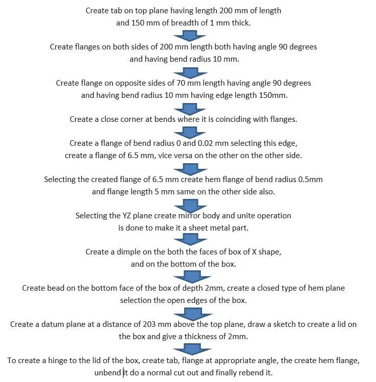
Flow chart -
Features used –
- Sketch – It’s the base 2D drawing where it’s drawn on selecting a plane.
- Tab - It’s base feature part of the sheet metal.
- Flange -Its extended part of sheet metal obtained by selecting edges.
- Unbend – this feature unbends the sheet metal part selecting any face as stationary face.
- Rebend – It brings back the sheet metal to its original shape.
- Dimple – It’s a kind of die press applied on sheet metal to obtain the required to obtain the desired shape.
- Bead - This feature gives strength to sheet metal part.
- Hem flange – It modifies the edge of sheet metal by folding it over onto itself.
- Mirror Feature – created the exact mirror sheet metal part when given a reference plane.
- Normal cut out - Cuts material by projecting a sketch onto a model and then cut perpendicular to faces intersected by projection.
- Closed corner – Closes corner where two adjacent flanges meet by extending the bends and flanges.
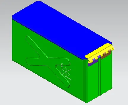
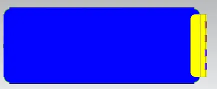
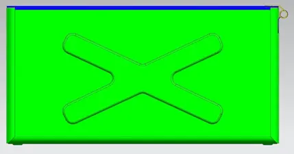
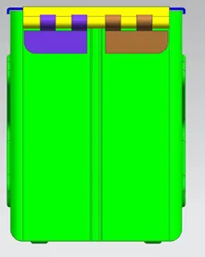
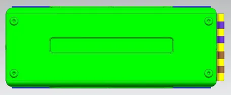
Various views of sheet metal casing –
Conclusion –
By performing this sheet metal modelling, I have learned to use and apply various features like tab, flange, bend, normal cut-out, closed corner, mirror feature, dimple, bead, unbend, rebend.