Design of backdoor
Aim -Tail Gate Design-
About –
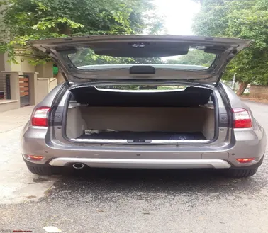
A tail gate is also called as hatch. Its usually a door at rear vehicle that can be opened and closed.
It’s mounted on the rearrest part of 4-wheel car with the help of hinge. It’s connected to gas stay or electric motor drive for easy opening or closing over the sides. On the bottom portion of the door inner panel there is latch and striker mechanism which helps in the door to be held firmly when closed. On the outside sheet metal part indicator and backlight is mounted for signalling the rear drivers. The door when closed the sealing flange goes and sits on the rubber sealant on the inner body panel tightly closes to prevent fluids entering inside. It also has rear wiper for proper rear viewing for driver.
Material used –
Tailgates are usually stamped with steel deep drawing sheets, thickness varying in between 0.6 mm to 8 mm for both inner and outer panel. The inner panel are reinforced, embossed for giving strength. Usually by hemming the outer and inner panel are made to hold together.
Aluminium material is also used to create backdoor. This is bit expensive than steel.
Tailgate consists of -
- Upper outer panel
- Lower outer panel
- Inner panel
- Hinge reinforcements (LH & RH)
- Gas stay reinforcements (LH & RH)
- Latch & striker reinforcements
- Wiper motor reinforcements
Some of the features used in designing Tailgate assembly are,
- Offset surface – creates a body by offsetting a set of faces.
- Trim sheet – trims of a portion of sheet body.
- Law extension – from the edge of sheet metal/ curve a extended sheet metal is created.
- Curve on surface – creates a surface spline on the face of sheet metal.
- Mirror Geometry - creates the exact mirror of sheet metal body.
- Face Blend – adds tangent blend faces between selected set of faces.
- Edge Blend – rounds sharp edges between the faces.
- Projected curve - projects the curve, edges, points on planes or on faces.
- Emboss – modifies a body with faces made by projecting a section along a vector.
- Extend sheet – extend a sheet body by a distance.
- Sew – combines two adjacent sheet bodies making it as one.
- Through Curves – creates a body through multiple sections where the shape changes through pass through each section.
- Sweep – creates closed smooth surface along the given curve edge and guides.
- Hemming – sheet metal joining process in which sheets are joined by bending it to 180 degrees.
Explaining overall design process –
- Basically, the whole class A surface obtained from styling team is taken into consideration for reference for making the inner panel. It is having two surfaces like outer panel upper panel & outer panel lower body.
- The surface irregularities are checked if needed they are rebuilt and sewed, if there are any major changes to be done its reclarified with the styling team.
- First of all, tooling direction is set which helps us to make lot of design considerations easier and as well also for fabrication/manufacturing purpose.
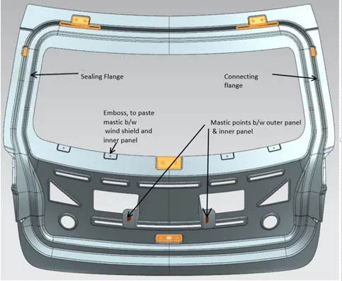
- Taking that into consideration of the outer surface the Sealing flange is designed, it sits on the rubber sealant liner on the tail gate preventing the rain water flowing inside. Also helps in tight seal at the back.
- Then the connection flange is obtained by law extending the sealing flange edge and extracting outer panel considering the tooling direction finally the necessary parts are trimmed and extended.
- By taking the reference of outer panel its offset by 1mm below and the sheet metal part is designed in such a way that the rear-view and the wind shield glass should have enough space.
- In order to accommodate tail lamps, the inner panel is designed to have a gap between the outer panel and inner panel. Necessary cuts are made on inner panel for proper housing and electrical wiring.
- In order to join and strengthen the outer panel locally mastic sealants are applied on to the extended sheet. Mastics are resin paste which hardens after heat treating.
- Necessary cuts outs & embosses are done on to the to the inner panel to make it lighter and provide stiffness to the tail gate.
- For the emboss there is 7 degree or more draft angle for proper movement of the tool.
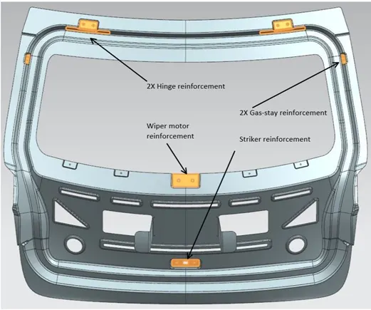
- For wiper motor to accommodate the emboss is done in tooling direction and the surface is flat. In order to strengthen a reinforcement of 1.5 mm thickness is given.
- Beside the wiper motor the emboss are given because here the mastics sealants are applied between the inner panel and the rear wind shield glass.
- For the hinges to mount properly on inner panel the hinge mounting area are made flat, and reinforcements are given for strength.
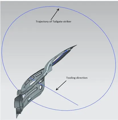
- Taking the LH and RH hinge position the centre axis line is drawn between the hinges for the trajectory which is helpful in the proper positioning and placement of latch.
- The latch will also under go so much of load (while opening and closing) so reinforcement is given for strength. The latch mounting is done above the sealing flange taking into consideration if done below the rain water might enter into luggage room.
- For Gas stay the mounting surface is made flat where the mounting of gas stay comes and sits on it. There is reinforcement given so that the gas stay mounting will also have strength when it’s subjected to open and close of tail gate.
- Hemming process is done on the outer and inner panel where the outer panel upper part is trimmed and bent 180 degrees on the inner panel upper part which clings on to it. Rubberised sealants are pasted in the gaps.
- Above same process is followed for the lower tail gate panel part.
Different parts constituting the tail gate -
- Upper outer panel – it gives the aesthetic looks to the upper part to the tailgate door and houses rear lights in it.
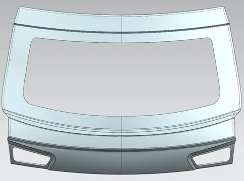
2. Lower Outer panel – It gives the aesthetic looks to the lower part of tail gate.
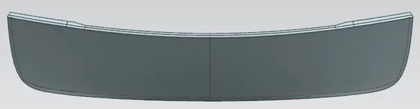
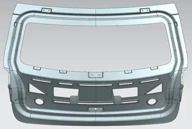
3. Inner panel – It’s the inner panel of tailgate which has hinge reinforcements, gas stay reinforcements, wiper motor reinforcement, striker reinforcement, and houses various emboss for the strength of inner panel. And the cut outs are done for the reduction of the total weight of tailgate.
4. Latch and striker direction w.r.t to hinge axis, tooling direction – it tells the trajectory in which the tailgate opens and closes . The tooling direction gives the direction in which the drawing process takes place.
5. Reinforcements – It gives localised strength to hinge, gas stay, wiper motor, striker.
6. Hemming of outer and inner panel – outer panel with inner panel is joined in which sheets are joined by bending it to 180 degrees and relief radius is 3mm.
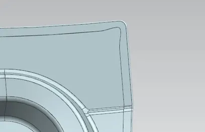
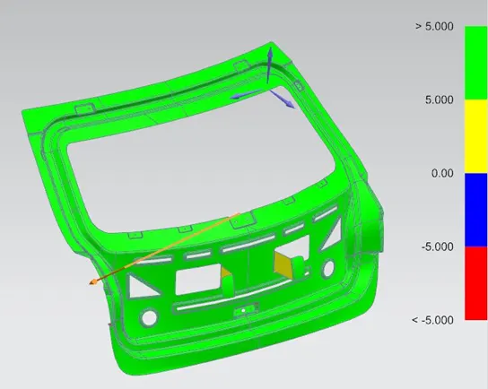
7. Draft analysis – it is carried out to obtain visual feedback on draft condition of the part. It tells us the optimum die press direction. It avoids die lockdown situations make decisions on appropriate parting line also suggestions on cutter sizing for machining and other purposes. Green colour tells that die press direction is optimum direction.