Photo Realistic Rendering
Title – Report on Design of American Chopper.
Objective – The main objective is to learn how to model a part, assembly of created parts and to create a photo realistic view using photo view 360* & visualise in SolidWorks.
Introduction – It contains detailed explanation of designing an American chopper from sketch to final finished model of Chopper. Steps involved are,
- Design of various individual parts.
- Assembly of various parts with proper mates.
- Application of decals setting up scenes, lights and camera.
- Finally rendering.
Design Approach -
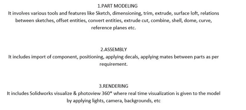
Features/Sketch Entities –
- Sketch – It’s a 2-dimensional representation of the model with respect to plane/view. There are different known entities of sketch like arc, spline, circles, rectangle.
- Extrude boss/base – Is a type of feature which converts 2D sketch into 3D solid body.
- Offset – Its used to create a copy of sketch entities, edges at certain specified distance.
- Fillet – Is used to create a smooth surface on sharp corners, edges of a solid bodies.
- Lofted boss/base - This feature is used to generate a complex geometry in single feature. It is done by interpolating surface between various cross section of a model.
- Dome - Is used to create a bulged kind of surface outside a surface by diving the specified dome height.
- Extrude cut – This feature allows to remove the material from 3D body for given dimension. It’s used to create holes, slots, channels etc.
- Split - This feature to project an entity (sketch, solid, surface, plane) onto another surface or curved /planar surface. And also, able to split a single body int two separate bodies.
- Revolve – This is used to create a revolve feature in which a sketch contains one or more profiles with line, edges, centreline on which the revolve is done.
- Trim – This feature is to remove unwanted sketches to obtain a complete closed sketch/ profile.
- Mirror – This feature is used to obtain exact copy of selected body, with reference to selected plane or face.
- Combine – This feature is used to make two different bodies as one.
- Shell – Its used to define the thickness of thin or thick shell elements.
- Chamfer - This is used to obtain angular cut on the edge of solid body.
- Circular Pattern – This feature is used to obtain N number of instances circularly over a selected, face, body.
- Linear Pattern – This feature is used to obtain N number of instances linearly over a selected surface, face, body.
- Lofted surface – Surfaces are generated by multiple 3D curves or existing edges creating a smooth tangency between the selected curves.
- Swept surface – Surface that are generated from a section curve positioned along a path.
- Filled surface – This feature constructs a surface patch with any number of sides within a boundary defined by existing model edges, sketches or curves.
- Extend surface – This feature is used to extend a already created surface by specifying a certain distance.
- Surface trim – This is used to remove material from surface. This is divided into 2 types standard and mutual.
- Surface knit - It is used to stitch the two surfaces and reduce the gap between two surfaces.
- Appearance – This defines the visual properties of a model including colour and texture. This does not affect the physical properties of a material.
Parts Modelled for American Chopper -
- Transmission Belt
- Kickstand
- Front Fender
- Rear Fender
- Chain
- Oil Tank
- Pedal
- Front Wheel
- Rear Wheel
- Front Fork
- Chassis
- Engine
- Gas Tank
Description of parts and features used -
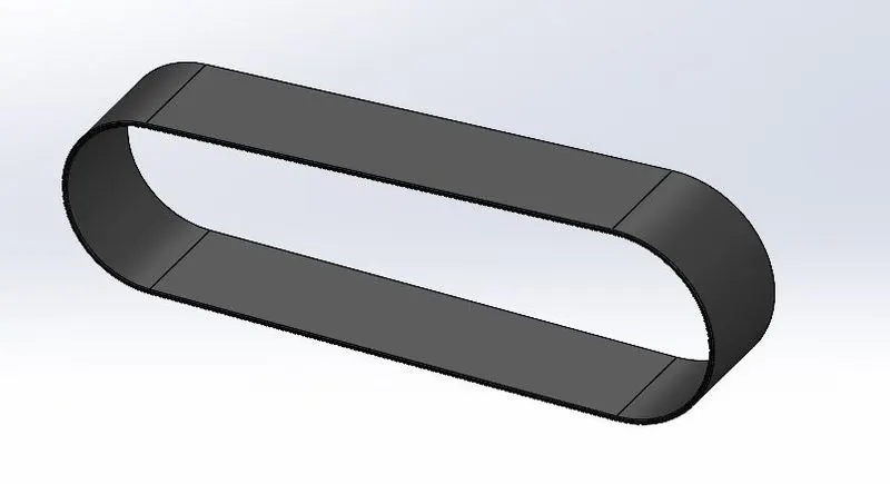
- Transmission Belt - It’s a rubbered vulcanised loop of flexible material in which the power is transmitted from driver shaft to driven shaft.
Features used – Boss extrude, fillet.
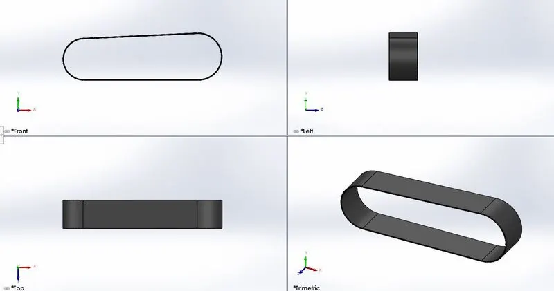
Various directional views of transmission belt,
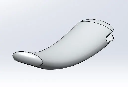
2. Kickstand – It’s a part in bike which helps in keeping the bike in upright position without leaning against object or with aid of person. Kickstand is connected to chassis and flips down and makes contact with ground.
Features used – Loft, boss extrude, cut extrude, split, dome, fillet.
Various directional views of kickstand,
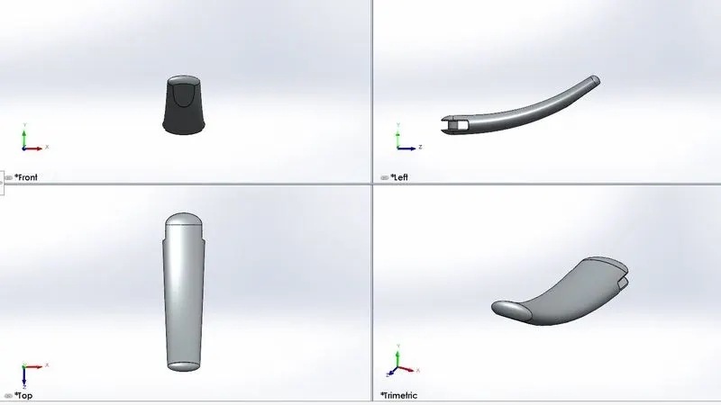
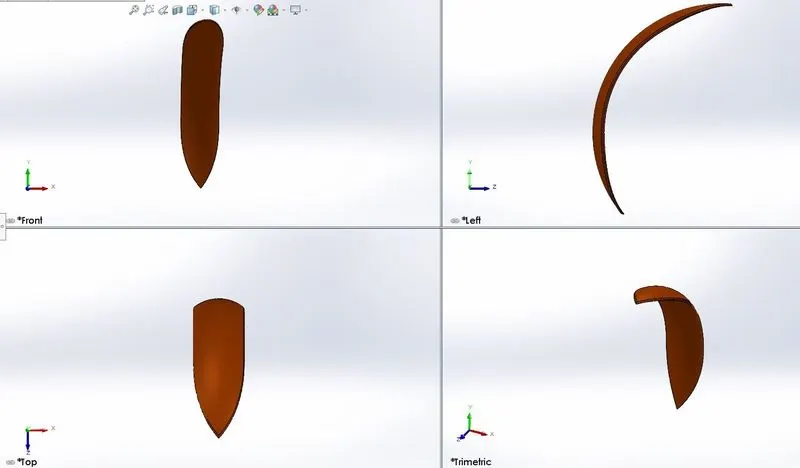
3. Front Fender – Its apart in bike that is attached concentric above the front tyre. Its purpose is to prevent sand, mud, fluids spluttering over the rider or other front bike body parts.
Features used – Revolve boss, split, fillet.
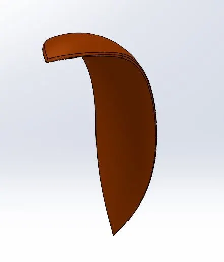
Various directional views of front fender,
4. Rear Fender – Its part in motorcycle that frames the upper part of rear wheel. It prevents spluttering of sand, dirt, mud over other rear vehicle riders.
Feature used - Revolved boss, split, shell, fillet.
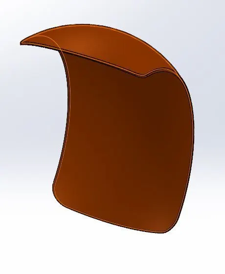
Various directional views of rear fender,
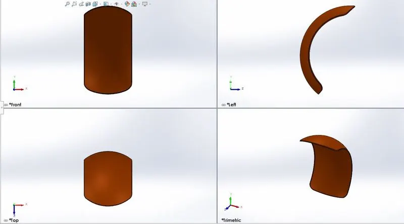
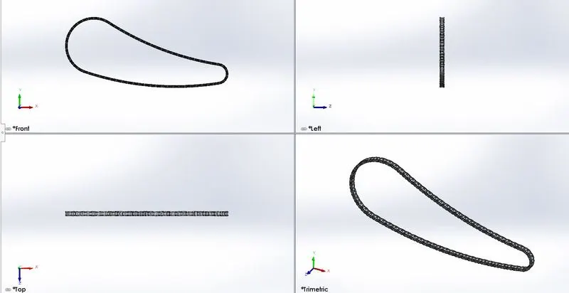
5. Chain – It’s a part in motorcycle which connects the engine to rear wheel sprocket part of the bike. Its used for providing mechanical power.
Features used – Projected curve, extruded boss, curved pattern, mirror, fillet.
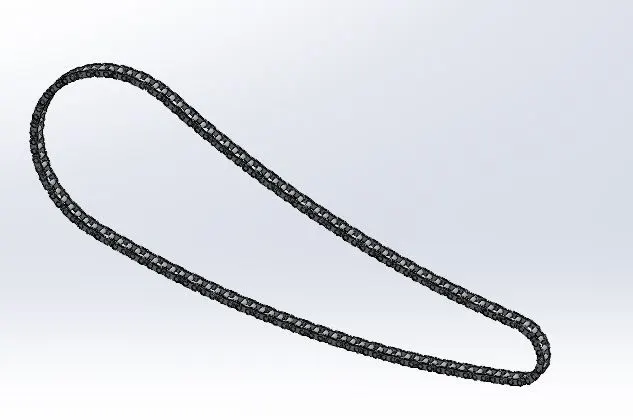
Various directional views of chain,
6. Oil Tank - It stores the oil for lubrication of engine parts to prevent wear and tear.
Features used – Extrude boss, shell, combine, fillet.
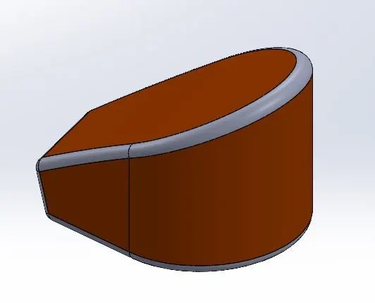
Various directional views of oil tank,
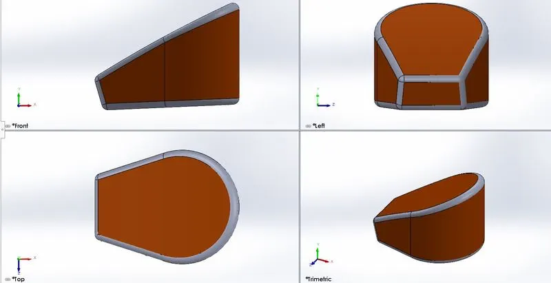
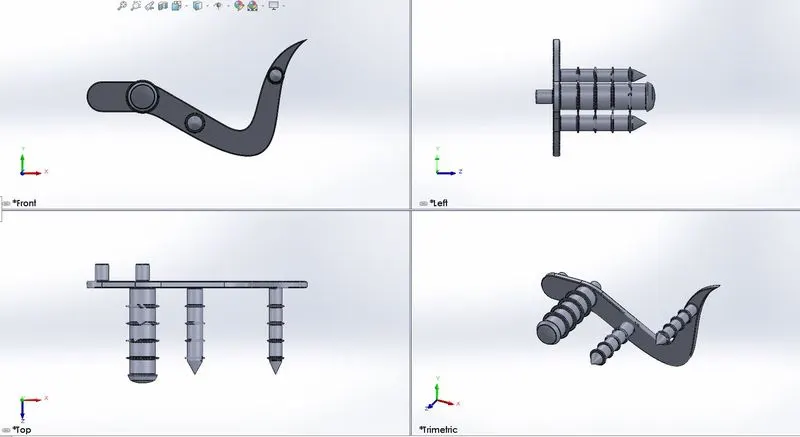
7. Pedals – Pedals are provided towards both side of the legs its function is to change the transmission speed as well as to apply brakes to rear wheel.
Features used – extruded boss, revolved boss, dome , chamfer, linear pattern, fillet.
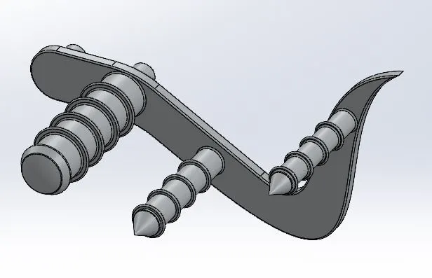
Various directional views of pedal,
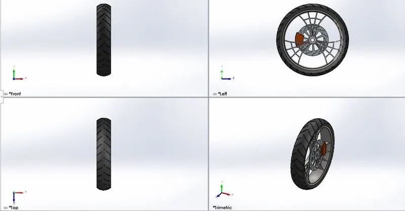
8. Front Wheel – It’s a circular part of metal where the centre is bored with a circular hole in which a axle with bearing passes and about which the wheel rotates.
Features used – Extrude boss, cut extrude, revolved cut, circular pattern, combine, fillet.
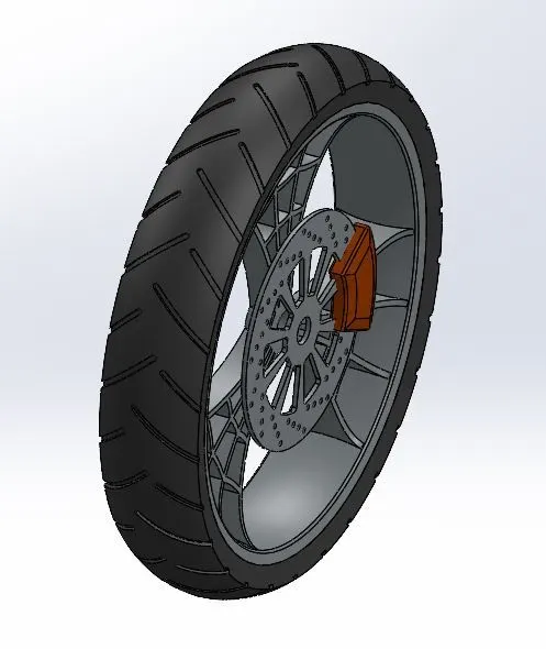
Various directional views of front wheel,
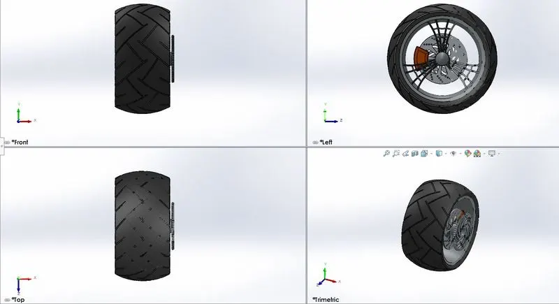
9. Rear Wheel - It’s a circular part of metal where the centre is bored with a circular hole in which a axle with bearing passes, with sprocket attached to it and about which the wheel rotates.
Features used – Extrude boss, cut extrude, revolved cut, circular pattern, combine, chamfer, fillet, chamfer.
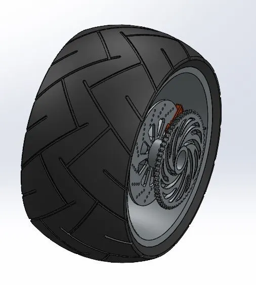
Various directional views of rear wheel,
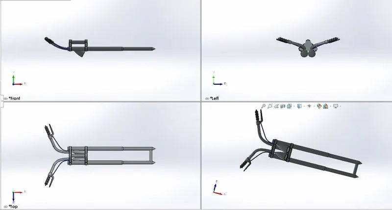
10. Front Fork – It’s the body part of motorcycle which holds the front wheel. It consists of 2 fork blades which are joined at top by a fork crown.
Features used -revolved boss, extrude boss, extrude cut, dome, revolve cut, swept boss, projected curve, mirror, combine, fillet.
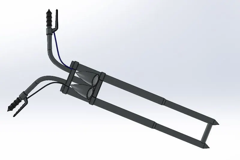
Various directional views of front fork,
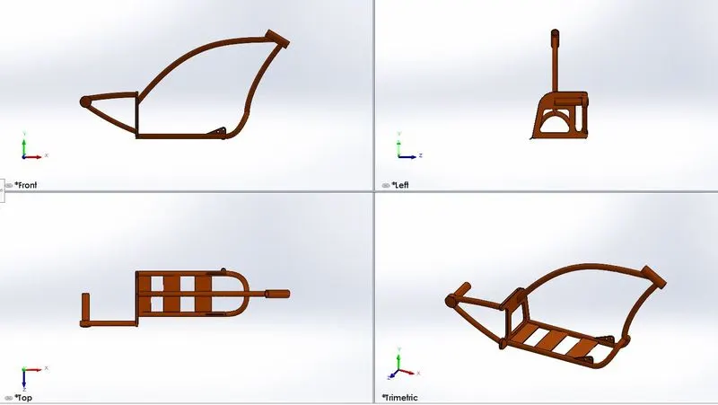
11. Chassis – It’s the main body part of a motorcycle which is a hollow tube structure which houses gearbox, engine, front fork, rear wheel, fuel tank.
Features used - Revolved boss, extruded boss, swept boss, projected curve, extruded cut, mirror, dome, combine, chamfer, split.
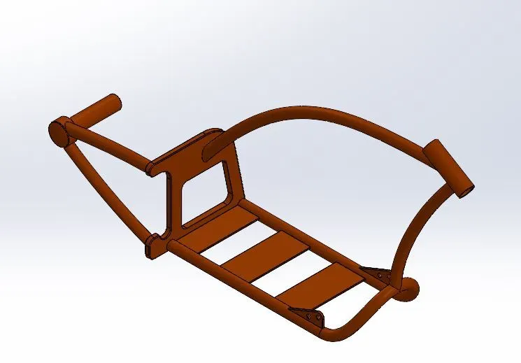
Various directional views of chassis,
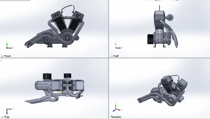
12. Engine – Is a machine which converts heat energy to mechanical work. When the fuel is ignited in it.
Features used – Extrude boss, swept boss, projected curve, extrude cut, revolve boss, linear pattern , circular pattern, compositive curve, mirror, chamfer, split.
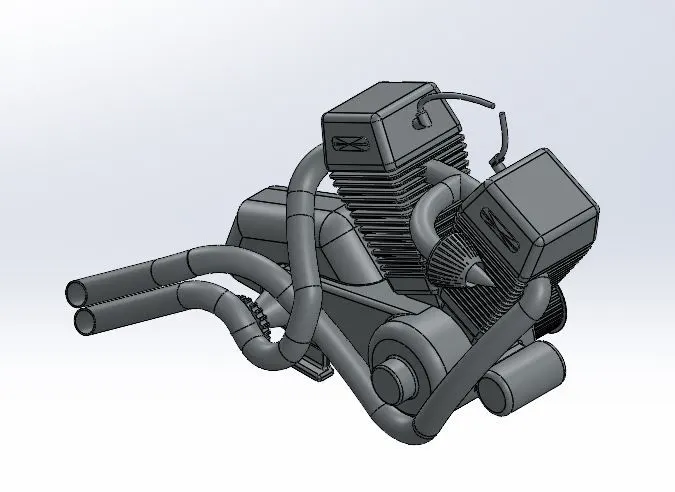
Various directional views of engine,
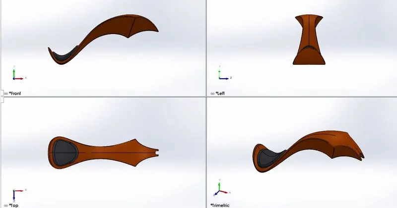
13. Gas Tank – Its mainly used in storage of fuel which rests in the top of chassis fuel tank tubes connected to engine.
Features used – Surface loft, projected curve, surface knit, swept surface, swept cut, split, mirror, fillet.
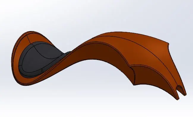
Various directional views of gas tank,
Assembly of American Chopper –
Term assembly is referred to placing different things / components together that create a complete product that performs the intended function. Firstly, chassis part is inserted into to the SolidWorks assembly environment, then engine, kickstand, oil tank, front fork, front wheel, rear wheel, pedal, fuel tank, front fender, rear fender are assembled by applying necessary mates.
Features used - Insert part, mates.
Insert part/component – Various different parts are added to SolidWorks environment to obtain a final product.
Mates – Mates create geometric relationship between parts in assembly.
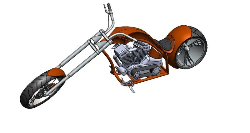
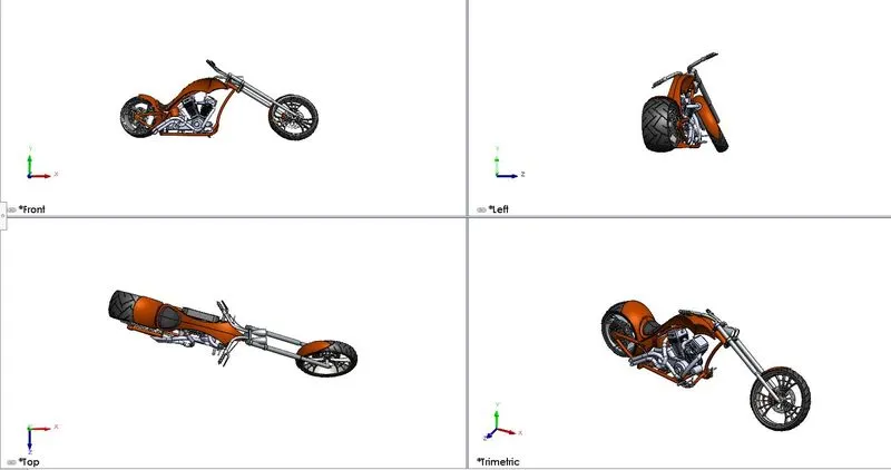
Various views of assembly of American chopper,
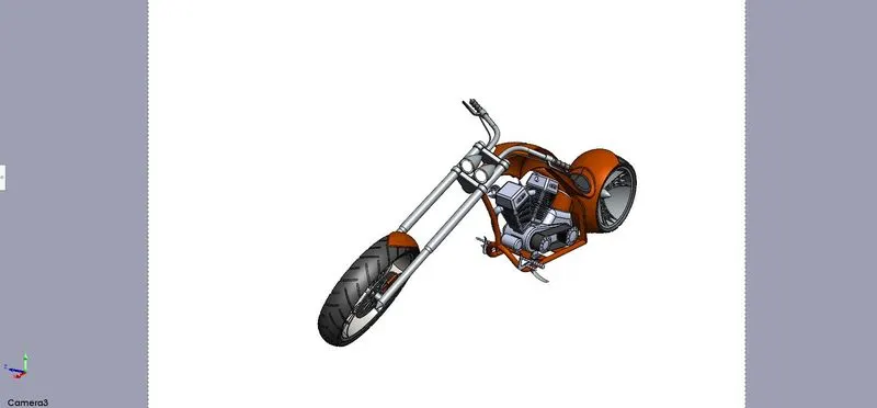
Camera setup view –
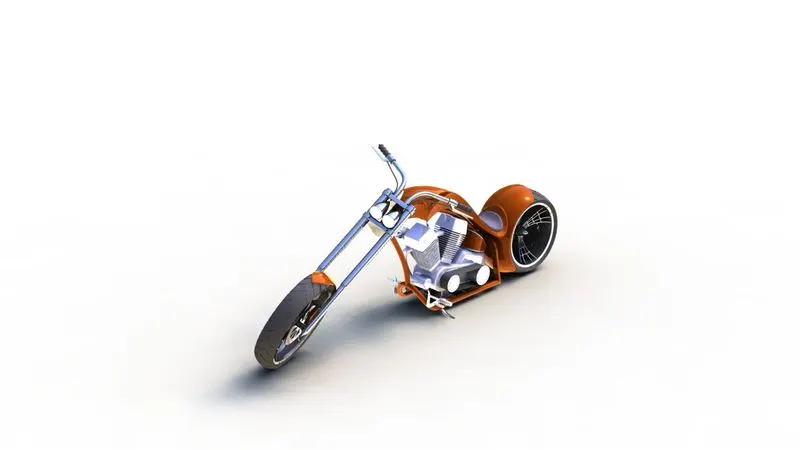
Rendering –
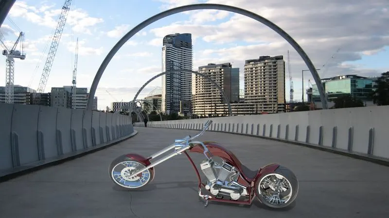
Rendering is the process of creating realistic images of photorealistic model with predefined environment/background.
Photo realistic rendering can be done in two ways,
- Photoview 360
- SolidWorks visualise
PhotoView 360 is a SOLIDWORKS add-in that produces photo-realistic renderings of SOLIDWORKS models. The rendered image incorporates the appearances, lighting, scene, and decals included with the model.
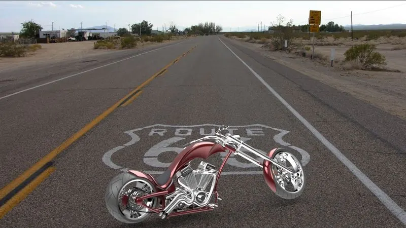
SolidWorks Visualise –
SolidWorks Visualize allows us to leverage our 3D CAD data to create photo-quality content in the fastest and easiest way we can–from images to animations, interactive web content, and immersive Virtual Reality. Bring our products to life.
In visualise its the actual view in the real environment we can see that how assembly of chopper really look in particular environment.
Conclusion –
- Individual parts of American chopper are modelled
- Part are inserted int assembly and assembled with applying mates between various parts.
- Rendering was done in photoview 360 and visualise of photorealistic image.
The link for the above parts and assembly of chopper is attached in below link,
https://drive.google.com/drive/folders/1buPAu1vSzoutfCXfY5UI7S281NcNn79a?usp=sharing