Why Meshing Matters in FEA and CFD: Element Types, Mesh Quality and Convergence
The mesh decides how accurate, how fast and how reliable a simulation is. We solved the same beam with three element types to show how much it matters, then cover element choice, quality checks, convergence studies and stress singularities.
 Skill-Lync·Updated 17 Oct 2026·10 min read
In short
- Meshing splits a CAD model into small elements (FEA) or cells (CFD) so the governing equations can be solved numerically. The mesh is where the "approximate" in "approximate solution" comes from.
- The mesh controls three things: accuracy (discretisation error), cost (degrees of freedom and run time) and robustness (badly shaped elements make solvers fail or mislead).
- Element type matters as much as element count. In our worked study, linear triangles at 400 degrees of freedom were 18% too stiff, while quadratic triangles at the same size were within 0.2%.
- Never trust a single mesh. Refine until the quantity you care about stops changing, and watch for stress singularities that never converge.
What is meshing?
Real parts have shapes, loads and materials for which the governing equations (elasticity for structures, Navier-Stokes for fluids, heat conduction for thermal problems) have no exact closed-form solution. Simulation gets around this by discretisation: the geometry is divided into many small, simple pieces, and inside each piece the unknown field (displacement, temperature, velocity) is approximated with a simple function. The pieces are called elements in FEA and cells in CFD. The points that connect them are nodes. The collection of all of them is the mesh.
Each node carries unknowns called degrees of freedom (DOF). A 3D solid node has three displacements; a shell node has three displacements and three rotations. The solver assembles one equation per DOF, so a model with 2 million nodes in 3D has roughly 6 million unknowns. That number drives memory, run time and licence cost.
If you are new to the method itself, start with our beginner's guide to FEA; this article assumes you know what a finite element model is and focuses on why the mesh matters so much.
Why meshing matters: accuracy, cost and robustness
1. Accuracy: the mesh is your discretisation error
Inside each element, the solution can only vary in the way its shape functions allow: linearly for a 3-node triangle or 4-node tetrahedron, quadratically for elements with midside nodes. Where the real field changes quickly (around a hole, a fillet, a contact patch, a boundary layer), too few or too simple elements cannot follow it. The result is usually a model that is too stiff: displacements too small and peak stresses too low, which is the unsafe direction for a strength check.
2. Cost: every extra element costs time
Refining a 3D mesh by half the element size multiplies the number of elements by about eight. Implicit solvers then need much more memory and time. In explicit dynamics (crash, drop tests) it is worse: the stable time step is proportional to the smallest element's size, so a handful of tiny elements can slow the whole run. Our article on implicit vs explicit FEA works through that example.
3. Robustness: bad elements break solvers
Highly distorted elements give inaccurate stiffness and stresses, and inverted elements (negative Jacobian) stop a solve outright. In CFD, highly skewed or non-orthogonal cells slow or prevent convergence. Much of a CAE engineer's day is spent fixing geometry and element quality so that the solver gets a fair problem.
A worked study: same beam, three element types
To show how much the mesh matters, we wrote a short plane-stress finite element program for this article and solved one simple problem many times: a steel cantilever, 100 mm long, 10 mm deep and 1 mm thick (E = 200 GPa, ν = 0.3), fixed at one end with a 100 N tip load. Beam theory gives a tip deflection of PL³/(3EI) = 2.000 mm, plus about 0.016 mm from shear, and a bending stress of 300 MPa at the top surface at mid-span. Our most refined model (21,120 DOF) gives 2.012 mm, within 0.2% of beam theory, and we use it as the converged reference.
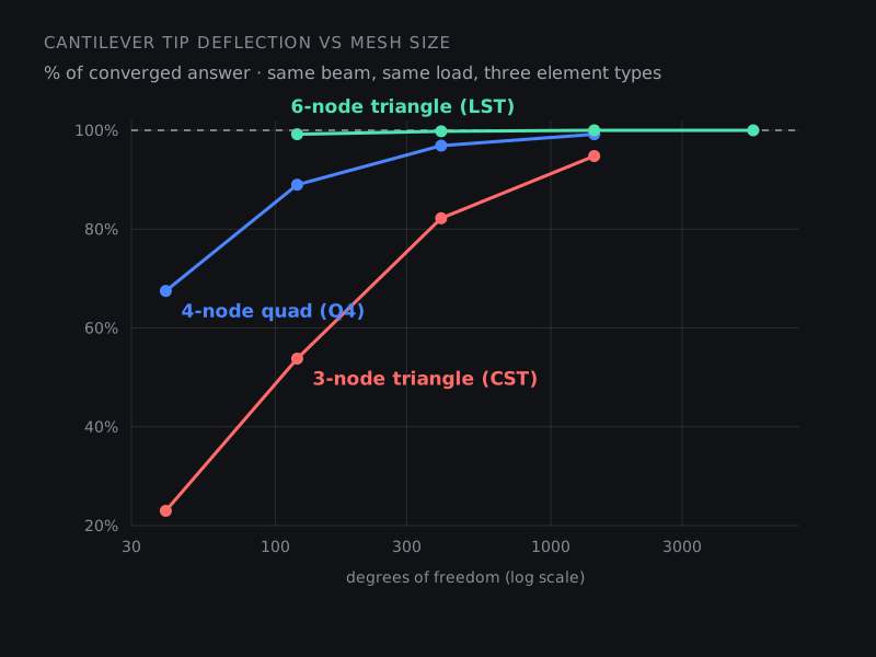
We then meshed the beam with three element types at increasing refinement: 3-node triangles (CST, constant strain), 4-node quads (Q4) and 6-node quadratic triangles (LST). "Mesh" is elements along the length × through the depth; deflection is shown as a percentage of the converged value, and stress is the top-surface value at mid-span.
| Element | Mesh | DOF | Deflection | Stress (MPa) |
|---|---|---|---|---|
| CST | 20 × 2 | 120 | 53.8% | 110 |
| Q4 | 20 × 2 | 120 | 89.0% | 281 |
| LST | 10 × 1 | 120 | 99.2% | 310 |
| CST | 40 × 4 | 400 | 82.2% | 209 |
| Q4 | 40 × 4 | 400 | 96.9% | 298 |
| LST | 20 × 2 | 400 | 99.8% | 303 |
| CST | 80 × 8 | 1,440 | 94.8% | 263 |
| Q4 | 80 × 8 | 1,440 | 99.2% | 301 |
| LST | 40 × 4 | 1,440 | 100.0% | 301 |
What this shows:
- Linear triangles are far too stiff in bending. A 3-node triangle has constant strain, so it cannot represent the strain gradient through the depth of a bent beam. Even with 8 elements through a 10 mm depth, the deflection is 5% low and the stress 12% low. The same weakness applies to 4-node tetrahedra in 3D, which is why most analysts default to 10-node tets for solids.
- Same DOF, very different answers. At 400 DOF the error ranges from 18% to 0.2% depending only on the element formulation. Counting elements is not enough; you need to know what your elements can represent.
- Stress converges more slowly than displacement. Stresses come from derivatives of displacement, so they carry larger errors. Always judge convergence on the result you will actually use, which is usually stress.
- A coarse mesh errs on the unsafe side. Every under-refined model above under-predicted the stress. A design that "passes" on a coarse mesh may fail on a converged one.
Commercial codes improve on these textbook elements (reduced integration, incompatible modes and other enhancements), but the lesson holds: element choice and refinement must be checked, not assumed. Classic benchmark sets such as MacNeal and Harder's standard problems for testing finite element accuracy exist precisely because element formulations behave so differently.
Element and cell types
| Type | Typical use | Watch out for |
|---|---|---|
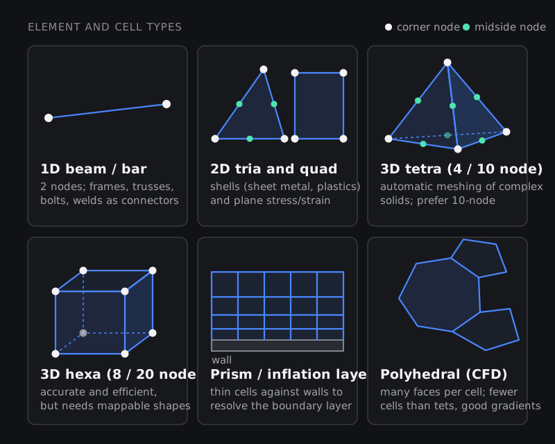
| 1D beam / bar / spring | Frames, trusses, stiffeners, bolts and spot welds as connectors | Correct section properties and offsets; no local stresses at joints |
| 2D shell (tria, quad) | Sheet metal, BIW, plastic covers, thin-walled castings, meshed on the mid-surface | Thickness assignment, mid-surface quality, too many triangles in bending regions |
| 3D tetrahedron (4 or 10 node) | Complex solid parts meshed automatically | 4-node tets are stiff; use 10-node or very fine meshes for stress |
| 3D hexahedron (8 or 20 node) | Bulky regular parts, rubber, crash and forming models | Needs geometry split into sweepable or mappable blocks |
| Prism / inflation layers (CFD) | Boundary layers on walls | First-layer height (y+), growth ratio, layer count |
| Polyhedral cells (CFD) | General-purpose internal and external flow meshes | Quality at interfaces with prism layers |
Linear elements are cheap per element; quadratic elements with midside nodes follow curved geometry and stress gradients far better. In structural work, use quadratic elements wherever stress matters unless you have a specific reason not to (for example explicit crash, which favours linear reduced-integration elements for speed and robustness).
Mesh quality checks
Pre-processors such as HyperMesh, ANSA and Ansys Meshing report quality metrics for every element. The names vary slightly between tools, and every company sets its own limits, but the common ones are:
| Metric | What it measures | Why it matters |
|---|---|---|
| Aspect ratio | Longest edge relative to shortest | Long, thin elements lose accuracy in the short direction |
| Skewness / minimum and maximum angles | How far angles are from the ideal (60° for triangles, 90° for quads) | Highly skewed elements give poor stresses; in CFD they hurt convergence |
| Warpage | How far a quad's four nodes are from a single plane | Warped shells behave badly in bending |
| Jacobian | Distortion of the element relative to its ideal shape; negative means inverted | Low or negative values give wrong stiffness or stop the solver |
| Orthogonality (CFD) | Alignment between the line joining cell centres and the shared face | Poor orthogonality adds numerical error to fluxes |
| Size transition / growth rate | How quickly element size changes between neighbours | Abrupt jumps create artificial stress or flow features |
Treat the thresholds in your company's meshing guideline as the rule for your models. More important than any single limit is where the poor elements are: one distorted element in a lightly loaded corner matters less than a slightly poor one at the fillet you are assessing.
How to run a mesh convergence study
- Pick the output that matters: peak stress at a fillet, deflection at a point, natural frequency, pressure drop. Convergence is judged on that number.
- Refine where it changes fast. Local refinement around the region of interest is more efficient than refining the whole model.
- Solve at least three meshes with a consistent refinement ratio (element size reduced by about 1.5 to 2 each time).
- Plot the output against element size or DOF. When the change between the last two meshes is small (many teams use a few percent), you are close to converged.
- Record it. A convergence plot is the evidence a reviewer will ask for. For CFD, the Grid Convergence Index described in NASA's guide to spatial convergence turns the study into an error estimate. In structural mechanics, ASME's V&V 10 standard frames this as part of solution verification.
Stress singularities: when refining makes it worse
Sometimes the peak stress keeps rising with every refinement and never settles. That is usually a singularity: a point where the idealised model has infinite stress in theory. Typical causes are sharp re-entrant corners with zero radius, point loads or point constraints, and edges where a rigid fixed boundary meets a loaded part.
Singularities are features of the model, not the part. The fixes are to model the real fillet radius, spread loads and constraints over realistic areas, or read stresses away from the singular point (by Saint-Venant's principle the far field is unaffected). If you see stress growing without limit in a convergence study, do not report the peak; find out why it is growing.
Meshing for CFD vs FEA
The ideas are the same but the priorities differ:
- Boundary layers: CFD needs thin prism layers on walls sized for a target y+ value. Our guide to CFD works out the first-cell height for a car at 100 km/h.
- The fluid volume: CFD meshes the space the fluid occupies, which often has to be extracted or wrapped from the CAD, not the solid part itself.
- Size: industrial CFD meshes routinely run to tens of millions of cells; many structural models are smaller but have far more parts, connections and contacts.
- Connections: structural models spend much of their meshing time on welds, bolts, adhesives and contacts, which are often modelled with 1D elements and special connector definitions.
A meshing checklist before you solve
- Geometry is clean: no gaps, slivers, duplicate surfaces or tiny features that do not affect the result.
- Element type suits the physics (shells for thin walls, quadratic solids for stress, prism layers for walls in CFD).
- Mesh is finer where gradients are steep and transitions smoothly to coarser regions.
- Quality checks pass company limits, especially in the regions you will report.
- Connections and contacts are meshed consistently on both sides.
- A convergence study backs the number you report.
How to get good at meshing
Meshing is the skill CAE employers test first, because it is where most of an analyst's time goes and where most errors start. Learn one industrial pre-processor properly, practise on real parts, and always pair meshing with convergence checks. For structured practice, see HyperMesh for FEA Plastic and Sheet Metal Applications, Preprocessor for Structural Analysis using ANSA, Advanced CFD Meshing using ANSA, or the PG Program in Automation and Pre-Processing for FEA and CFD. Our technical blogs also cover specific techniques, such as tetra meshing and mid-surface meshing in HyperMesh.
Frequently asked questions
Does a finer mesh always give a more accurate result?
For smooth problems, refining reduces discretisation error, but with diminishing returns and rising cost. At singular points, refinement makes the peak stress grow without limit, so "finer" does not mean "more correct" there.
What is a good mesh size?
There is no universal number. A practical start is a few elements across the smallest feature that matters (for example, several elements around a fillet you are assessing) and then a convergence study to confirm it.
Tetra or hexa mesh?
Hexahedra give more accuracy per DOF and are preferred where the geometry allows them. Tetrahedra mesh any shape automatically; with 10-node elements and enough refinement they are accurate for stress. Many industrial models mix both.
Why are linear triangles and tetrahedra called "stiff"?
They can only represent constant strain inside each element, so they cannot follow the strain gradient in bending. The model resists deformation more than the real part, giving smaller displacements and stresses unless the mesh is very fine.
How do I know my mesh is converged?
Solve at least three systematically refined meshes and check that the quantity you care about changes by only a small amount between the last two. If a peak stress keeps climbing, investigate a singularity.
Which meshing tool should I learn?
HyperMesh and ANSA are widely used in automotive CAE; Ansys Meshing, Abaqus/CAE and Simcenter tools are common elsewhere. The principles carry over, so learn one deeply.
Sources and further reading
- R. H. MacNeal and R. L. Harder, A proposed standard set of problems to test finite element accuracy, Finite Elements in Analysis and Design 1 (1985) 3–20
- ASME, V&V 10: Standard for Verification and Validation in Computational Solid Mechanics
- NASA Glenn Research Center, Examining Spatial (Grid) Convergence
- Worked study: plane-stress cantilever solved by Skill-Lync with CST, Q4 and 6-node triangle elements (fully integrated, averaged nodal stresses); beam-theory reference values computed from PL³/3EI and Mc/I