Menu


Modified on
The Basics of Mold Design 4 (Part 3): Discussing Drafts, Shrinkage, and Inserts

Skill-Lync
We are about to conclude our series on the basics of mold design. The following aspects will be discussed in detail:
- Matching drafts
- Shrinkage
- Inserts
Matching Drafts
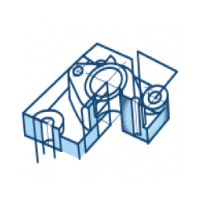
The concept of matching drafts can be explained better by using two models, as you can see in the image below. The difference is that the first model has a 90-degree cut in the groove, whereas, in the second one, there is a small inclination.

In the case where there is a 90-degree cut groove when the core block tries to move in the downward direction after the plastic material is solidified, the core steel block will rub against the steel cavity block.
The core and cavity blocks will get damaged if the process is repeated many times. When the mold blocks are damaged, the plastic material will seep through the blocks and result in flashes.
However, in the case where the cut is inclined, there will not be any rubbing of the mold blocks. When the mold blocks move relative to each other, they immediately get separated. This concept is similar to the drafts used in plastic parts, but here the drafts are for the mold blocks and not for the parts themselves.
The core, the cavity, and their assembled version for this model are shown in the image below.

The rubbing of the mold blocks does not occur in all cases. However, in cases where they do occur, you should have at least seven degrees of inclination so that the steel blocks do not rub against each other.
If you get a part with a 90-degree cut like that of the first case, you should notice a side groove in the model. If you try to make a mold for this component, the mold blocks will get damaged over time.
Therefore, as a mold designer, you are supposed to tell the product design team or the customer that there are no adequate matching drafts in the given model, and a revision of design is required. You may also suggest that an inclination of seven degrees can be added.
In one of the previous parts, you read that the component's profile is not followed throughout the mold block to ensure easier machining. Similarly, in this case, the groove profile will not be followed throughout the mold block.
The groove profile will follow the component's shape to a certain distance (usually 25 to 30 mm), and then it is made as a flat parting surface. Even in this case, relief is provided to avoid damage to the mold blocks.
Shrinkage
Assume that you are given a model with all the dimensions, as shown below.

Now, you are assigned the task of creating a mold for the component.
Suppose you create mold blocks for the same dimensions, as shown in the image. In that case, the component will shrink once the molten plastic feed material solidifies, and the final part you obtain will be even lesser in size compared to what you see in the diagram.
To avoid this problem, you should always create a mold that is larger than what is desired. The exact increment in size for the appropriate mold design will depend on the material properties. As a mold designer, you will be informed about the material to be injected and its shrinkage value.

Shrinkage value is a material property and is always fixed depending on the material.
For example, the product design team mentions that the plastic material for the component has a shrinkage value of 0.5%. Therefore, to account for the shrinkage of the component, you will have to create a mold that is 0.5% bigger than the desired component.
Core Cavity Inserts
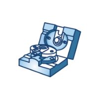
In the left diagram (shown below), you have a typical core and cavity. Interestingly, the entire core and cavity block are formed using a single material. When the profiles are cut in a single, large block, it is known as an integral core and cavity block.
In the second case (right-hand side in the image below), two blocks are used on the core side, and two on the cavity side. There are smaller red and green colored blocks with the part's profile, and then there are large grey boxes around them.

So, in the second case, the core and the cavity blocks are not made up of a single integral block. The grey part is a separate block, and the red block is inserted into the gray block so that the two blocks function together as the complete core block.
As far as the core and the cavity functionality is considered, both the integral and the core cavity insert mold blocks produce the same result. However, as you keep creating newer plastic components in the mold, the block may get damaged or worn out over time.
As a result, only the inserts are replaced rather than the entire block in this case. This technique lowers the overall cost of injection molding. In actual practice, the inserts are made using high-grade steel. The other blocks are made of lower-grade steel to further reduce the cost of the mold.
The inserts are used only in the final molds, which are used in the actual production process. Designing the mold for the first time is only for prototypes, and high-grade steel is not used anywhere for initial designs and prototypes.
Conclusion
With this, we conclude the fourth week of the ongoing series on the basics of mold design. But it doesn't end here!
As is the case with any topic, learning about mold design fundamentals is necessary if you want to pursue a career in this domain. You can get into more detail about injection molding with Skill-Lync's online courses. Click here to learn more.
Author

Navin Baskar
Author
Skill-Lync
Subscribe to Our Free Newsletter

Continue Reading
Related Blogs
Explore the fundamentals of vehicle dynamics and ultimate trends in the field from design and modeling to control with Skill Lync's exclusive course on the subject. Read about how Skill-Lync's CAE courses can help you get employed.
28 Jul 2020
In this article, we will briefly discuss the working, applications, and features of the one-dimensional systematic simulation tool, GT-Power, in Emission Control Strategy, engine calibration, hybrid vehicle modeling. Read about how Skill-Lync's CAE courses can help you get employed.
28 Jul 2020
This article offers a brief introduction to the globally accepted standard of Geometric Dimensioning and Tolerancing, and its importance for the entire manufacturing process. Read about how Skill-Lync's CAE courses can help you get employed.
28 Jul 2020
In this blog we will read about Going a step into Biomechanics and how Skill-Lync's CAE course will help you get employed.
09 May 2020
The powertrain is the most prominent source of vibrations that affects the driving experience for the people on board. This blog from Skill-Lync examines these vibrations to help enhance that experience.
21 Aug 2020
Author
Skill-Lync
Subscribe to Our Free Newsletter
Continue Reading
Related Blogs
Explore the fundamentals of vehicle dynamics and ultimate trends in the field from design and modeling to control with Skill Lync's exclusive course on the subject. Read about how Skill-Lync's CAE courses can help you get employed.
28 Jul 2020
In this article, we will briefly discuss the working, applications, and features of the one-dimensional systematic simulation tool, GT-Power, in Emission Control Strategy, engine calibration, hybrid vehicle modeling. Read about how Skill-Lync's CAE courses can help you get employed.
28 Jul 2020
This article offers a brief introduction to the globally accepted standard of Geometric Dimensioning and Tolerancing, and its importance for the entire manufacturing process. Read about how Skill-Lync's CAE courses can help you get employed.
28 Jul 2020
In this blog we will read about Going a step into Biomechanics and how Skill-Lync's CAE course will help you get employed.
09 May 2020
The powertrain is the most prominent source of vibrations that affects the driving experience for the people on board. This blog from Skill-Lync examines these vibrations to help enhance that experience.
21 Aug 2020
Related Courses