
DussehraFestive scholarship on Skill-Lync courses, this week onlyFestive scholarship is openOffer ends Wed, 21 Oct, 11:59 pm IST.
Dussehra 2026

Start your next chapter this Dussehra

Tell us where you want to work. A counsellor will match you to the right course and confirm the festive scholarship you qualify for.

  • Festive scholarship on course fees, confirmed on your call
  • Free 20-minute call to map the right course to your goal
  • Real industry projects and placement support with every course

Offer ends Wed, 21 Oct, 11:59 pm IST

3,905 engineers placed since 2019 · 1,277 hiring companies

By submitting you agree to our Terms and Privacy Policy.

You're on the list

Browse courses
Mechanical · PG program

Post Graduate Program inSolidworks Design and Analysis

A 6-month long intensive program comprising 5 courses that train you on all the essential engineering concepts and tools that are essential to get into top OEMs as a Design Engineer.

Duration
24 weeks
Content
35 hours
Courses
4
Projects
8
Mode
Online
Overview

What you'll
be able to do.

  • This course helps you understand the design tools and essential concepts of SolidWorks.
  • Students will gain knowledge of engineering concepts and be able to understand different concepts such as solid modelling, surface modelling, and assembly.
  • After the completion of the program, they will be able to perform FEA and CFD analysis in SolidWorks.
  • They will also gain knowledge in Multi-body dynamics.

Why this program

  • Ability to design your own products while also being able to optimize your products.
  • Hands-on experience in simulation of your designed products using static and dynamic tools.
  • The student can be employed as
    • Design Engineer
    • Product Design Engineer
    • Design and Release Engineer (D&R)
Tools you'll use
SOLIDWORKS
Curriculum

4 courses,
26 modules.

Get the full syllabus ↓
  1. 01Surface Modelling of an Aston Martin Car using SolidWorks5 modules
    1. Introduction to SolidWorks Surface Modelling InterfaceW01
      • Sketching tools
      • Surface modeling tools
      • Types of tools to create the surfaces
      • Blueprint setups
    2. Curve Generation in SolidWorksW02
      • Splines
      • Spline vectors
      • Equal curvature for splines
      • Constraining the splines
      • Creating a projected curve
      • Composite Curve Generation
    3. Surface generation Using Curves and SketchesW03
      • Types of surfaces
      • Boundary surfaces
      • Lofted surfaces
      • Filled surfaces
      • Ruled surfaces
      • Reference planes
      • Surface trims
      • Surface knit
      • Move/copy surfaces
      • Mirror surfaces
    4. Application of Solid ModellingW04
      • Revolve boss
      • Extrude cut
      • Linear and circular patterns
      • Fillets
      • Chamfers
      • Split Bodies
      • Creation of wheels
    5. Introduction to Assembly ModuleW05
      • Inserting the parts
      • Mates in assembly
      • Sub-assembly creations
      • The distinction between float and fixed parts
      • Importing sub-assemblies into other assemblies
      • Application of Decals
      • Appearance adjustment
  2. 02FEA using SOLIDWORKS10 modules
    1. Introduction to FEA W01
      • What is FEA?
      • Different types of Analysis Methods
        1. Analytical Method
        2. Experimental Method
        3. Numerical Method
      • FEA explanation with cantilever beam
      • Stress-Strain plot
      • General steps followed in FEA
      • Mesh elements
        1. H-refinement
        2. P-refinement
      • Summary
    2. Introduction to Types of FEA analysisW02
      • Structural Analysis
      • Static Analysis
      • Dynamic Analysis
      • Difference between Static and Dynamic Analysis
      • Linear and Nonlinear Analysis
    3. Introduction to SOLIDWORKS Simulation EnvironmentW03
      • Important SOLIDWORKS modelling features
        • SOLIDWORKS Sketch
        • SOLIDWORKS Features
      • Introduction to SOLIDWORKS Simulation
      • Performing a Simple Cantilever Load Analysis
    4. Performing Basic FEA Analysis using SOLIDWORKS SimulationW04
      • Static Linear Analysis
      • Static Nonlinear Analysis
      • Dynamic Linear and Nonlinear Analysis
    5. 1D/2D and 3D FEA AnalysisW05
      • Situations where 1D, 2D and 3D simulations are used
      • Performing 1D simulation in SOLIDWORKS
      • Performing 2D simulation in SOLIDWORKS
      • Performing 3D simulation in SOLIDWORKS
    6. Parametric/Design StudyW06
      • What is a parametric study and why is it used?
      • Advantages of performing a parametric study
      • How to access parametric study in SOLIDWORKS?
      • Performing a parametric study on a wine bottle
    7. Buckling AnalysisW07
      • What is buckling?
      • Difference between bending and buckling
      • Relationship between buckling shape and types of fixtures
      • Performing a buckling analysis in SOLIDWORKS
    8. Fatigue AnalysisW08
      • What is a Fatigue Analysis?
      • Applications of Fatigue Analysis
      • Application of SN Curve in Fatigue Analysis
      • Endurance Limit
      • Stress Analysis of S-hook
      • Fatigue Analysis of S-hook
        • Constant Amplitude Fatigue Study
        • Variable Amplitude Fatigue Study
        • Harmonic (Fatigue of Sinusoidal Loading)
        • Random Vibration (Fatigue of Random Vibration)
    9. Drop TestW09
      • What is a drop test?
      • How do you access drop tests in SOLIDWORKS?
      • Performing a drop test of a PCB board
      • Discussion of results
    10. Frequency AnalysisW10
      • Reason for Performing a Frequency Analysis
      • Natural Frequency and Resonance
      • Mode Shapes
        Types of Solvers in SOLIDWORKS Frequency Analysis
      • Frequency Analysis of Support Brackets
      • Discussion of Results
  3. 03Flow Simulation using SolidWorks6 modules
    1. Introduction to CFD and SOLIDWORKS Flow SimulationW01
      • An Introduction to the Concepts of Computational Fluid Dynamics (CFD)
    2. Steady-state Simulation of a Pipe FlowW02
      • You will learn to model simple geometry using SOLIDWORKS.
      • You will also learn how to set up a fluid study in SOLIDWORKS, and understand the necessary boundary conditions, along with the initial conditions to run the simulation.
      • In this module, you will learn how to change the mesh settings as well.
      • Also, the following topics are covered in this week,
        • Simulating flow through a pipe.
        • Parametric studies and grid dependency tests.
        • Concepts of global maxima and global minima.
    3. Transient Flow Simulation of Flow over a CylinderW03
      • You will be introduced to the concepts of external simulation and transient analysis. You will be learning how to calculate the total flow time and output time step.
    4. Flow Over an AirfoilW04
      • You will learn how to import the NACA airfoil data into SOLIDWORKS to create airfoil geometry.
      • You will also learn how to
        • Simulate the flow over a 2D NACA airfoil.
        • Calculate the drag and lift forces for the various angles of attack.
    5. Flow over an IC Engine ValveW05
      • You will be learning the effect of the valve lifts over the mass flow rate. You will learn how to create flow trajectories.
      • And perform the following calculations,
        • Perform transient analysis at different valve lifts
        • Create a plot of lift vs mass flow rate
    6. Flow-through a Simple Centrifugal PumpW06
      • In this module, you will be introduced to the concept of a moving reference frame while also learning about the rotating body feature in SOLIDWORKS.
      • You will complete the following projects within this module:
        • Using the MRF approach to simulate flow through a centrifugal pump
        • Plotting a pump performance curve
  4. 04Multibody Dynamics using SolidWorks5 modules
    1. Design and MBD simulation on Geneva MechanismW01
      • The students will be introduced to
        • Motion study in SOLIDWORKS.
        • The concepts of the Geneva mechanism and its types.
        • How to model and assemble the external Geneva mechanism, and how to perform a motion study on it.
        • How to plot the contact force between the parts.
      • In this module, the students will understand,
        • The basics of modeling and assembling in SOLIDWORKS
        • Pre-processing the model for the motion analysis and running a simulation
        • Post-processing the simulation to get the results as plots
    2. Design and MBD Simulation on a Machine ViceW02
      • The students will be introduced to the machine vice and will learn to model and assemble the machine vice.
      • The students will learn about screw mates and how to perform motion studies on them.
      • These are the things you will learn in this module,
        • Introduction to the screw mate
        • Tracing the displacement of the movable jaw
    3. Design and MBD Simulation on Planetary Gear TrainW03
      • The students will learn the concepts of the planetary gear train and gear terminology.
      • The students will learn how to import the standards gears in SOLIDWORKS to do the motion study.
      • These are the topics that be covered in this module,
        • Learning the basic gear terminology to model a gear
        • Understanding the speed and torque variation
        • Learning about the application of gear mate
    4. Design and MBD simulation on IC engine Piston AssemblyW04
      • The students will learn about the concepts of the IC engine piston kinematics and you will learn how to design and do the motion study.
      • The students will study the following in this module,
        • The effect of wrist pin offset in the piston displacement.
        • Assigning the material to the parts
    5. Design and MBD simulation on IC Engine Valve TrainW05
      • The students will learn to model the IC engine valve train.
      • The students will learn
        • The effect of spring in the valve train
        • How to calculate the cam lift
        • How to design the cam
      • These are the topics the students will study in this module,
        • Understanding the application of the CAM.
        • Calculate to model the CAM as per the valve lift specifications.
        • The damping coefficient and the free length of spring.
Industry projects

8 projects
you'll ship.

Our projects are designed by experts in the industry to reflect industry standards. By working through our projects, Learners will gain a practical understanding of what they will take on at a larger-scale in the industry. In total, there are 8 Projects that are available in this program.

Aston Martin Car design
Surface Modelling of an Aston Martin Car using SolidWorks

Aston Martin Car design

In this project, the students will be asked to surface model the Aston Martin car using Solidworks as software.
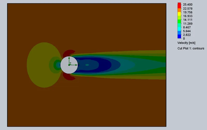
 Transient flow simulation of flow over a cylinder
Flow Simulation using SolidWorks

Transient flow simulation of flow over a cylinder

In this project, students will be asked to simulate a transient flow over a cylinder. They will employ external flow simulation techniques and analyze the results.
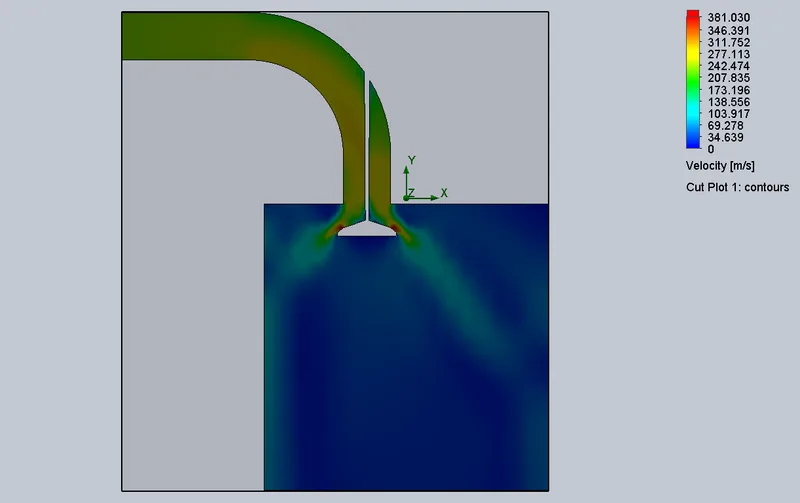
 Modeling and simulation of flow through flow-bench
Flow Simulation using SolidWorks

Modeling and simulation of flow through flow-bench

In this project, the students will study the valve flow for various valve lifts. They will run simulations and analyze the flow parameters.
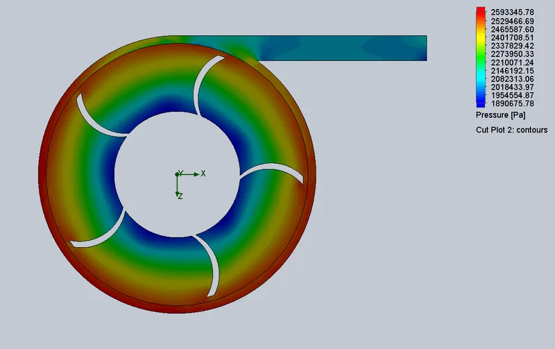
Design and analysis of centrifugal pump
Flow Simulation using SolidWorks

Design and analysis of centrifugal pump

In this project, students will simulate the flow of water inside a centrifugal pump. They will be asked to analyze the flow and compare the relationship between pressure ratio and …
Design and MBD Simulation on IC Engine Valve Train
Multibody Dynamics using SolidWorks

Design and MBD Simulation on IC Engine Valve Train

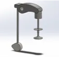
In this project, the student will model IC engine valve trains and assemble them. They will also calculate the cam lift required and design the cam to achieve the same.
Design and MBD simulation of Shaper Machine
Multibody Dynamics using SolidWorks

Design and MBD simulation of Shaper Machine

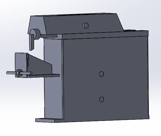
This project is about analyzing the motion and design optimization of a shaper machine. Here, the students will design the components of the shaper machine and optimize them to ach…
Design and MBD simulation of Pumpjack
Multibody Dynamics using SolidWorks

Design and MBD simulation of Pumpjack

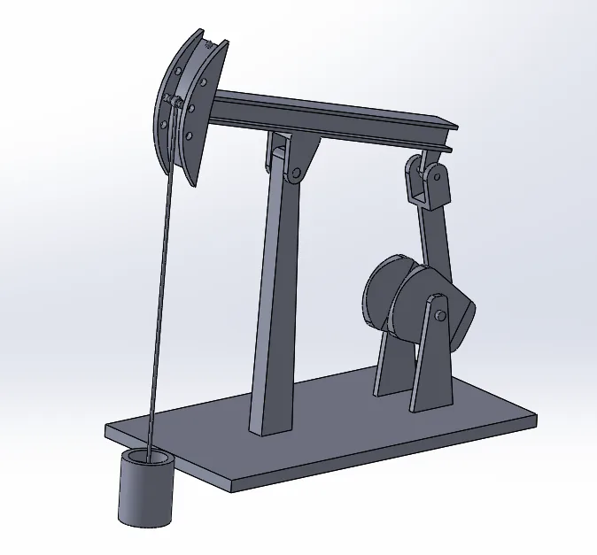
In this project, the students will design all the parts of a pumpjack and assemble them. They will simulate the same for extracting the displacement data.
Buckling Analysis
FEA using SOLIDWORKS

Buckling Analysis

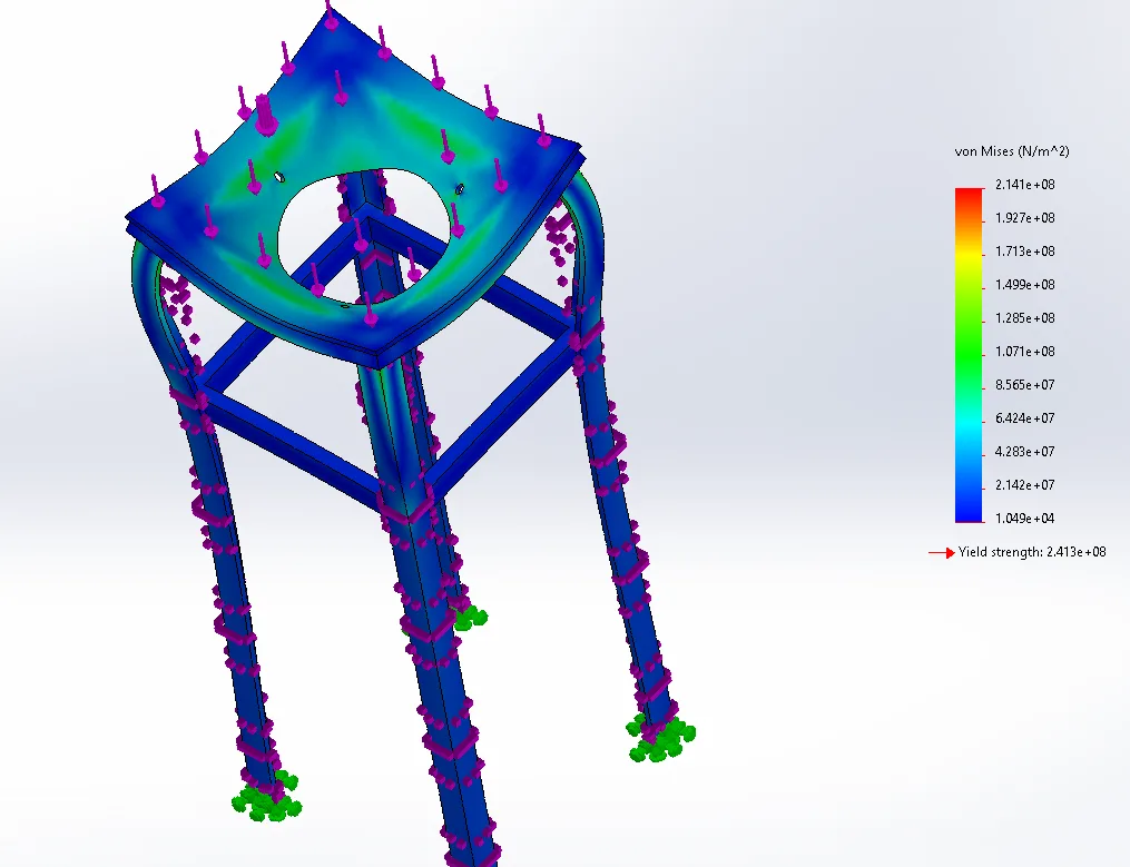
In this project, the students will be asked to perform buckling analysis on a cyclonic separator table.

Placements

7 learners placed
from this program.

Companies
5
Median CTC
4.2 LPA
20232.9 LPA
Sundaram Auto Components
Engineer

Dhanasekaran A
20222 LPA
Novatek
Design Engineer

Suresh K.
20227.45 LPA
Flowserve
Design Engineer

Ragunath Kandasami Sankari
20227.45 LPA
Flowserve
Design Engineer

Ragunath Kandasami Sankari
20224.2 LPA
Cyient
Design Engineer

Kundeti Ganesh
20224.2 LPA
CYIENT
GET

Kundeti Ganesh
Fee

One fee.
Everything included.

Become job ready with our comprehensive industry focused curriculum for freshers & early career professionals

Premium
₹2,75,000
Inclusive of all chargesEMI from ₹14,375/month
  • Career Service Assurance
  • Personalized Career Services Mentorship
  • 1 Year Access
  • Personalized Page
  • Live Individual & Group Sessions
  • Personalized & Hands-On
  • Job-Oriented Industry Relevant Curriculum
Check eligibility →
FAQ

Questions,
answered.

Who can take up SolidWorks courses?

Students and graduates of mechanical engineering and related streams of engineering can take up this Post Graduate Program in Solidworks Design and Analysis. If you are interested in designing and developing 3D models, you can pursue this SolidWorks online course.

Is this SolidWorks certification course an online program?

Yes, Post Graduate Program in Solidworks Design and Analysis is a 100% online course.

What is the duration of this Post Graduate Program in Solidworks Design and Analysis?

This SolidWorks online course is a 6-month program covering all the basic to advanced level concepts in SolidWorks.

What is the fee for this SolidWorks online course with the certificate?

The fee structure is flexible, and you can choose a plan that suits you. The basic plan would give you nine months of access, the pro plan would give you eighteen months of access, and the premium plan would provide you with lifetime access.

How much can a CAD Design Engineer earn?

According to AmbitionBox, the average salary of a CAD Design Engineer is ₹ 3 Lakhs per annum. However, it increases with your experience and expertise.

Is there any certificate for completing this SolidWorks online course?

Yes, After completing this Post Graduate Program in Solidworks Design and Analysis, you shall be given a course completion certificate. The top 5% of the scorers will be given a merit certificate alongside the course completion certificate.

Is there any technical support for this SolidWorks online course with the certificate?

Yes, you can clear your queries with the group and individual video support. Also, you can clear your queries with email and forum support.

Next step

Not sure it's
the right fit?

A counsellor will walk you through the syllabus, projects and fee options — and tell you honestly if another course suits you better.

Get the syllabus + a call back

We'll email the full syllabus and call within one working day.

By submitting you agree to our Terms and Privacy Policy.

Call usEnquire

Talk to a career counsellor

Free 20-minute call. We'll map the right course to where you want to work.

By submitting you agree to our Terms and Privacy Policy.