Nomenclature of airfoil model
Learn about airfoil design: understand airfoil nomenclature, parameters like camber, chord, and thickness, plus NACA’s four- and five-digit classification for airfoil profiles used in aerodynamic applications.
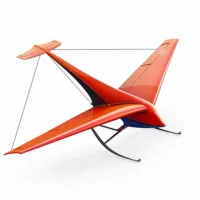
Airfoil:
It is the profile of the cross-section of an aerodynamic element (eg: the wing of an airplane). Due to this airfoil, the aerodynamic element is offered with lift force as well as a drag force. Out of all the possible profiles, only the airfoil profile can be offered by the least drag force.
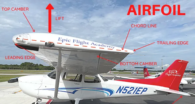
Airfoil nomenclature:
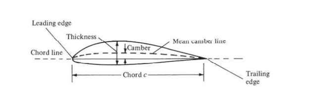
There are some modeling parameters in the airfoil model. They are the Mean camber line, Chord line, Camber, and thickness.
1. Mean camber line
The mean camber line is the locus of midpoints of the lines perpendicular to the line joining the leading edge and the trailing edge (chord line). It divides the airfoil symmetrically.
2. Chord line
The leading and trailing edges of the mean camber line are the most forward and rearward points. The straight line connecting the leading and trailing edges is the chord line.
3. Camber
The camber is the maximum distance between the mean camber line and the chord line, measured perpendicular to the chord line.
4. Thickness
The thickness is the distance between the upper and lower surfaces, also measured perpendicular to the chord line.
5. Leading edge radius.
The shape of the airfoil at the leading edge is usually circular and the radius of the circular curve is the leading edge radius. The leading edge radius is approximately 0.02c. Where ‘c’ is Chord length.
NACA (National Advisory Committee for Aeronautics) is an organization that developed the various airfoils and gave systematic names. For example NACA 2412.
The NACA followed a logical numbering system to distinguish the airfoils according to their properties. For example, the first family of NACA airfoils, developed in the 1930s, was the “four-digit” series, such as the NACA 2412 airfoil.
Here, the first digit (2) defines the maximum camber of the airfoil, and the second digit (4) defines the location of the maximum camber along the chord from the leading edge. The last two digits (12) define the maximum thickness of the airfoil.
For the NACA 2412 airfoil,
The maximum camber = 2*(c/100)
Located of the maximum camber = 4*(c/10).
The maximum thickness T= 12*(c/100).
Where ‘c’ is the length of the chord line.
It is common practice to state these numbers in percent of the chord, that is, the camber of the airfoil is 2 percent of the chord length and is located at 40 percent of the chord length. The thickness is 12 percent of the chord length.
An airfoil with no camber, that is, the camber line and chord line coincide, then the airfoil is called a symmetric airfoil. Clearly, the shape of a symmetric airfoil is the same above and below the chord line. For example, the NACA 0012 airfoil is a symmetric airfoil with a maximum thickness of 12 percent of the chord length.
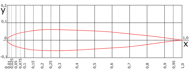
The second family of NACA airfoils was the “five-digit” series, such as the NACA 23012 airfoil. This is similar to the four-digit series but it is added with a new digit prior to the four digits. Here, the first digit gives information about the design lift coefficient. The design lift coefficient is the lift coefficient which is determined by considering only the camber of the airfoil. The design lift coefficient is used to compare the different airfoils with its capacity of generating the lift force on it. The remaining four digits are the same as mentioned in the four-digit series. For example NACA 23012 airfoil, the design lift coefficient is 0.3 i.e.,
Design lift coefficient= first digit* (3/20)
= 2*(3/20)= 0.3 (for NACA23012)


