Modified on
GT–Power Simulation for Computational Fluid Dynamics (CFD)

Skill-Lync
GT-Power is an engine simulator used by all major engine manufactures and vehicle OEMs, especially famous for a detailed cylinder model and combustion analysis. This simulator is used by a Control System Engineer for ECU development, calibration, and testing.
Since GT-Power is a method that uses 1D simulations, it offers many benefits to the field of Computational Fluid Dynamics (CFD). Let's find out how.
Need for 1D Simulation in CFD
Organization across industry rely on the 1D simulation approach as it eases the modeling where there is an interaction of different components within the system. Through 1D simulation, CFD engineers can understand the results at the early stage of the product development cycle.
1D simulations demonstrate the entire design as well as the interactions of the different components inside the system. This way, you can optimize the design of the whole system. Another major factor that favours 1D simulation is that it is not time-consuming as compared to other simulations.
Overview of GT-Suite Applications
GT-Suite is a multi-purpose platform with different libraries and countless numbers of higher-level components.
GT-Suite is used in the marine industry, railway industry, EVs, aerospace sector, and industrial machinery to design better equipment.
GT has developed specialized tools and libraries for some specific systems that include:
- Fluid System
- Fuel Economy
- Thermal Management
- Multi-Body Mechanics
- Hydraulics and Pneumatics
- Propulsion System
- Integrated System
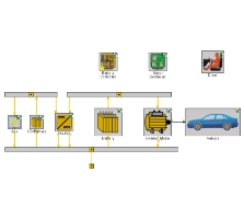
In GT, all the domains and subdomains can be integrated to form a complete model. For instance, in the case of the vehicle model, the propulsion system (engine modeling) is integrated with the fluid system (friction study) and thermal management in GT-Suite to give a steady design.
Governing Equations Used in GT-Power
The significant equations that govern the GT-Power are Continuity Equation (Conservation of mass), Momentum Equation, and Energy Equations.
Continuity Equation:
This equation signifies the law of conservation of mass. It states that the mass of fluid is conserved. Initially, the mass will change according to time, but after a certain point, the mass flow rate becomes constant.


Where m is the mass and m is the mass flow rate.
Momentum Equation:
It is based on Newton's second law, which states that the rate of change of momentum of a fluid particle equals the sum of the forces on the particle.

Where p denotes pressure on the surface, xx indicates various stress components in j direction on a surface normal to I direction, u is the velocity vector in the x-direction, SMx is the source term that accounts for body forces.
Note: The above equation is given for x-direction. Similarly, the equation can be written for y and z-direction.
Energy Equation:
The law of energy conservation states that the energy can neither be destroyed nor be created. It can only be transformed from one form to another,

Where E is the local energy density, i.e., density per unit volume, q is the energy flux.
Application of GT-Power
- Engine Performance Analysis based on 1D Fluid Dynamics
- Pressure Wave Analysis possible
- Turbocharger Matching (VGT, Wastegate)
- Detail Combustion Modeling
- After Treatment Systems
- Acoustics
- EVAP Modeling and Integrated Simulation possible
- Ability to utilize the strength of other simulation software
- 1D-3D coupling possible
- 1D-1D (GT-Power-Simulink)- Co-Simulation
GT-Power Tool - an overview
GT-Power Layout: Version 7.5
The basic layout of the GT-Suite comprises of the Project Map and library folder.
The library folder includes classified templates based on the application that is grouped under this section. For example, the Control Flow Application opens templates associated with that application.
Other libraries present besides templates include the Project Library, which consists of components used for simulation, and the Object Library, which contains Maps and inlet gas.
There is also a mini-map present on the screen along with the Project Map to make navigation easy. After finishing the whole structure, the libraries and template boxes can be minimized or closed to view the Project Map on a broader scale.
Sl 4Cyl: Sample Engine Model
The sample engine model of the Sl 4Cyl shows that the atmospheric air comes from the end environment. The flow area before the air cleaner is called the Dust Side Duct, and the flow area after the air cleaner is called the Clear Side Duct.
Along with the throttle valves present in the Sl 4Cycl model, you can also find the intake manifold (Air-cooled) and intake ports (liquid cold available on cylinder head). The injector GDI is mounted to the engine where two intake and exhaust valves are located adjacent to each other.
The side branch resonators and Helmholtz resonators are used for pressure wave tuning and NVH (Noise, vibration, and Harshness) reduction.
At the end of the model, exhaust port and exhaust manifold are associated similar to the intake port and intake manifold. The exhaust ports are connected to the 3way catalyst (used in Sl model), which can conduct a reductional oxidation reaction where HCCO is converted to H2O and CO2.
3D to 1D Gem-3D
The 3D CAD model achieved through CAD (.stl file) is discretized using GEM-3D to receive a discretized 3D model as the output. The discretization is done according to the requirement of the user.
The finer the discretization, the higher the accuracy and simulation time. After the discretization, the 3D model can be exported to the GT-Suite environment.
- PipeRound-1: The object can specify all the flow pipes with a circular cross-section and an optional bend. A special provision that the data uses to determine the bend is used to calculate pressure-Tsloss coefficients and the head losses.
- FlowSplit Genre-1: It describes the flow connected to one or more flow components. In this model, this object illustrates the inlet and outlet of an intercooler.
GT-Plot: Overview
Valve Inputs and Coefficient of Discharge
Inflow through pipes or multiple flows, throttle valve, and other input valves are used for which the coefficients of discharge are an essential factor.
Discharge coefficients across valves (orifice, throttle, EGR valve) are derived from the test data using the following equation:
Cd = Effective Area/ Reference Area
Change of area causes the pressure drop, which impacts the wave dynamics. Wave dynamics are very important for performance and acoustics calculations.

GT-Post Layout: Version 7.5
The project map is prepared with the required experimental layout and boundary conditions. After setting the model up, the simulation is run for a particular map. The results can then be opened in the GT-Post layout.
In the post layout, you can map each component to results, which are displayed at the bottom of the layout with corresponding graphs.
On the same layout, four tabs are located in the left extreme named as Plot, Case, Transient, Table. The plot tab gives an instantaneous result, while the case tab is used for steady-state. The transient tab provides the output based on the time, and the table tab summarizes the project.
Conclusion
GT-Power makes the simulation process more efficient in computational fluid dynamics (CFD). It is the best simulation tool used by leading manufactures and vehicle OEMs.
To understand the basics of GT-Power and GT-Suite, sign up for our industry-relevant course at Skill-Lync.
Check out the List of Job opportunities for your Engineering domain
Author

Akhil VausdevH
Author
Skill-Lync
Subscribe to Our Free Newsletter

Continue Reading
Related Blogs
Explore the fundamentals of vehicle dynamics and ultimate trends in the field from design and modeling to control with Skill Lync's exclusive course on the subject. Read about how Skill-Lync's CAE courses can help you get employed.
28 Jul 2020
In this article, we will briefly discuss the working, applications, and features of the one-dimensional systematic simulation tool, GT-Power, in Emission Control Strategy, engine calibration, hybrid vehicle modeling. Read about how Skill-Lync's CAE courses can help you get employed.
28 Jul 2020
This article offers a brief introduction to the globally accepted standard of Geometric Dimensioning and Tolerancing, and its importance for the entire manufacturing process. Read about how Skill-Lync's CAE courses can help you get employed.
28 Jul 2020
In this blog we will read about Going a step into Biomechanics and how Skill-Lync's CAE course will help you get employed.
09 May 2020
The powertrain is the most prominent source of vibrations that affects the driving experience for the people on board. This blog from Skill-Lync examines these vibrations to help enhance that experience.
21 Aug 2020
Author
Skill-Lync
Subscribe to Our Free Newsletter
Continue Reading
Related Blogs
Explore the fundamentals of vehicle dynamics and ultimate trends in the field from design and modeling to control with Skill Lync's exclusive course on the subject. Read about how Skill-Lync's CAE courses can help you get employed.
28 Jul 2020
In this article, we will briefly discuss the working, applications, and features of the one-dimensional systematic simulation tool, GT-Power, in Emission Control Strategy, engine calibration, hybrid vehicle modeling. Read about how Skill-Lync's CAE courses can help you get employed.
28 Jul 2020
This article offers a brief introduction to the globally accepted standard of Geometric Dimensioning and Tolerancing, and its importance for the entire manufacturing process. Read about how Skill-Lync's CAE courses can help you get employed.
28 Jul 2020
In this blog we will read about Going a step into Biomechanics and how Skill-Lync's CAE course will help you get employed.
09 May 2020
The powertrain is the most prominent source of vibrations that affects the driving experience for the people on board. This blog from Skill-Lync examines these vibrations to help enhance that experience.
21 Aug 2020
Related Courses