Co-ordinate vs Position Tolerance
Learn the key differences between Coordinate Tolerance and Position Tolerance, and how applying Position Tolerance in Geometric Dimensioning and Tolerancing (GD&T) can improve accuracy and functionality. Discover how True Position and datum-based measurements ensure repeatability, save time, and reduce costs in precision engineering.

Are you thinking that Basic Dimension (coordinate tolerance) is sufficient to determine the position ? If we apply position tolerance what are the changes ? Let's find out.
Consider a square block with four holes as shown in the figure below.
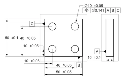
Let's consider the basic dimension.
We can form a square tolerance zone of length 0.1 and breath of 0.1.
Part will be approved only if the center of holes lie within the square tolerance zone. If the part measurement is outside the square tolerance zone either the part is rejected or submit a deviation to the designer to see if this functionally acceptable.The part created out of tolerance will cost time and money.
First step is to determine the function of the part and what is the goal when locating these holes? Assume that the part is fixed with a bolt to a slot with the dimension. We want to make sure that the center of hole is not too far from the target. Bolts are round and the holes are round. Why should the tolerance zone be limited to squares?
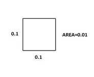
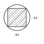
If we use position tolerance with diameter symbol we will get 56% larger tolerance zone by providing the same function
Repeatable measurement using coordinate tolerance.
To find out the center of the hole we can use CMM (Coordinate Measuring Machine) for accurate measurement. We would need to touch off the left surface and measure the hole to determine the center of the part.Then we will repeat the procedure for the y dimension from the bottom. Next, we will repeat this for all four holes to see whether the center location matches the tolerance.
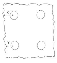
We can see that the left edge is imperfect. This will lead to a wide range of measurements that will not truly reflect how the part functions. By this method we will not get repeatable measurements that mimics the function.
Repeatable measurement using position tolerance ?
Position allows you to pinpoint a functional location for your hole center in space using datum. Then specify a tolerance around that true position.
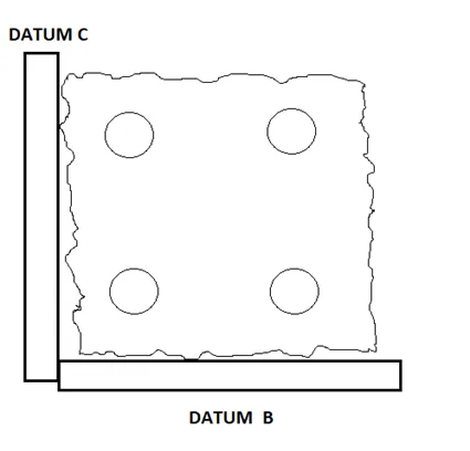
We Will use a datum feature simulator to simulate part datums and control the part with functional intent.
One of the strengths of GD&T is creating repeatable measurements that mimics the function of the part. By applying the position tolerance we save time and money. Now we can ensure that the bolts will always assemble and function on the part.
In conclusion, understanding the distinctions between Coordinate Tolerance and Position Tolerance is essential for Precision Engineering and effective Tolerance Design. While Coordinate Tolerance relies on basic dimensions to determine hole positions, Position Tolerance and True Position allow for a more functional and larger tolerance zone, enhancing the accuracy and repeatability of part measurements. Leveraging GD&T Basics, especially in Geometric Dimensioning, ensures that Engineering Tolerances, Dimensional Tolerances, and Manufacturing Tolerances align with engineering standards like ASME Y14.5. This approach to Tolerance Analysis not only improves cost-efficiency but also guarantees that parts meet stringent tolerance requirements, essential for Mechanical Engineering and Tolerance Engineering applications.


