Understanding Maximum Material Condition (MMC) and Modifiers in AutoCAD
Learn about Maximum Material Condition (MMC) and key modifiers in AutoCAD for mechanical engineers. This guide explores GD&T essentials like MMC, LMC, and projected tolerance zones, crucial for precise AutoCAD 2D and 3D CAD designs, ensuring accurate assembly and functionality.

Welcome back to the AutoCAD Essentials for Mechanical Engineers series! In this blog, we delve into the concept of Maximum Material Condition (MMC), an essential GD&T modifier used in AutoCAD for mechanical engineers to ensure precise control over the dimensions of features. Understanding MMC, along with other critical modifiers, is essential for maintaining proper fit and function in mechanical assemblies, making it a valuable concept in AutoCAD 2D and 3D environments.
What is Maximum Material Condition (MMC)?
Represented by the symbol M, MMC denotes a feature's maximum material state, where it contains the greatest amount of material within the permitted size limits. For instance:
- For an internal feature (like a hole), MMC represents the smallest allowable size.
- For an external feature (like a shaft), it’s the largest permissible size.
Applying MMC ensures minimal material removal, retaining strength and durability in a component. This concept is essential in AutoCAD mechanical engineering where high accuracy is crucial for parts subject to tight assembly requirements.
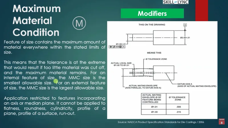
Example of MMC
Consider a data reference in AutoCAD 3D where a feature has an external tolerance of 2.01 mm. If the feature’s dimension is 1.0 to 1.01 mm, and we apply MMC, this tolerance zone ensures the feature doesn’t exceed 0.15 mm. The CAD programs allow engineers to control this through various tolerance settings, enabling the design of precise assemblies that hold up under stress.
Least Material Condition (LMC)
In contrast to MMC, the Least Material Condition (LMC) is used when minimum material retention is essential. This setting ensures that the component maintains a minimal level of material, thus facilitating assembly while avoiding excess material removal.
LMC guarantees that even with the minimal amount of material, parts can fit and function as intended. This condition is critical for applications where parts must fit snugly, as LMC prevents excessive material removal that would affect the functionality. When applied, LMC ensures that enough material remains for proper assembly, particularly beneficial in mechanical AutoCAD 2D drawings.
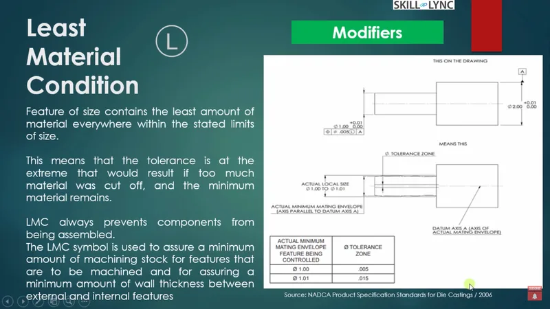
Additional Modifiers: Expanding Control in AutoCAD
In AutoCAD 2024, several additional modifiers add flexibility to tolerancing, allowing engineers to adapt GD&T settings based on specific assembly requirements. These modifiers include the projected tolerance zone, unequal tolerance zone, and tangent plane.
Projected Tolerance Zone (P)
This modifier is beneficial in cad programs when designing mating parts. Represented by P, it allows the tolerance zone to project onto an adjacent feature, useful for aligning two interacting components such as a bolt and hole. Engineers can use this modifier to define universal tolerance zones across mating components, simplifying stack-up analysis in assemblies.
Unequal Tolerance Zone (U)
In instances where a feature needs varying tolerance across its profile, U offers an unequal tolerance zone. This modifier allows engineers to adjust tolerance zones asymmetrically, providing control over one end of a profile independently from the other. AutoCAD tutorials cover this modifier in-depth, as it is essential for parts with asymmetrical design requirements.
Tangent Plane (T)
The tangent plane modifier (T) simplifies tolerance applications by only requiring high points on a surface to fall within the tolerance zone. This approach reduces the complexity of traditional tolerance methods, which require every point on a surface to meet tolerance requirements.
- Rules of GD&T: Essential Guidelines for Precision
GD&T in AutoCAD for beginners introduces two foundational rules that govern the application of modifiers, each vital for ensuring accurate manufacturing and inspection.
Rule 1: Perfect Form at MMC
This rule states that if only a tolerance size is specified, the feature must maintain a perfect form at MMC. For instance, a 50 mm diameter part with a ±0.01 mm tolerance must maintain exact dimensions within 50.1 mm under MMC. It ensures the feature remains precise, avoiding undulations or other errors.
Rule 2: Regardless of Feature Size (RFS)
RFS is the default condition when no specific modifier is applied, ensuring tolerance application independent of feature size. This rule is vital for functions where size variation is minimal but consistent. RFS is commonly applied to concentricity and symmetry controls, ensuring precise alignment without introducing additional tolerance zones.
Feature Control Frame: Structuring GD&T in AutoCAD
The feature control frame in AutoCAD drawing consolidates all GD&T symbols and modifiers, organizing them into compartments that clarify tolerance specifications for each feature. The frame is segmented as follows:
- Geometric Characteristic Symbol: Indicates tolerance type (e.g., form, orientation).
- Tolerance Zone Description: Details tolerance range for each feature.
- Modifier Symbols: Lists applicable modifiers such as MMC, LMC, or U for unequal tolerance zones.
- Datum References: If needed, additional references can be added to specify data planes.
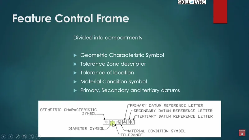
Applying GD&T in AutoCAD
Adding GD&T annotations in AutoCAD mechanical drawings is straightforward, allowing you to apply specific tolerances directly to features. Here’s a step-by-step process:
- Create the Feature: Start by drawing a basic shape, such as a rectangle or shaft cross-section.
- Invoke the Tolerance Command (D): This command opens the GD&T dialog box, where you can specify required tolerances.
- Define Tolerance Values: Set tolerance values like 0.001 mm for straightness or apply projected tolerance zones to mating parts.
- Apply Modifiers: Use the modifier dropdown to select MMC, LMC, or tangent plane options based on your requirements.
For example, applying a tolerance of 0.001 mm with MMC to a shaft’s straightness ensures minimal deviation, providing control over the shaft’s alignment.
Practical Example: Feature Control Frame in Action
Consider an AutoCAD mechanical drawing of a cross-section shaft. Using the tolerance command, add a GD&T frame specifying 0.01 mm parallelism relative to a datum plane. This setup ensures precise parallel alignment across the shaft’s length. AutoCAD 3D crash courses often emphasize this process, as it’s essential for achieving accuracy in complex assemblies.
Conclusion
Understanding Maximum Material Condition and other modifiers in AutoCAD online environments empowers engineers to create robust and precise designs. Whether using the best AutoCAD course or learning through a CAD tutorial, mastering GD&T in AutoCAD 2D and 3D settings ensures that your designs meet the highest standards of accuracy and reliability.
With these GD&T tools, mechanical engineers can ensure that components are consistently manufactured to precise tolerances, achieving the quality and performance required in modern mechanical engineering.
This blog is part of our ongoing AutoCAD Design Series. If you missed the previous posts, check them out here.
Would you like to have a more interactive experience going through the AutoCAD essentials?
Skill-Lync has released a FREE comprehensive course covering AutoCAD Essentials for Mechanical Engineers in detail! Check it out here.
If you’re looking to go deeper into AutoCAD Essentials check out Skill-Lync’s AutoCAD certification course.
Check out our hands-on course today and add AutoCAD to your list of skills!
Let’s get #IndustryReady together, one skill at a time!


