Understanding Datum Reference Frames and Tolerancing in AutoCAD
Explore the role of datum reference frames and tolerancing in AutoCAD for mechanical engineering. This guide covers assembly fits, allowances, and clearance essentials to ensure precision and compatibility in CAD design.

Welcome to AutoCAD Essentials for Mechanical Engineers series. Today we’re diving into the practical application of datum reference frames, essential for precision in engineering drawings. Understanding datum reference frames is crucial in AutoCAD for engineers, as these frames provide reliable references for measurement and alignment, ultimately ensuring the consistency of parts during assembly and inspection.
What Are Datum Reference Frames?
Datum reference frames are composed of three mutually perpendicular intersecting planes, providing a 3D framework, often referred to as XYZ planes. These reference frames, visualized in AutoCAD 2D and 3D, guide users in denoting primary, secondary, and tertiary planes for precise component placement and measurement. Within mechanical AutoCAD 2D drawing or AutoCAD 3D modeling, the primary datum plane typically has three contact points, the secondary has two, and the tertiary has one—each chosen based on the geometry and needs of the component.

Using Datum Features and Simulators
In practical applications, datum features—surfaces, axes, or edges on a part—are assigned to align the component in the datum reference frame. To simulate how an actual part aligns with these references, CAD software like AutoCAD mechanical uses a datum feature simulator, an imaginary boundary or surface used for reference. These simulators are critical when setting manufacturing tolerances to ensure components meet design requirements and can be reproduced reliably across production.
A useful tool in inspection and quality control is the go/no-go gauge. It allows engineers to assess if a component’s dimensions meet or exceed set limits, providing a straightforward acceptance or rejection based on tolerance adherence. For example, when measuring an external surface in AutoCAD mechanical drawing to fit within defined tolerances, you would use a datum feature simulator aligned to the reference datum axis, ensuring compliance with your specifications.
Tolerances in Assembly: Allowance and Clearance
In AutoCAD, setting the right tolerances is vital for successful component assembly. Two essential terms in this process are allowance and clearance:
Allowance is the intentional difference allowed between two components, ensuring maximum material limits are maintained when they fit together.
Clearance refers to the smallest space between two assembled parts, essential for parts requiring movement or adjustment.
Applying Fits in AutoCAD for Mechanical Engineering
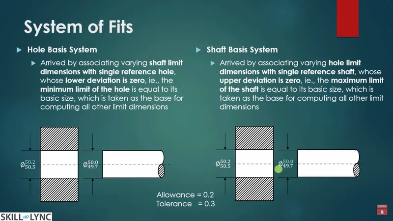
In AutoCAD for mechanical engineers, fits—especially clearance, transition, and interference fits—help define the tolerance type and ensure proper component function. When using CAD software to design assembly parts, two systems commonly guide fitment: the hole-basis system and the shaft-basis system.
- Hole-Basis System: Here, the hole size is kept constant while the shaft size varies. For instance, a 50 mm diameter hole with a tolerance range from 50.2 mm to 50.5 mm can accommodate shafts with minimum and maximum limits of 49.7 mm and 50 mm, respectively.
- Shaft-Basis System: This system keeps the shaft size constant while adjusting the hole. A shaft size of 50 mm may allow for a hole size that ranges from 50.2 mm to 50.5 mm, ensuring an ideal fit depending on the required tolerance.
Understanding Fit Types for Assembly
AutoCAD mechanical engineering applications often require three fit types:
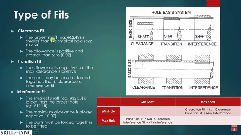
- Clearance Fit: Allows parts to slide or rotate freely. For example, a shaft diameter of 12.48 mm and a hole diameter of 12.5 mm provide a 0.02 mm clearance.
- Interference Fit: Ensures parts stay locked together. Special processes like heating or cooling may be needed to assemble parts, as seen in automotive assemblies.
- Transition Fit: Bridges the gap between clearance and interference, with one part fitting snugly but not tightly within another.
Representing Fits in AutoCAD
AutoCAD lets you assign letters and numbers to represent fit types (e.g., H7 for holes, f8 for shafts). These notations, based on the whole-basis or shaft-basis system, denote tolerance and deviation limits, crucial for understanding the relationship between mating parts.
Conclusion
Understanding datum reference frames, tolerances, allowances, and fit types are essential for AutoCAD mechanical engineering applications. These concepts form the foundation for producing reliable, interchangeable parts in CAD design. Whether you’re creating an AutoCAD 2D drawing for beginners or tackling advanced 3D CAD assemblies, mastering these fundamentals is key for any engineer aiming to ensure quality and precision in their designs.
This blog serves as part of the AutoCAD Essentials series, providing a comprehensive foundation in design software for mechanical engineers.
This blog is part of our ongoing AutoCAD Design Series. If you missed the previous posts, check them out here.
Would you like to have a more interactive experience going through the AutoCAD essentials?
Skill-Lync has released a FREE comprehensive course covering AutoCAD Essentials for Mechanical Engineers in detail! Check it out here.
If you’re looking to go deeper into AutoCAD Essentials check out Skill-Lync’s AutoCAD certification course.
Check out our hands-on course today and add AutoCAD to your list of skills!
Let’s get #IndustryReady together, one skill at a time!


